Bayesian optimization of electron energy from laser wakefield accelerator
Abstract
We employ Bayesian optimization combined with three-dimensional particle-in-cell simulations to identify the optimal laser and plasma parameters that, for a given laser pulse energy, maximize the cut-off energy of an electron beam accelerated via laser wakefield acceleration. A Gaussian laser driver with a matched spot size and amplitude is assumed, interacting with both a uniform-density plasma and a preformed plasma channel of matched radius. To interpret the simulation results quantitatively, we derive novel analytical expressions for predicting the maximum electron energy and acceleration length, taking into account the diffraction and energy depletion of the laser pulse. Additionally, we discuss the potential scalability of the optimal parameters for high-energy lasers.
I Introduction
Laser wakefield acceleration (LWFA) is a rapidly evolving technique, which stands out for its ability to achieve acceleration gradients several orders of magnitude higher than conventional accelerators [1, 2, 3]. This method relies on the interaction between an intense laser pulse and plasma, where the laser drives a plasma wave that can trap and accelerate electrons to relativistic energies. Over the past few decades, LWFA has gained significant attention for its potential to produce compact electron accelerators with a wide range of applications, from advanced radiation sources [4, 5, 6, 7, 8] to exploring strong-field quantum electrodynamics phenomena [9, 10].
In LWFA, proper settings of initial laser and plasma parameters are crucial for optimizing various characteristics of accelerated electron beams. Such optimization, however, presents an imposing challenge due to the highly nonlinear and multi-parametric nature of the problem. Furthermore, it is often desired to optimize multiple, potentially conflicting objectives simultaneously, hence requiring to identify an appropriate trade-off.
Although the dependence of certain electron beam properties on input parameters can be described by analytical formulae, these all rely on a number of simplifying assumptions (e.g., a non-evolving laser pulse). In practice, the effects of a self-consistent evolution of laser and plasma significantly limit the applicability of these models and alternative methods might be needed. Numerical simulations are often employed to account for the complex interactions between the laser and plasma, yet simulations with sufficient spatial and temporal resolution to adequately capture the involved physics are computationally very expensive. On the other hand, the range of parameters that can be explored through experimental methods is intrinsically limited by the capabilities of existing laser systems.
In this work, we aim to identify the optimal set of laser and plasma parameters that, for a given laser pulse energy, maximize the cut-off energy (i.e., the energy threshold beyond which there are very few or no particles) of an electron beam accelerated via LWFA. At this stage, we focus on optimizing the cut-off energy alone, without regard to other electron beam parameters. This is motivated by the needs of specific applications, where achieving a high cut-off energy is essential, while other beam characteristics are of secondary importance (e.g., muon production [11, 12] and nuclear activation [13, 14]).
To reduce the number of free parameters, we make the following assumptions: (i) LWFA is driven by a linearly polarized Gaussian laser pulse with a constant spectral phase; (ii) the plasma has uniform density profile along the laser propagation direction; and (iii) LWFA is operated in the matched regime [15]. It is important to note that, under these assumptions, the maximum possible electron energy is not necessarily achieved (see, e.g., LWFA using non-Gaussian [16, 17] or chirped [18, 19] laser pulses, tailored plasma targets [20, 21], or strongly mismatched regime [22, 23]). More advanced settings, however, introduce additional parameters, further complicating the optimization process. We anticipate the consideration of such cases in future work.
To achieve our goal, we use Bayesian optimization (BO), where the objective function (i.e., the observable to be optimized – in our case, the electron cut-off energy) is sampled using three-dimensional (3D) particle-in-cell (PIC) simulations. Our task thus involves optimizing an expensive-to-evaluate, derivative-free, and potentially non-convex function. For such problems, BO is particularly suited. BO, including its modifications (e.g., multi-objective and multi-fidelity BO), has already been successfully applied for addressing complex tasks in LWFA [24, 25, 26, 27, 28, 29, 30].
We demonstrate our approach using a laser pulse with relatively low energy (), as in this case, the optimal acceleration distance is reasonably long (less than in all the simulated cases). This makes the set of PIC simulations required for the convergence of BO computationally feasible. We optimize two scenarios, LWFA with and without a preformed plasma channel of matched radius, to investigate its impact on the electron energy. To interpret the simulation results quantitatively, we derive novel analytical expressions for predicting the maximum electron energy and the corresponding acceleration length, taking into account the diffraction and energy depletion of the laser pulse. Additionally, we express the optimization results using dimensionless parameters and discuss their potential scalability.
The remainder of this paper is organized as follows: In Sec. II, we revisit the fundamental theory of relativistically strong laser pulse propagation in tenuous plasma; in Sec. III, we introduce novel analytical expressions for the maximum LWFA electron energy and acceleration length; Secs. IV and V contain the setup of the BO algorithm and the PIC simulations, respectively; in Sec. VI, we present the optimization results for the cases of a uniform-density plasma (Sec. VI.1) and a preformed plasma channel of matched radius (Sec. VI.2); we discuss the potential scalability of the optimal parameters in Sec. VII; and finally, we summarize our findings in Sec. VIII.
II Propagation of intense laser pulse in plasma
The profile of a Gaussian laser pulse can be characterized by its vector potential; being normalized by , where is the electron mass, is the velocity of light in vacuum, and is the elementary charge, the vector potential is
| (1) |
Here, a scalar description of a Gaussian pulse (i.e., ignoring polarization) is used.
For a radially symmetric profile, the amplitude, , and phase, , depend on the longitudinal coordinate, , radial coordinate, , time, , and the coordinate co-moving with the laser pulse at the group velocity as
| (2) |
and
| (3) |
respectively. Here, , , and denote the angular frequency, wavenumber, and the finite length of the laser pulse, respectively, where is the full-width-at-half-maximum (FWHM) duration measured in the intensity profile. The laser amplitude, , and width, , are defined as
| (4) |
and
| (5) |
where is the strength parameter of the laser pulse and is the laser waist, i.e., the radius at which the intensity drops to of its peak value at the focus. The Rayleigh length, , is defined as the distance from the focus along the propagation direction to the point where the laser radius increases by a factor of compared to the waist.
Further, we consider that the laser central wavelength, , and energy,
| (6) |
are given. Here, , , and is the classical electron radius. The laser power is then
| (7) |
Upon propagating in a fully ionized plasma, a relativistically strong laser pulse (i.e., ) can either be guided by some form of external optical guiding or self-guided. Whether the pulse is self-guided or not depends on the relationship between its power and the critical power for relativistic self-focusing [31],
| (8) |
where is the electron number density and
| (9) |
is the critical plasma density. When , the laser pulse is not self-guided, meaning it diffracts as it propagates in plasma. Diffraction reduces the laser amplitude, preventing the electrons from being efficiently accelerated over a sufficiently long distance. On the other hand, when , nonlinear effects (e.g., laser filamentation instability [32, 33], formation of solitons [34, 35] and vortices [36]) may arise which can distort the laser pulse profile and hinder the acceleration process. Therefore, maintaining an appropriate balance between the laser power and the critical power for relativistic self-focusing is crucial to ensure effective electron acceleration in plasma. We express the ratio of to as a function of and ,
| (10) | ||||
For self-guided propagation of a laser pulse in plasma without significant changes to the pulse profile over multiple Rayleigh lengths, the laser strength parameter and waist should be set according to the matching conditions [15]. Here, we rewrite the matching conditions using and as
| (11) | ||||
and
| (12) | ||||
with being the plasma frequency. Therefore, under the considerations specified above, the question of maximizing the LWFA electron energy reduces to searching for a combination of only two parameters, and (or, equivalently, ).
We suppose that the optimal value of should not be far from the optimal pulse duration for the wakefield excitation, i.e., which maximizes the difference between the extremal values of the wakefield potential left behind the pulse. We estimate by numerically solving the following differential equation, which assumes one-dimensional quasi-static approximation and uniform-density plasma with stationary ions [2],
| (13) | ||||
Here, is the wakefield potential normalized by , is the phase velocity of the plasma wave, is the corresponding Lorentz factor of the plasma wave, and is the plasma wavenumber.
III electron acceleration
The maximum energy that can be imparted to an electron through LWFA is determined by the strength of the accelerating field and the length over which the acceleration occurs, both of which depend on multiple interrelated factors. In addition to the diffraction of unguided laser pulses mentioned in Sec. II, the electron energy may be constrained by the dephasing length (i.e., the distance over which the electron outruns the accelerating phase of the wakefield) or by laser energy depletion, which is accompanied by modifications to the pulse shape.
In the course of energy depletion, the laser pulse transfers its energy to the kinetic energy of plasma electrons, part of which is subsequently transferred to the plasma wave. The energy depletion length, , can thus be estimated by equating the laser energy, Eq. (6), with the total energy gained by electrons during the interaction over a propagation distance equal to . Considering that an electron located at acquires, on average, an energy of [37], the energy depletion length can be expressed as
| (14) |
where and correspond to a uniform-density plasma and a parabolic plasma channel with radius , respectively. If the pulse length is comparable to the optimal length for wakefield generation, , the energy depletion length is proportional to .
To account for the effects of laser guiding and energy depletion in plasma, we modify the functions and given by Eqs. (4) and (5), respectively, as [2]
| (15) |
and
| (16) |
Eq. (16) predicts “catastrophic” focusing for ; this is, however, mitigated by higher-order effects [38, 39].
For the laser pulse approaching the threshold of relativistic self-focusing, the longitudinal electric field left behind the pulse in plasma can be calculated within the framework of linear approximation [2, 40]. In the units of , the electric field reads as
| (17) |
where is the initial phase of the plasma wave. The net change of the kinetic energy of the ultra-relativistic electron, i.e., , accelerated by the electric field given by Eq. (17) along the longitudinal coordinate can be (in the units of ) calculated as
| (18) |
For the unguided laser pulse (i.e., ) the effect of laser diffraction is typically much more detrimental than the energy depletion. Neglecting the energy depletion length () and calculating the integral in Eq. (18), we obtain
| (19) | ||||
Expression (19) has maximum for and ,
| (20) |
Considering a laser pulse with spot size given by Eq. (12), the Rayleigh length is equal to . Using further the approximation for (i.e., a low-density plasma limit), the formula for the maximum electron energy in the case of unguided laser pulse takes the following simple form,
| (21) |
The acceleration length, which is predominantly constrained by the laser diffraction, is thus
| (22) |
For the guided laser pulse (i.e., ), the diffraction is eliminated and the main mechanism limiting the maximum electron energy is the laser energy depletion. Calculating the integral in Eq. (18) for the guided pulse, we get
| (23) | ||||
Expression (LABEL:eq:ene_guided) has maximum for and . Assuming further and , the formula for the maximum electron energy in the case of guided laser pulse takes the following simple form,
| (24) |
The acceleration length, which is predominantly constrained by the laser energy depletion, is thus
| (25) |
In the case of a pulse length near the optimal length for wakefield generation, is proportional to .
IV Bayesian optimization
The key components of the BO method are the probabilistic surrogate model of the objective function, which fits the observed data points while quantifying uncertainty in unobserved regions, and the acquisition function, which determines the next point to evaluate. We employ a Gaussian process (GP) [41] as the surrogate model and the upper confidence bound (UCB) [42] as the acquisition function.
A critical aspect of BO is balancing exploration (i.e., searching the broader parameter space) and exploitation (i.e., probing areas near the current known optimum). The UCB acquisition function includes a free parameter that allows us to control this balance. We set this parameter to be decaying, i.e., it initially prioritizes exploration to allow a thorough search of the parameter space, and gradually shifts towards exploitation as more points are evaluated. This strategy minimizes the risk of getting trapped in local extrema and increases the likelihood of finding the global optimum.
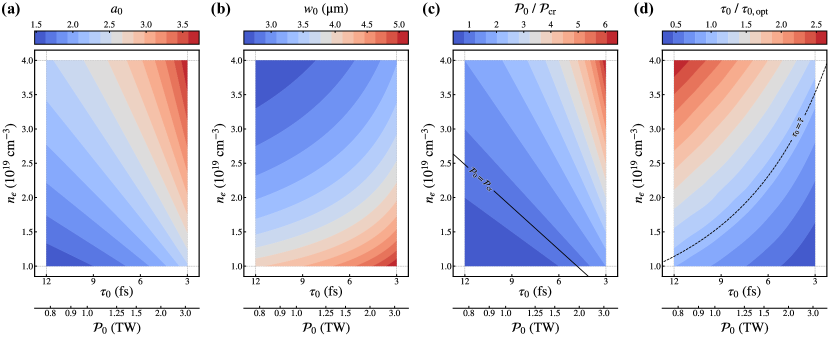
Based on the reasoning presented in Sec. II, we initiate the search for the optimal case near the intersection of the contour curves and . For a laser with and , these curves intersect at and , and the matching conditions (11) and (12) yield and , respectively. We restrict the parameter space for the BO algorithm to and . If these bounds prove inadequate, they can be dynamically adjusted during the optimization process. Within the selected parameter range, the optimal pulse duration for the wakefield excitation depends on the electron density approximately as follows,
| (26) |
Panels (a)–(c) of Fig. 1 show , , and given by Eqs. (11), (12), and (10), respectively, and panel (d) shows calculated numerically using Eq. (13) at a uniform grid and interpolated with cubic splines. All the variables are displayed within the prescribed limits of and considering and . The contours of and can be seen in panels (c) and (d), respectively.
V Particle-in-cell simulations
We perform two sets of PIC simulations in the 3D Cartesian geometry using the EPOCH code [43]. The laser and plasma parameters used in the simulations are listed in Tabs. 1 and 2 for the cases of a laser propagation in a uniform-density plasma and a preformed plasma channel of matched radius, respectively. The first four simulations in both cases, – and – , are selected based on our educated guess, while the following simulations are determined iteratively by the BO algorithm.
A linearly polarized laser pulse propagates in a fully ionized plasma slab. We add a short smooth ramp to the front side of the slab in order to suppress the artificial plasma wave breaking (and thus the electron injection into the plasma wave) at the sharp plasma-vacuum interface. In the case of a preformed plasma channel, the electron density profile has an additional parabolic dependence on the radial coordinate [44],
| (27) |
Here, is the matched radius of the channel, which can be calculated as [44]
| (28) |
The focal spot of the laser pulse is located at from the entrance to the plasma.
A sufficient amount of electron charge is introduced into the plasma wave (while avoiding excessive beam loading [45] that distorts the accelerating field) using the method of nanoparticle-assisted injection [46]. A lithium nanoparticle with a radius of is placed on the laser propagation axis, from the entrance to the plasma. At this point, the wakefield structure is already fully developed, but the laser pulse has not yet lost any significant portion of its energy. Additionally, this method ensures that the electron injection occurs at the same location in each simulation, regardless of whether self-injection [47] is present or not, allowing for a fair comparison of electron energies between individual simulation cases. We employ the nanoparticle-assisted injection for the sake of its relative simplicity; provided that the electrons are injected at the same location, the cut-off energy does not depend on the choice of injection mechanism.
The simulations utilize the moving window technique. The simulation window, having the longitudinal and transverse dimensions of and , respectively, moves along the laser propagation direction at a velocity equal to . The underlying Cartesian grid is uniform with the resolution of cells per in each direction. The simulations are evolved over a time interval sufficient to capture the electron dephasing length.
The plasma is cold and collisionless. The electrons are represented by quasi-particles with triangular shape functions, whereas the ions form a static neutralizing background. Initially, there is one electron quasi-particle in each grid cell. The equations of motion for quasi-particles are solved using the Boris algorithm [48], the electric and magnetic fields are calculated using the standard second-order Yee solver [49]. Absorbing boundary conditions are applied on each of the simulation domain sides for both the fields and quasi-particles.
VI Optimization results
VI.1 Uniform-density plasma
First, we present the optimization results in the case of a uniform-density plasma. The GP model for the cut-off energy of the electron beam, , and the corresponding acceleration distance, , based on the results of 18 PIC simulation (parameters are listed in Tab. 1) are shown in panels (a) and (b) of Fig. 2, respectively. The cut-off energy is defined as the upper limit of the energy distribution with spectral density of at least , and the acceleration length as the distance from injection to the point where the electrons reach their maximum cut-off energy. We do not distinguish whether the acceleration length is determined by laser diffraction, energy depletion, electron dephasing, or other effects.
The maximum cut-off energy of the electron beam estimated by the BO algorithm is and this energy is acquired over the acceleration distance . This optimal case is characterized by the following set of laser and plasma parameters: , , , and . As can be seen, even in a relatively narrow parameter space, the cut-off energies and acceleration lengths vary significantly ( from to and from to ), highlighting the importance of the proper choice of the initial laser and plasma parameters. While the maximum cut-off energies are concentrated in a clearly identified region, the acceleration lengths grow predominantly with the decrease of electron density.
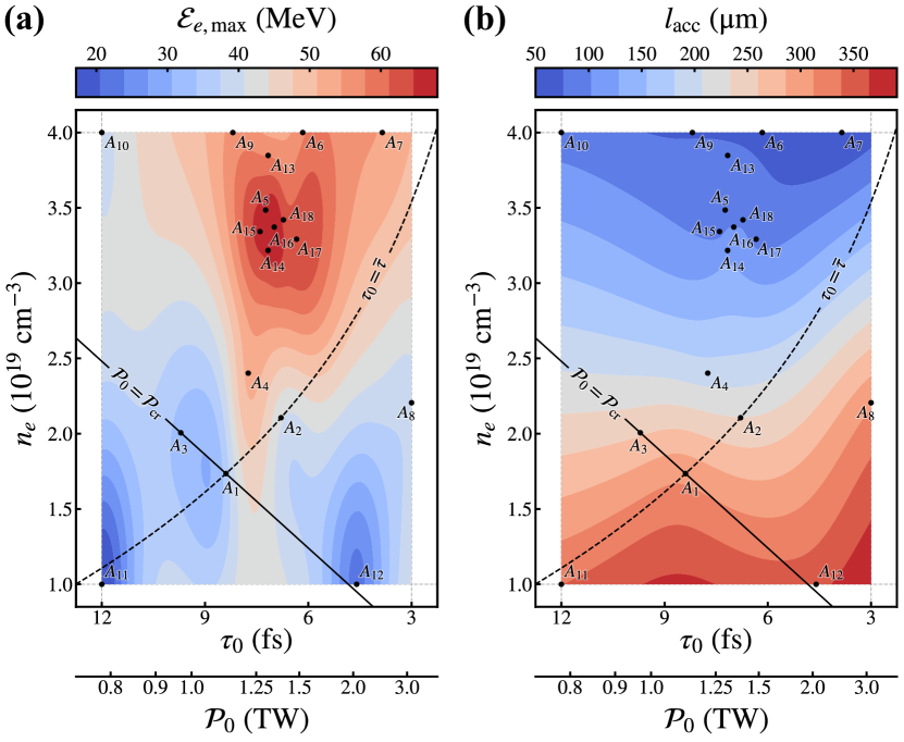

As discussed in Sec. II, in a uniform-density plasma, the laser pulse can be regarded as guided as long as the condition is satisfied. However, for a more precise description, the evolution of the laser during its interaction with the plasma must be considered, as this leads to laser energy depletion and the consequent loss of laser power. This power loss is partially compensated by plasma wave-induced compression of the laser pulse [50, 51], and the self-guiding is prolonged. Nevertheless, once the power drops below the critical threshold for relativistic self-focusing, the laser pulse diffracts rapidly and the electron acceleration ceases. This explains why, in panel (a) of Fig. 2, the region of maximum cut-off energies is located slightly above the contour curves and .
The maximum electron energy according to Eq. (24) for the optimal parameters found by BO is . The corresponding acceleration distance determined by Eq. (25) is . Both values are in good agreement with the simulation results. The slightly lower value of predicted by Eq. (24) may arise from the use of a linear approximation when calculating the accelerating field, while the slightly longer according to Eq. (25) may reflect the depletion of a small portion of laser energy before electron injection takes place.
Panels (a) and (b) of Fig. 3 display, respectively, the spatial and spectral characteristics of the output electron beam obtained from – the PIC simulation with parameters closest to the optimum found by BO in a uniform-density plasma (parameters are listed in Tab. 1). As can be seen, the energy spectrum is relatively broad since it involves the electrons injected into several periods of the plasma wave not only via the nanoparticle-assisted injection but also through the self-injection that occurs later during the interaction. The total charge of electrons with energy above is and their angular distribution reveals a FWHM divergence of . We point out that these characteristics were not the subject of optimization.
VI.2 Preformed plasma channel of matched radius
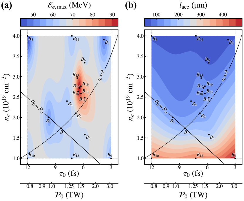
Second, we present the optimization results in the case of a preformed plasma channel of matched radius. The GP model for and based on the results of 18 PIC simulation (parameters are listed in Tab. 2) are shown in panels (a) and (b) of Fig. 4, respectively. The maximum cut-off energy of the electron beam estimated by the BO algorithm is now and this energy is acquired over the acceleration distance . This optimal case is characterized by the following set of laser and plasma parameters: , , , , and .
As shown in panel (a) of Fig. 4, the highest electron cut-off energies are concentrated within a narrow region of the parameter space. Outside this region, the cut-off energy distribution becomes more uniform and approaches the maximum achievable in a uniform-density plasma. This illustrates the effect of a preformed plasma channel with a matched radius, which suppresses laser diffraction and enables electron acceleration until the laser energy is significantly depleted or electron dephasing occurs. Relaxing the guiding conditions allows LWFA operation even when , where the quality of the electron beam may improve, albeit at the cost of requiring a longer acceleration distance. As shown in panel (b) of Fig. 4, the acceleration distances again grow with decreasing electron density.
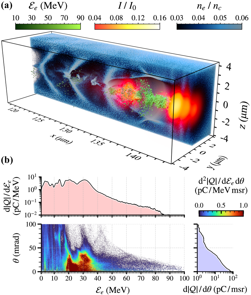
Panels (a) and (b) of Fig. 5 show, respectively, the spatial and spectral characteristics of the output electron beam obtained from – the PIC simulation with parameters closest to the optimum found by BO in a preformed plasma channel (parameters are listed in Tab. 2). The total charge of electrons with energy above is now almost ten times higher compared to the optimal case in a uniform-density plasma, . The angular distribution of electron beam shows a FWHM divergence of . Again, no efforts were made to optimize these characteristics.
For the optimal parameters, the maximum electron energy according to Eq. (24) is and the corresponding acceleration distance according to Eq. (25) is . The discrepancy between the theory and the simulation results can be attributed to the mechanism described in Ref. 52. At later stages of the interaction, there is a significant overlap between the accelerated electrons and the red-shifted field of the laser pulse [see Fig. 5(a)], which may lead to the onset of direct laser acceleration [53]. This additional mechanism could enhance the ultimate energy gain of the accelerated electrons, complementing the primary process of LWFA.
VII Discussion
The optimization of LWFA driven by relatively low-energy laser pulses (as in this work) is of particular interest for present-day high-repetition-rate laser systems [54, 55]. The scalability of the optimal parameters may be influenced by various factors, such as carrier-envelope phase effects for very short pulses [56, 57], ion motion for very long pulses [58, 59], or single-particle effects due to the distance between individual electrons in very low-density plasma. Verifying the optimized scaling for high-energy lasers through simulation requires advanced techniques (e.g., field decomposition into azimuthal Fourier modes [60] and Lorentz-boosted frame [61]), to address the increased computational load associated with long acceleration distances. We plan to pursue such verification in future work.
As shown in Sec. II, LWFA operated in the matched regime can be described using only two parameters; these can be further expressed in a dimensionless form as and . In a uniform-density plasma, we have for the optimal case found in this work and . Disregarding the effects mentioned in previous paragraph and rescaling the optimal parameters to, e.g., laser pulse, they translate to , , , and . Note that the optimal value of remains constant, regardless of the laser pulse energy. For such hypothetical LWFA setup, Eqs. (24) and (25) give for the maximum electron energy and the corresponding acceleration length, respectively, and .
VIII Conclusion
By leveraging the BO method and 3D PIC simulations, we efficiently find the LWFA regime that maximizes the cut-off energy of an electron beam while minimizing the number of simulations required. We show that with laser pulse and appropriately chosen laser and plasma parameters, one can produce electron beams with cut-off energy almost in a uniform-density plasma and more than using a preformed plasma channel of matched radius.
To interpret the results of simulations quantitatively, we derive novel analytical expressions for predicting the maximum electron energy and the corresponding acceleration length, taking into account the effects of laser pulse diffraction and energy depletion. Additionally, we express the optimization results in terms of dimensionless parameters, which may contribute to the development of optimized electron energy scaling of LWFA driven by high-energy lasers.
IX Acknowledgements
We acknowledge fruitful discussions with G. M. Grittani, M. Jech, M. Kando, K. G. Miller, A. S. Pirozhkov, B. A. Reagan, B. Rus, B. K. Russel, and P. V. Sasorov.
This work was supported by the Defense Advanced Research Program Agency (DARPA) under the Muons for Science and Security Program and by the NSF and Czech Science Foundation (NSF-GACR collaborative Grant No. 2206059 and Czech Science Foundation Grant No. 22-42963L). This work was supported by the project “e-INFRA CZ” (ID:90254) from the Ministry of Education, Youth and Sports of the Czech Republic. A portion of this work was performed under the auspices of the U.S. Department of Energy by Lawrence Livermore National Laboratory (LLNL) under Contract DE-AC52-07NA27344 and supported by the LLNL Institutional Computing Grand Challenge program. The EPOCH code used in this work was in part funded by the UK EPSRC grants EP/G054950/1, EP/G056803/1, EP/G055165/1, EP/M022463/1, and EP/P02212X/1. We acknowledge the use of the following software package: “Bayesian Optimization: Open source constrained global optimization tool for Python” [62].
*
Appendix A Simulation parameters and results
Tabs. 1 and 2 contain the parameters of the PIC simulations as well as the corresponding cut-off electron energy and acceleration length for the cases of uniform-density plasma and a preformed plasma channel of matched radius, respectively.
| 8.39 | 3.61 | 2.00 | 32.6 | 299 | ||
| 6.79 | 3.50 | 2.29 | 39.7 | 241 | ||
| 9.71 | 3.35 | 2.00 | 33.9 | 249 | ||
| 7.75 | 3.28 | 2.29 | 50.8 | 188 | ||
| 7.24 | 2.93 | 2.65 | 66.2 | 102 | ||
| 6.16 | 2.87 | 2.93 | 57.2 | 65 | ||
| 3.85 | 3.11 | 3.43 | 54.2 | 52 | ||
| 3.00 | 3.95 | 3.05 | 39.3 | 308 | ||
| 8.19 | 2.74 | 2.66 | 55.6 | 74 | ||
| 12.00 | 2.57 | 2.35 | 40.1 | 89 | ||
| 12.00 | 4.08 | 1.48 | 17.2 | 338 | ||
| 4.60 | 4.79 | 2.04 | 22.8 | 357 | ||
| 7.17 | 2.84 | 2.75 | 57.6 | 82 | ||
| 7.17 | 3.01 | 2.59 | 66.0 | 120 | ||
| 7.40 | 2.96 | 2.60 | 66.0 | 98 | ||
| 6.99 | 2.98 | 2.65 | 67.9 | 102 | ||
| 6.34 | 3.05 | 2.72 | 63.9 | 97 | ||
| 6.72 | 2.99 | 2.70 | 63.9 | 100 |
| 8.39 | 3.61 | 2.00 | 2.94 | 60.4 | 168 | ||
| 6.79 | 3.50 | 2.29 | 3.05 | 67.3 | 145 | ||
| 9.71 | 3.35 | 2.00 | 2.73 | 55.3 | 146 | ||
| 7.75 | 3.28 | 2.29 | 2.86 | 61.4 | 113 | ||
| 5.82 | 3.96 | 2.19 | 3.37 | 64.8 | 208 | ||
| 5.84 | 3.08 | 2.81 | 2.97 | 66.5 | 73 | ||
| 3.77 | 3.14 | 3.42 | 3.35 | 51.0 | 66 | ||
| 12.00 | 2.57 | 2.35 | 2.27 | 43.7 | 69 | ||
| 3.00 | 5.15 | 2.35 | 4.54 | 57.8 | 487 | ||
| 12.00 | 4.08 | 1.48 | 2.86 | 62.5 | 397 | ||
| 7.22 | 2.80 | 2.78 | 2.69 | 60.6 | 59 | ||
| 7.24 | 4.44 | 1.75 | 3.38 | 62.9 | 402 | ||
| 6.25 | 3.32 | 2.52 | 3.03 | 87.0 | 126 | ||
| 5.83 | 3.40 | 2.55 | 3.13 | 80.3 | 140 | ||
| 6.65 | 3.14 | 2.59 | 2.90 | 80.6 | 109 | ||
| 6.25 | 3.24 | 2.58 | 3.00 | 88.3 | 115 | ||
| 6.39 | 3.25 | 2.55 | 2.99 | 92.8 | 122 | ||
| 6.56 | 3.27 | 2.50 | 2.98 | 88.9 | 118 |
References
- Tajima and Dawson [1979] T. Tajima and J. M. Dawson, Physical Review Letters 43, 267 (1979).
- Esarey et al. [2009] E. Esarey, C. B. Schroeder, and W. P. Leemans, Reviews of Modern Physics 81, 1229 (2009).
- Gonsalves et al. [2019] A. J. Gonsalves, K. Nakamura, J. Daniels, C. Benedetti, C. Pieronek, T. C. H. de Raadt, S. Steinke, J. H. Bin, S. S. Bulanov, J. van Tilborg, C. G. R. Geddes, C. B. Schroeder, Cs. Tóth, E. Esarey, K. Swanson, L. Fan-Chiang, G. Bagdasarov, N. Bobrova, V. Gasilov, G. Korn, P. Sasorov, and W. P. Leemans, Physical Review Letters 122, 084801 (2019).
- Grüner et al. [2007] F. Grüner, S. Becker, U. Schramm, T. Eichner, M. Fuchs, R. Weingartner, D. Habs, J. Meyer-ter-Vehn, M. Geissler, M. Ferrario, L. Serafini, B. van der Geer, H. Backe, W. Lauth, and S. Reiche, Applied Physics B 86, 431 (2007).
- Corde et al. [2013] S. Corde, K. Ta Phuoc, G. Lambert, R. Fitour, V. Malka, A. Rousse, A. Beck, and E. Lefebvre, Reviews of Modern Physics 85, 1 (2013).
- Bulanov et al. [2013] S. V. Bulanov, T. Z. Esirkepov, M. Kando, A. S. Pirozhkov, and N. N. Rosanov, Physics-Uspekhi 56, 429 (2013).
- Albert et al. [2014] F. Albert, A. G. R. Thomas, S. P. D. Mangles, S. Banerjee, S. Corde, A. Flacco, M. Litos, D. Neely, J. Vieira, Z. Najmudin, R. Bingham, C. Joshi, and T. Katsouleas, Plasma Physics and Controlled Fusion 56, 084015 (2014).
- Kurz et al. [2021] T. Kurz, T. Heinemann, M. F. Gilljohann, Y. Y. Chang, J. P. Couperus Cabadağ, A. Debus, O. Kononenko, R. Pausch, S. Schöbel, R. W. Assmann, M. Bussmann, H. Ding, J. Götzfried, A. Köhler, G. Raj, S. Schindler, K. Steiniger, O. Zarini, S. Corde, A. Döpp, B. Hidding, S. Karsch, U. Schramm, A. Martinez de la Ossa, and A. Irman, Nature Communications 12, 2895 (2021).
- Gonoskov et al. [2022] A. Gonoskov, T. G. Blackburn, M. Marklund, and S. S. Bulanov, Reviews of Modern Physics 94, 045001 (2022).
- Yu et al. [2024] T.-P. Yu, K. Liu, J. Zhao, X.-L. Zhu, Y. Lu, Y. Cao, H. Zhang, F.-Q. Shao, and Z.-M. Sheng, Reviews of Modern Plasma Physics 8, 24 (2024).
- Terzani et al. [2024] D. Terzani, S. Kisyov, S. Greenberg, L. L. Pottier, M. Mironova, A. Picksley, J. Stackhouse, H.-E. Tsai, R. Li, E. Rockafellow, T. Heim, M. Garcia-Sciveres, C. Benedetti, J. Valentine, H. Milchberg, K. Nakamura, A. J. Gonsalves, J. van Tilborg, C. B. Schroeder, E. Esarey, and C. G. R. Geddes, Measurement of directional muon beams generated at the Berkeley Lab Laser Accelerator (2024), arXiv:2411.02321 [physics] .
- Zhang et al. [2024] F. Zhang, L. Deng, Y. Ge, J. Wen, B. Cui, K. Feng, H. Wang, C. Wu, Z. Pan, H. Liu, Z. Deng, Z. Zhang, L. Chen, D. Yan, L. Shan, Z. Yuan, C. Tian, J. Qian, J. Zhu, Y. Xu, Y. Yu, X. Zhang, L. Yang, W. Zhou, Y. Gu, W. Wang, Y. Leng, Z. Sun, and R. Li, First Proof of Principle Experiment for Muon Production with Ultrashort High Intensity Laser (2024), arXiv:2410.23829 [physics] .
- Nedorezov et al. [2021] V. G. Nedorezov, S. G. Rykovanov, and A. B. Savel’ev, Physics-Uspekhi 64, 1214 (2021).
- Kolenatý et al. [2022] D. Kolenatý, P. Hadjisolomou, R. Versaci, T. M. Jeong, P. Valenta, V. Olšovcová, and S. V. Bulanov, Physical Review Research 4, 023124 (2022).
- Lu et al. [2007] W. Lu, M. Tzoufras, C. Joshi, F. S. Tsung, W. B. Mori, J. Vieira, R. A. Fonseca, and L. O. Silva, Physical Review Special Topics - Accelerators and Beams 10, 61301 (2007).
- Beaurepaire et al. [2015] B. Beaurepaire, A. Vernier, M. Bocoum, F. Böhle, A. Jullien, J.-P. Rousseau, T. Lefrou, D. Douillet, G. Iaquaniello, R. Lopez-Martens, A. Lifschitz, and J. Faure, Physical Review X 5, 031012 (2015).
- Oumbarek Espinos et al. [2023] D. Oumbarek Espinos, A. Rondepierre, A. Zhidkov, N. Pathak, Z. Jin, K. Huang, N. Nakanii, I. Daito, M. Kando, and T. Hosokai, Scientific Reports 13, 18466 (2023).
- Kalmykov et al. [2012] S. Y. Kalmykov, A. Beck, X. Davoine, E. Lefebvre, and B. A. Shadwick, New Journal of Physics 14, 033025 (2012).
- Kim et al. [2017] H. T. Kim, V. B. Pathak, K. Hong Pae, A. Lifschitz, F. Sylla, J. H. Shin, C. Hojbota, S. K. Lee, J. H. Sung, H. W. Lee, E. Guillaume, C. Thaury, K. Nakajima, J. Vieira, L. O. Silva, V. Malka, and C. H. Nam, Scientific Reports 7, 10203 (2017).
- Sprangle et al. [2001] P. Sprangle, B. Hafizi, J. R. Peñano, R. F. Hubbard, A. Ting, C. I. Moore, D. F. Gordon, A. Zigler, D. Kaganovich, and T. M. Antonsen, Physical Review E 63, 056405 (2001).
- Guillaume et al. [2015] E. Guillaume, A. Döpp, C. Thaury, K. Ta Phuoc, A. Lifschitz, G. Grittani, J.-P. Goddet, A. Tafzi, S. W. Chou, L. Veisz, and V. Malka, Physical Review Letters 115, 155002 (2015).
- Perevalov et al. [2020] S. E. Perevalov, K. F. Burdonov, A. V. Kotov, D. S. Romanovskiy, A. A. Soloviev, M. V. Starodubtsev, A. A. Golovanov, V. N. Ginzburg, A. A. Kochetkov, A. P. Korobeinikova, A. A. Kuz’min, I. A. Shaikin, A. A. Shaykin, I. V. Yakovlev, E. A. Khazanov, and I. Y. Kostyukov, Plasma Physics and Controlled Fusion 62, 094004 (2020).
- Põder et al. [2024] K. Põder, J. C. Wood, N. C. Lopes, J. M. Cole, S. Alatabi, M. P. Backhouse, P. S. Foster, A. J. Hughes, C. Kamperidis, O. Kononenko, S. P. D. Mangles, C. A. J. Palmer, D. Rusby, A. Sahai, G. Sarri, D. R. Symes, J. R. Warwick, and Z. Najmudin, Physical Review Letters 132, 195001 (2024).
- Shalloo et al. [2020] R. J. Shalloo, S. J. D. Dann, J.-N. Gruse, C. I. D. Underwood, A. F. Antoine, C. Arran, M. Backhouse, C. D. Baird, M. D. Balcazar, N. Bourgeois, J. A. Cardarelli, P. Hatfield, J. Kang, K. Krushelnick, S. P. D. Mangles, C. D. Murphy, N. Lu, J. Osterhoff, K. Põder, P. P. Rajeev, C. P. Ridgers, S. Rozario, M. P. Selwood, A. J. Shahani, D. R. Symes, A. G. R. Thomas, C. Thornton, Z. Najmudin, and M. J. V. Streeter, Nature Communications 11, 6355 (2020).
- Jalas et al. [2021] S. Jalas, M. Kirchen, P. Messner, P. Winkler, L. Hübner, J. Dirkwinkel, M. Schnepp, R. Lehe, and A. R. Maier, Physical Review Letters 126, 104801 (2021).
- Kirchen et al. [2021] M. Kirchen, S. Jalas, P. Messner, P. Winkler, T. Eichner, L. Hübner, T. Hülsenbusch, L. Jeppe, T. Parikh, M. Schnepp, and A. R. Maier, Physical Review Letters 126, 174801 (2021).
- Jalas et al. [2023] S. Jalas, M. Kirchen, C. Braun, T. Eichner, J. B. Gonzalez, L. Hübner, T. Hülsenbusch, P. Messner, G. Palmer, M. Schnepp, C. Werle, P. Winkler, W. P. Leemans, and A. R. Maier, Physical Review Accelerators and Beams 26, 071302 (2023).
- Ferran Pousa et al. [2023] A. Ferran Pousa, S. Jalas, M. Kirchen, A. Martinez de la Ossa, M. Thévenet, S. Hudson, J. Larson, A. Huebl, J.-L. Vay, and R. Lehe, Physical Review Accelerators and Beams 26, 084601 (2023).
- Irshad et al. [2023] F. Irshad, S. Karsch, and A. Döpp, Physical Review Research 5, 013063 (2023).
- Irshad et al. [2024] F. Irshad, C. Eberle, F. M. Foerster, K. v. Grafenstein, F. Haberstroh, E. Travac, N. Weisse, S. Karsch, and A. Döpp, Physical Review Letters 133, 085001 (2024).
- Sun et al. [1987] G.-Z. Sun, E. Ott, Y. C. Lee, and P. Guzdar, Physics of Fluids 30, 526 (1987).
- Naumova et al. [2002] N. M. Naumova, S. V. Bulanov, K. Nishihara, T. Zh. Esirkepov, and F. Pegoraro, Physical Review E 65, 045402 (2002).
- Valenta et al. [2021] P. Valenta, G. M. Grittani, C. M. Lazzarini, O. Klimo, and S. V. Bulanov, Physics of Plasmas 28, 122104 (2021).
- Bulanov et al. [1999] S. V. Bulanov, T. Zh. Esirkepov, N. M. Naumova, F. Pegoraro, and V. A. Vshivkov, Physical Review Letters 82, 3440 (1999).
- Esirkepov et al. [2002] T. Zh. Esirkepov, K. Nishihara, S. V. Bulanov, and F. Pegoraro, Physical Review Letters 89, 275002 (2002).
- Bulanov et al. [1996] S. V. Bulanov, M. Lontano, T. Zh. Esirkepov, F. Pegoraro, and A. M. Pukhov, Physical Review Letters 76, 3562 (1996).
- Mourou et al. [2006] G. A. Mourou, T. Tajima, and S. V. Bulanov, Reviews of Modern Physics 78, 309 (2006).
- Sprangle et al. [1987] P. Sprangle, C.-M. Tang, and E. Esarey, IEEE Transactions on Plasma Science 15, 145 (1987).
- Hafizi et al. [2000] B. Hafizi, A. Ting, P. Sprangle, and R. F. Hubbard, Physical Review E 62, 4120 (2000).
- Terzani et al. [2023] D. Terzani, C. Benedetti, S. S. Bulanov, C. B. Schroeder, and E. Esarey, Physical Review Accelerators and Beams 26, 113401 (2023).
- Rasmussen and Williams [2005] C. E. Rasmussen and C. K. I. Williams, Gaussian Processes for Machine Learning (The MIT Press, 2005).
- Auer [2002] P. Auer, Journal of Machine Learning Research 3, 397 (2002).
- Arber et al. [2015] T. D. Arber, K. Bennett, C. S. Brady, A. Lawrence-Douglas, M. G. Ramsay, N. J. Sircombe, P. Gillies, R. G. Evans, H. Schmitz, A. R. Bell, and C. P. Ridgers, Plasma Physics and Controlled Fusion 57, 113001 (2015).
- Bobrova et al. [2001] N. A. Bobrova, A. A. Esaulov, J.-I. Sakai, P. V. Sasorov, D. J. Spence, A. Butler, S. M. Hooker, and S. V. Bulanov, Physical Review E 65, 016407 (2001).
- Wilks et al. [1987] S. Wilks, T. Katsouleas, J. M. Dawson, P. Chen, and J. J. Su, IEEE Transactions on Plasma Science 15, 210 (1987).
- Cho et al. [2018] M. H. Cho, V. B. Pathak, H. T. Kim, and C. H. Nam, Scientific Reports 8, 16924 (2018).
- Bulanov et al. [1998] S. Bulanov, N. Naumova, F. Pegoraro, and J. Sakai, Physical Review E 58, R5257 (1998).
- Boris [1971] J. P. Boris, in Proceedings of the Fourth Conference on Numerical Simulation of Plasmas, edited by J. P. Boris and R. A. Shanny (Naval Research Laboratory, 1971) pp. 3–67.
- Yee [1966] K. S. Yee, IEEE Transactions on Antennas and Propagation 14, 302 (1966).
- Faure et al. [2005] J. Faure, Y. Glinec, J. J. Santos, F. Ewald, J.-P. Rousseau, S. Kiselev, A. Pukhov, T. Hosokai, and V. Malka, Physical Review Letters 95, 205003 (2005).
- Schreiber et al. [2010] J. Schreiber, C. Bellei, S. P. D. Mangles, C. Kamperidis, S. Kneip, S. R. Nagel, C. A. J. Palmer, P. P. Rajeev, M. J. V. Streeter, and Z. Najmudin, Physical Review Letters 105, 235003 (2010).
- Shaw et al. [2017] J. L. Shaw, N. Lemos, L. D. Amorim, N. Vafaei-Najafabadi, K. A. Marsh, F. S. Tsung, W. B. Mori, and C. Joshi, Physical Review Letters 118, 064801 (2017).
- Pukhov et al. [1999] A. Pukhov, Z.-M. Sheng, and J. Meyer-ter-Vehn, Physics of Plasmas 6, 2847 (1999).
- Faure et al. [2019] J. Faure, D. Gustas, D. Guénot, A. Vernier, F. Böhle, M. Ouillé, S. Haessler, R. Lopez-Martens, and A. Lifschitz, Plasma Physics and Controlled Fusion 61, 14012 (2019).
- Lazzarini et al. [2024] C. M. Lazzarini, G. M. Grittani, P. Valenta, I. Zymak, R. Antipenkov, U. Chaulagain, L. V. N. Goncalves, A. Grenfell, M. Lamač, S. Lorenz, M. Nevrkla, A. Špaček, V. Šobr, W. Szuba, P. Bakule, G. Korn, and S. V. Bulanov, Physics of Plasmas 31, 030703 (2024).
- Valenta et al. [2020] P. Valenta, T. Z. Esirkepov, J. K. Koga, A. Nečas, G. M. Grittani, C. M. Lazzarini, O. Klimo, G. Korn, and S. V. Bulanov, Physical Review E 102, 53216 (2020).
- Huijts et al. [2022] J. Huijts, L. Rovige, I. A. Andriyash, A. Vernier, M. Ouillé, J. Kaur, Z. Cheng, R. Lopez-Martens, and J. Faure, Physical Review X 12, 011036 (2022).
- Farina and Bulanov [2001] D. Farina and S. V. Bulanov, Physical Review Letters 86, 5289 (2001).
- Zhou et al. [2012] S.-Y. Zhou, W. Yu, X. Yuan, H. Xu, L. H. Cao, H. B. Cai, and C. T. Zhou, Physics of Plasmas 19, 093101 (2012).
- Lifschitz et al. [2009] A. F. Lifschitz, X. Davoine, E. Lefebvre, J. Faure, C. Rechatin, and V. Malka, Journal of Computational Physics 228, 1803 (2009).
- Vay [2007] J.-L. Vay, Physical Review Letters 98, 130405 (2007).
- Nogueira [2014] F. Nogueira, Bayesian Optimization: Open source constrained global optimization tool for Python (2014).