Nonreciprocal ballistic transport in multi-layer Weyl Semimetal films
with surface engineering
Abstract
Weyl semimetal (WSM) thin films possess unique electronic properties that differ from bulk materials. In this article, we study the nonreciprocal ballistic transport of the WSM thin films caused by surface modification. We find that the surface states contribute predominantly to the nonreciprocity, while the bulk states provide a negative correction. Our calculation shows a kind of quantum size effect that the nonreciprocal signal decreases as the WSM film becomes thicker, and diverges when the Fermi energy is near the bottom of a sub-band. On the other hand, it is found that the density of states in multi-layer systems possesses some properties roughly independent of thickness. A single-variable theory is developed to explain it.
I Introduction
Nonreciprocity in charge transport reflects an asymmetrical relationship between current and voltage, where the magnitude of current changes when the voltage has an opposite sign [1, 2]. Although nonreciprocal transport is commonly observed in systems breaking the translational symmetry, for example the p-n junction, the achievement of nonreciprocity in translationally symmetric systems has emerged more recently. After extensive exploration to identify material candidates, there have been significant findings such as chiral nanosystems [3, 4], polar semiconductors [5, 6, 7], bilayer heterojunctions [8, 9, 10, 11, 12], and topological systems. On the theoretical side, a variety of mechanisms have been proposed to explain the new phenomena, including asymmetric band structures [1, 5], asymmetric inelastic scattering by spin clusters [13] and magnons [14], quantum metric [15, 16], quantum interferences[17], and the non-Hermitian skin effect [18, 19]. In this article, we concentrate on the nonreciprocal transport in systems characterized by asymmetric bands.
Compared to bulk materials which most previous theories focus on, the study of nonreciprocity in thin-film materials seems more valuable. On the one hand, thin films are more commonly used in experimental measurements [5], some of which can already be fabricated to be quite thin [20, 21, 22]. On the other hand, the more pronounced quantum effects and surface effects allow thin films to possess different properties from their bulk samples. The WSM thin film is a good example, which is a superior choice for the study of interfacial charge transfer effect, spin Hall effect, spin-charge pumping, spin-orbit torque effect, and finally thickness dependent magnetotransport measurements [20]. Besides, compared to bulk samples, WSM thin films possess unique properties, such as anisotropic weak antilocalization [21], larger coercive fields, pronounced hysteresis in the magnetoresistance and highly tunable anomalous Hall conductivity [22]. Recently, nonreciprocity induced by surface engineering has been predicted in WSM bulk systems [23]. In order to meet the needs of actual experimental measurements, a theory of nonreciprocity in thin-film materials is necessary.
WSMs are three-dimensional topological quantum materials characterized by an even number of points in momentum space known as Weyl nodes (WNs) [24, 25]. At certain surfaces of a WSM, topologically protected surface states known as Fermi arcs connect a couple of WNs of opposite chiralities. Normally, either time-reversal symmetry (TRS) or spatial inversion symmetry (SIS) is maintained in the WSM, ensuring a symmetric band structure. However, recent advancements in research suggest that Fermi arcs can be manipulated through surface modifications, making asymmetric band structures possible for WSMs [26, 27, 28, 29, 30], which would hopefully lead to nonreciprocity. In this case, it is the surface states (Fermi arcs) rather than the bulk states that dominate the nonreciprocity, which is rare in traditional materials. Compared to bulk WSMs, such surface engineering is supposed to have a more pronounced impact to the films due to the greater surface effects. Therefore, larger nonreciprocity is assumed to be achieved in WSM thin films.
In this article, we calculate the nonreciprocity in the system of multi-layer WSM films. Considering the significant quantum effects, the semiclassical Boltzmann transport theory is no longer applicable. So we use the gauge-invariant theory in the ballistic regime [31]. Besides easier fabrication and larger nonreciprocal signal in experiment, thin films make it possible to study how the surface states and bulk states contribute differently to nonreciprocity. Furthermore, we also study how thickness of the sample affects the nonreciprocity. Through the change of thickness, some rough thickness-independent properties of the density of states (DOS) is observed, which may be common in multi-layer systems.
The rest of the article is organized as follows. In Sec. II, the model Hamiltonian as well as the gauge-invariant theory for nonreciprocal ballistic transport is introduced. In Sec. III, the numerical results are presented and the behavior of the nonreciprocal signal is discussed. Finally, in Sec. IV, we present our concluding remarks.
II Model and Method
II.1 Model Hamiltonian of the two-node WSM film with surface manipulation
Consider the following Hamiltonian of a two-node WSM on a simple cubic lattice as
| (1) |
where is the electron momentum; are the Pauli matrices; and denote model parameters. The lattice constant is set as .
TRS is broken in this model while SIS is maintained, so that there exit two Weyl nodes. The energy spectrum is
| (2) |
The two WNs are located separately at with energy . In this system, the SIS is maintained and TRS is broken,
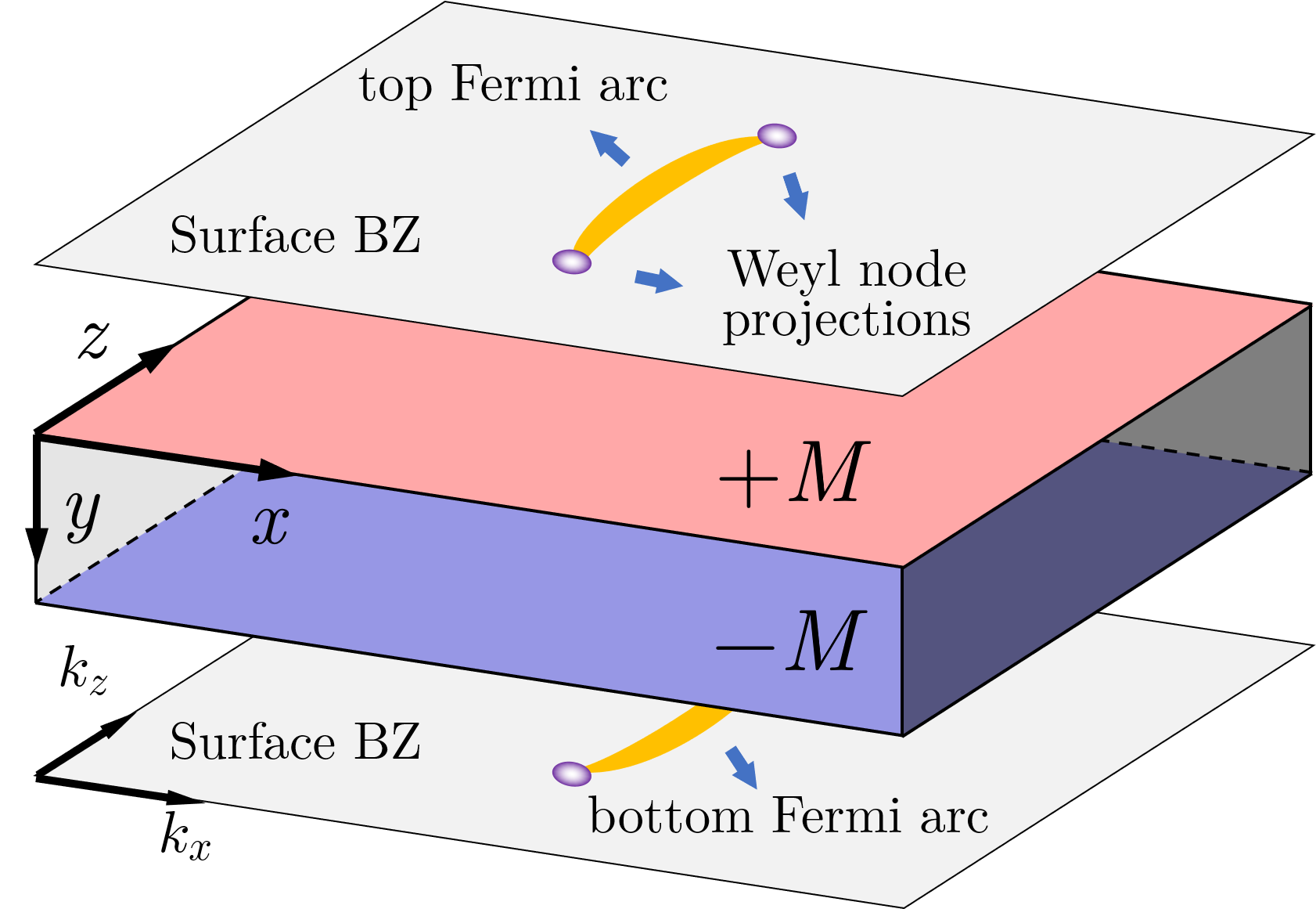
By confining the system in the direction, we obtain a WSM film with nontrivial upper and lower surfaces, as is shown in Fig. 1. Both surfaces hold projections of the WNs connected by Fermi arcs. Supposing the WSM has layers in the direction, the Hamiltonian can be expressed as
| (3) |
with
| (4) |
where denotes the onsite terms and denotes the hopping terms in the direction; is the momentum component; is the layer index.
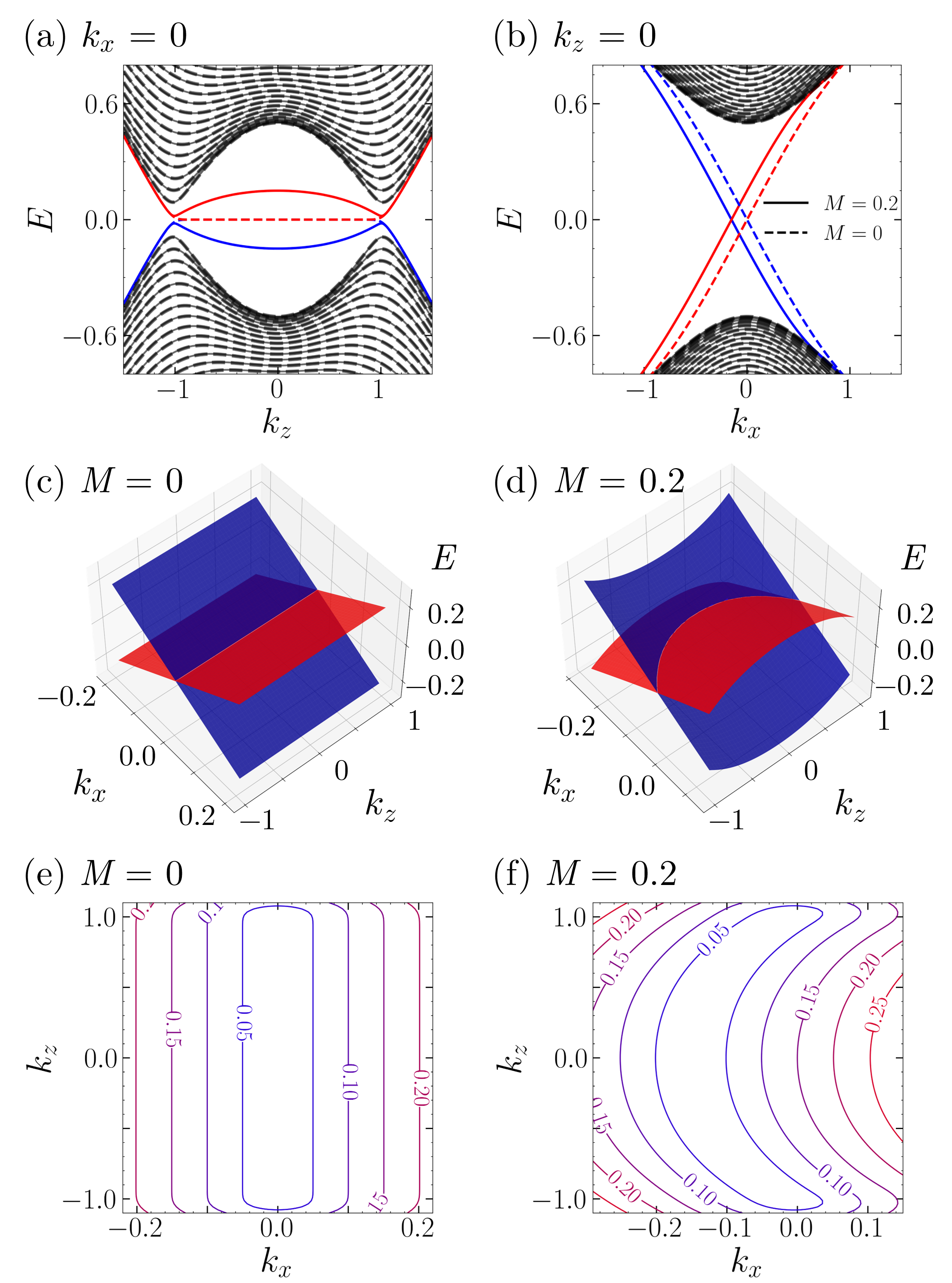
The energy spectrum of such a WSM film is shown in Figs. 2(a) and (b) with dashed lines. The bulk states are shown in black. In Fig. 2(a) we can see two Weyl valleys along with the energy gap, which gradually closes when becomes larger. When is not too small, we can roughly find the two WNs like the bulk cases. For example, the two WNs are at approximately in Fig. 2(a) with . The two chiral surface states are shown in red and blue, which cross the energy gap in an opposite way, linking the upper and lower energy bands, as is shown in Fig. 2(b).
Unlike the 3D bulk model characterized by Eq. (1), both SIS and TRS are satisfied in the multi-layer model with . Utilizing the qsymm package [32], we identify the unitary operator related to SIS as , where is the unit antidiagonal square matrix with order ,
| (5) |
The operator transform the Hamiltonian as
| (6) |
Since the mirror symmetry along the direction is always maintained, the mirror symmetry along the direction is equivalent to SIS, so we will not mention it specially in the rest. TRS is represented by the antiunitary operator as , where is the complex conjugation operator. It satisfies
| (7) |
which is similar to as happens to be real. Besides, the system also satisfies the chiral symmetry (CS), represented by the unitary operator as which satisfies
| (8) |
As is shown in Fig. 2, both SIS and TRS guarantee the symmetric band structure along the direction, while CS guarantees the energy spectrum symmetric about . In order to obtain asymmetric bands, SIS and TRS have to be broken; but for convenience we want CS to be maintained. So antisymmetric potentials are introduced respectively to the upper () and lower () surfaces, as is shown in Fig. 1. The Hamiltonian becomes
| (9) |
The corresponding energy spectrum is shown in Figs. 2(a) and (b) with solid lines. Although the bulk states barely change, the surface states experience severe deformation because of the surface modification. To make it more clear, we display the 3D and contour plots of the surface states spectrum respectively in Figs. 2(c-f). It shows that nonzero breaks the symmetry along the direction (Figs. 2(d) and (f)) compared to the case (Figs. 2(c) and (e)), giving rise to nonreciprocity, as we will show in the following section.
II.2 Gauge-invariant theory for nonreciprocal ballistic transport
Consider quantum coherent transport taking place in mesoscopic system with connection to multiple terminals labeled by . The electric current in terminal driven by the bias voltages is expressed as [33, 34, 35, 36]
| (10) |
where is the Fermi-Dirac distribution function in terminal , with , the equilibrium Fermi energy, and the bias voltage. The transmission from terminal to is given by , where is the retarded (advanced) Green’s function defined as
| (11) |
with the retarded (advanced) self-energy introduced by terminal that satisfy . The linewidth function is defined as . For a two-terminal setup, the unitarity of the scattering matrix [37] ensures .
In Eq. (11), is the Hamiltonian of the system in equilibrium, i.e., all bias voltages vanish (). The additional term is the Coulomb potential arising from a finite bias, which satisfies the Poisson equation [38]
| (12) |
where denotes the position. The potential plays an essential role for the nonreciprocal ballistic transport as the asymmetric band structures are considered. The lesser Green’s function is defined as , with
| (13) |
In general, a self-consistent approach is required to solve Eqs. (11)-(13) in the nonlinear regime. Since the lesser Green’s function exhibits a nonlinear relationship with , Eq. (12) is a nonlinear differential equation. Nevertheless, the entire theoretical framework is gauge-invariant [38], which means that the current is invariant under a uniform potential shift applied throughout the system.
Here, we focus on the weakly nonlinear regime, where the Coulomb potential can be expanded as
| (14) |
where the zeroth-order term (potential in equilibrium) has been absorbed into the Hamiltonian , and denotes the characteristic potential [33, 38]. Gauge invariance of the theory requires [33]
| (15) |
To the lowest order, we derive the equation for from Eqs. (12) and (14) [39, 33] as
| (16) |
where is the local charge density, and the injectivity or local partial density of states (LPDOS) of terminal [39, 33] is given by
| (17) |
in which is the equilibrium Green’s function with . An alternative expression for injectivity in terms of scattering wavefunctions and the velocity of incident modes is [40, 41]
| (18) |
where is the zero-bias distribution function, and are the wave function and velocity corresponding to the incident mode from terminal . The total injectivity contains the contributions from all terms as
| (19) |
In the weakly nonlinear regime, we expand the current to the second-order of the bias voltages as [33, 38, 42]
| (20) |
For a uniform system, the spatial distribution of the eigenstates is independent of , and so is the LPDOS . Similarly, the Coulomb potential remains constant throughout the scattering region so that the characteristic potentials satisfy . The characteristic potentials are then expressed as
| (21) |
This result is consistent with the local neutral approximation [33, 40, 38], where the local charge density is assumed to be zero everywhere inside the system. In the weak nonlinear regime we yield
| (22) |
where , and the first-order and second-order conductances are expressed as
| (23) |
In the limit of zero temperature, the integration in Eq. (22) simplifies to
| (24) |
where the energy is assumed to be at the Fermi energy .
III Result and Discussion
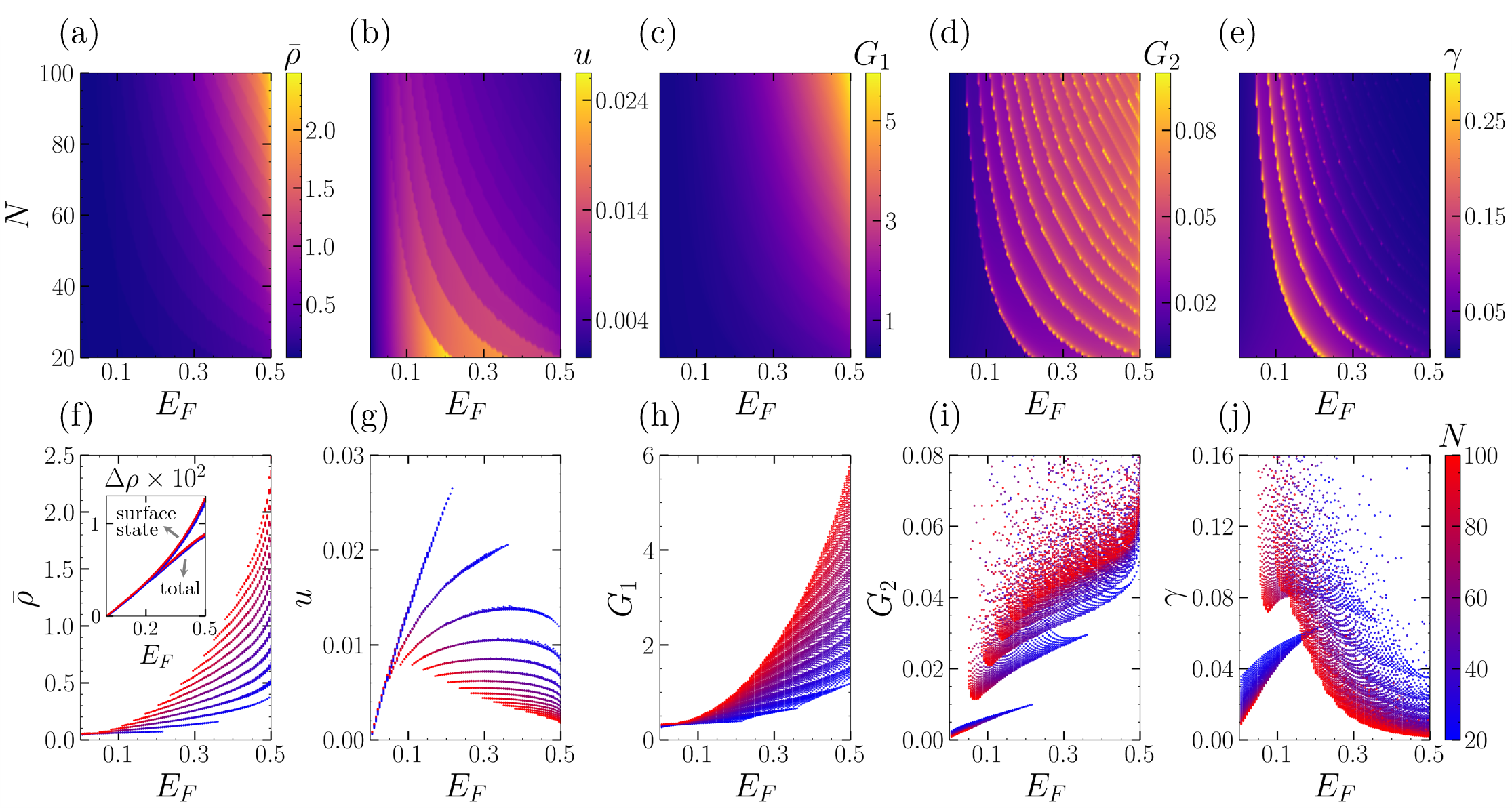
In the first row of Fig. 3, we present contour plots of various physical quantities as functions of the Fermi energy and the number of layers . From left to right, these are DOS , the electric potential , the first-order conductance , the second-order conductance , and which is defined as to characterizes the relative strength of non-reciprocity. We can see identical series of boundary lines in these plots, indicating that these physical quantities undergo transitions at similar locations. These boundary lines are curves composed of Van Hove singularities, corresponding to the distribution of sub-band bottom energies. As the Fermi energy (number of layers) increases, with each boundary line passed, an additional sub-band is counted in. The region with the lowest energy corresponds to the surface state, and the rest are bulk bands.
Taking the contour plot of the density of states in Fig. 3(a) as an example. There are fewer sub-regions in the lower left part of the graph because the sub-bands are sparse in the low-energy region and only a few sub-bands contribute to the DOS. The upper right part of the graph has more sub-regions, and the sub-bands are dense, with more sub-bands contributing to the DOS in the high-energy region. Therefore, Fig. 3(a) shows a trend that the density of states increases as we move towards the upper right. In the insert, we show the difference in DOS of left and right, denoted as . The lower curve represents the total difference of DOS, while the upper shows the difference from the surface states only. According to Eqs. (21) and (23), the surface states make a predominant contribution to the electric potential as well as the second-order conductance . The bulk states only contribute some negative corrections.
Figs. 3(c) and (d), which represent the first-order and second-order conductances, exhibit a similar situation. The more bands are involved in transport, the greater the conductances are. However, in Eq. (23) leads to divergence of the second-order conductance at the bottom of the sub-bands, from which we can observe highlighted boundary lines. The quantity in Fig. 3(e) is complicated. Firstly, the competition between the first-order and second-order conductances leads to an initial increase and subsequent decrease in as more sub-bands participate in transport. This results in its maximum value appearing at several low-energy bulk states. Additionally, also diverges at the bottom of the sub-bands. This implies that in experiments, there may be a significant non-reciprocal signal near the bottom of the low-energy bands. As to Fig. 3(b), we will discuss it in detail in the following section as the behavior of the electric potential is very interesting.
In the second row of Fig. 3, we present the aforementioned physical quantities in another way. They are scatter plots of the corresponding physical quantities from Figs. 3(a-e) as functions of the Fermi energy, with different colors representing different numbers of layers. These scatter plots more clearly demonstrate the cluster phenomenon caused by sub-bands. In particular, peculiar behavior of DOS the electric potential are shown that in contrast to the blocky clusters in the other three plots, their clusters form a series of curves. Let’s first explain how the DOS scatter plot in Fig. 3(f) forms curves. In Fig. 4(a), the curves of the DOS are shown as a function of the Fermi energy for several given numbers of layers. It can be seen that they rise in a stepwise manner. On the step surfaces, the DOS changes continuously; when the Fermi energy encounters the bottom of a sub-band, the DOS undergoes a jump, entering a higher step. This echoes our previous explanation, where the boundaries of the steps correspond to the bottom energies of certain sub-bands. It can be seen that these step surfaces, coming from different , collectively form these curves.
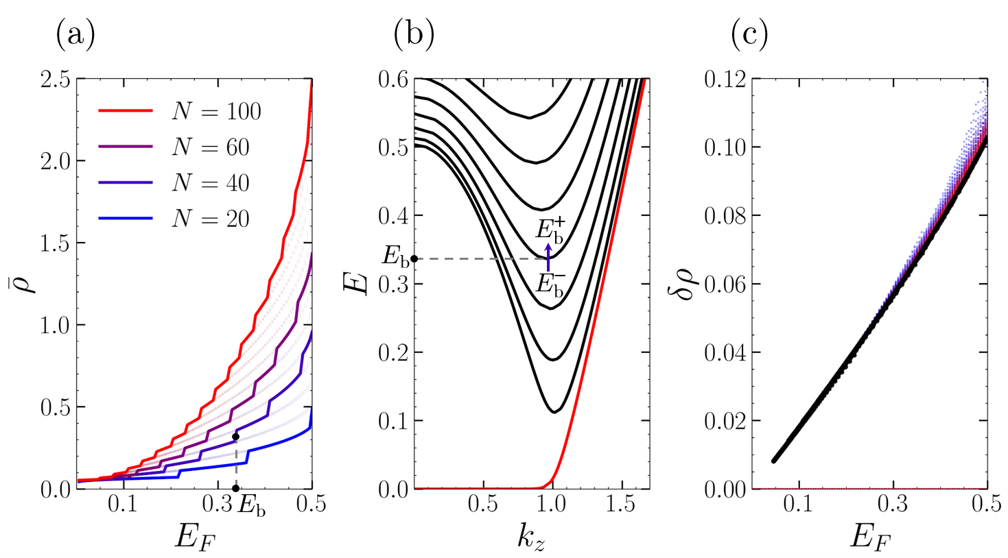
Now we would like to explain why these step surfaces happen to form clusters of curves, rather than intuitively expanding into blocky shapes as seen in other three plots. Assuming a sub-band has the bottom energy of , with the corresponding wave vector , as is shown in Fig. 4(b). Expanding the energy spectrum near the band bottom to the second order using Taylor expansion, we get
| (25) |
where are the second-order coefficients of the expansion. Since is the minimum energy of the sub-band, the first-order coefficients vanish, and are both positive. With the residue theorem, the DOS of this sub-band can be calculated as
| (26) |
where is the step function. It is worth noting that the dispersion relations of the sub-bands are distinct, so are also functions of the band bottom energy . Then we obtained the DOS jump at the bottom energy of this sub-band as
| (27) |
in which is the limit of as approaches from above or below. Since other sub-bands whose band bottoms are not have no contribute to the DOS jump at , is the jump in total DOS.
Although the sub-band bottom energies change with , the dispersion relations of the sub-bands are almost identical as long as their bottom energies are the same, regardless of the specific value of . As a result, is a function of the single variable and is approximately independent of . In Fig. 4(c), we plot all the corresponding to the band bottom energy of the sub-bands in systems with using black dots. The dense black dots are distributed near a curve, reflecting the property that is independent of .
IV Conclusion
In conclusion, we research the nonreciprocal ballistic transport in multi-layer Weyl semimetal films with surface engineering using the gauge-invariant theory. We find that the nonreciprocity comes almost entirely from the surface states while the bulk states barely have contribution. We also find that increasing thickness of the WSM film will suppress the nonreciprocity, which may be helpful for experimental discovery of significant nonreciprocal signals in the ballistic regime. Finally, we put forward a single-variable theory to explain the properties of the DOS which are roughly independent of thickness in multi-layer systems. We hope it to spark inspirations for other researchers.
Acknowledgements.
This work was supported by the State Key Program for Basic Researches of China under Grant No. 2021YFA1400403 (D. Y. X.), and the National Natural Science Foundation of China under Grants No. 11974168 (L. S.), No. 12174182 (D. Y. X.), No. 12074172 (W. C.), No. 12222406 (W. C.), No. 12274235 (R. M.), and No. 12304068 (H. G.).References
- Tokura and Nagaosa [2018] Y. Tokura and N. Nagaosa, Nature Communications 9, 3740 (2018).
- Ideue and Iwasa [2021] T. Ideue and Y. Iwasa, Annual Review of Condensed Matter Physics 12, 201 (2021).
- Rikken et al. [2001] G. L. J. A. Rikken, J. Fölling, and P. Wyder, Physical Review Letters 87, 236602 (2001).
- Krstić et al. [2002] V. Krstić, S. Roth, M. Burghard, K. Kern, and G. L. J. A. Rikken, Journal of Chemical Physics 117, 11315 (2002).
- Ideue et al. [2017] T. Ideue, K. Hamamoto, S. Koshikawa, M. Ezawa, S. Shimizu, Y. Kaneko, Y. Tokura, N. Nagaosa, and Y. Iwasa, Nature Physics 13, 578 (2017).
- Itahashi et al. [2020] Y. M. Itahashi, T. Ideue, Y. Saito, S. Shimizu, T. Ouchi, T. Nojima, and Y. Iwasa, Science Advances 6, eaay9120 (2020).
- Li et al. [2021] Y. Li, Y. Li, P. Li, B. Fang, X. Yang, Y. Wen, D.-x. Zheng, C.-h. Zhang, X. He, A. Manchon, Z.-H. Cheng, and X.-x. Zhang, Nature Communications 12, 540 (2021).
- Avci et al. [2015] C. O. Avci, K. Garello, A. Ghosh, M. Gabureac, S. F. Alvarado, and P. Gambardella, Nature Physics 11, 570 (2015).
- Yasuda et al. [2019] K. Yasuda, H. Yasuda, T. Liang, R. Yoshimi, A. Tsukazaki, K. S. Takahashi, N. Nagaosa, M. Kawasaki, and Y. Tokura, Nature Communications 10, 2734 (2019).
- Choe et al. [2019] D. Choe, M.-J. Jin, S.-I. Kim, H.-J. Choi, J. Jo, I. Oh, J. Park, H. Jin, H. C. Koo, B.-C. Min, S. Hong, H.-W. Lee, S.-H. Baek, and J.-W. Yoo, Nature Communications 10, 4510 (2019).
- Shim et al. [2022] S. Shim, M. Mehraeen, J. Sklenar, J. Oh, J. Gibbons, H. Saglam, A. Hoffmann, S. S.-L. Zhang, and N. Mason, Physical Review X 12, 21069 (2022).
- Ye et al. [2022] C. Ye, X. Xie, W. Lv, K. Huang, A. J. Yang, S. Jiang, X. Liu, D. Zhu, X. Qiu, M. Tong, T. Zhou, C.-H. Hsu, G. Chang, H. Lin, P. Li, K. Yang, Z. Wang, T. Jiang, and X. Renshaw Wang, Nano Letters 22, 1366 (2022).
- Ishizuka and Nagaosa [2020] H. Ishizuka and N. Nagaosa, Nature Communications 11, 2986 (2020).
- Yasuda et al. [2016] K. Yasuda, A. Tsukazaki, R. Yoshimi, K. S. Takahashi, M. Kawasaki, and Y. Tokura, Physical Review Letters 117, 127202 (2016).
- Kaplan et al. [2024] D. Kaplan, T. Holder, and B. Yan, Physical Review Letters 132, 26301 (2024).
- Wang et al. [2023] N. Wang, D. Kaplan, Z. Zhang, T. Holder, N. Cao, A. Wang, X. Zhou, F. Zhou, Z. Jiang, C. Zhang, S. Ru, H. Cai, K. Watanabe, T. Taniguchi, B. Yan, and W. Gao, Nature 621, 487 (2023).
- Mehraeen et al. [2023] M. Mehraeen, P. Shen, and S. S.-L. Zhang, Physical Review B 108, 14411 (2023).
- Geng et al. [2023] H. Geng, J. Y. Wei, M. H. Zou, L. Sheng, W. Chen, and D. Y. Xing, Physical Review B 107, 35306 (2023).
- Shao et al. [2024] K. Shao, H. Geng, E. Liu, J. L. Lado, W. Chen, and D. Y. Xing, Physical Review Letters 132, 156301 (2024).
- Kanagaraj et al. [2022] M. Kanagaraj, J. Ning, and L. He, Reviews in Physics 8, 100072 (2022).
- Leahy et al. [2024] I. A. Leahy, A. D. Rice, C.-S. Jiang, G. Paul, K. Alberi, and J. N. Nelson, Physical Review B 110, 54206 (2024).
- Li et al. [2020a] S. Li, G. Gu, E. Liu, P. Cheng, B. Feng, Y. Li, L. Chen, and K. Wu, ACS Applied Electronic Materials 2, 126 (2020a).
- Jia et al. [2024] K. X. Jia, R. Ma, H. Geng, L. Sheng, and D. Y. Xing, Physical Review B 109, 115306 (2024).
- Wan et al. [2011] X. Wan, A. M. Turner, A. Vishwanath, and S. Y. Savrasov, Physical Review B 83, 205101 (2011).
- Li et al. [2020b] H. Li, H. Liu, H. Jiang, and X. C. Xie, Physical Review Letters 125, 36602 (2020b).
- Morali et al. [2019] N. Morali, R. Batabyal, P. K. Nag, E. Liu, Q. Xu, Y. Sun, B. Yan, C. Felser, N. Avraham, and H. Beidenkopf, Science 365, 1286 (2019).
- Ekahana et al. [2020] S. A. Ekahana, Y. W. Li, Y. Sun, H. Namiki, H. F. Yang, J. Jiang, L. X. Yang, W. J. Shi, C. F. Zhang, D. Pei, C. Chen, T. Sasagawa, C. Felser, B. H. Yan, Z. K. Liu, and Y. L. Chen, Physical Review B 102, 85126 (2020).
- Souma et al. [2016] S. Souma, Z. Wang, H. Kotaka, T. Sato, K. Nakayama, Y. Tanaka, H. Kimizuka, T. Takahashi, K. Yamauchi, T. Oguchi, K. Segawa, and Y. Ando, Physical Review B 93, 161112 (2016).
- Sun et al. [2015] Y. Sun, S.-C. Wu, and B. Yan, Physical Review B 92, 115428 (2015).
- Zheng et al. [2023] Y. Zheng, W. Chen, X. Wan, and D. Y. Xing, Chinese Physics Letters 40, 97301 (2023).
- Zou et al. [2024] M. H. Zou, H. Geng, R. Ma, W. Chen, L. Sheng, and D. Y. Xing, Physical Review B 109, 155302 (2024).
- Varjas et al. [2018] D. Varjas, T. Ö. Rosdahl, and A. R. Akhmerov, New Journal of Physics 20, 93026 (2018).
- Christen and Büttiker [1996] T. Christen and M. Büttiker, Europhysics Letters (EPL) 35, 523 (1996).
- Jauho et al. [1994] A.-P. Jauho, N. S. Wingreen, and Y. Meir, Physical Review B 50, 5528 (1994).
- Anantram and Datta [1995] M. P. Anantram and S. Datta, Physical Review B 51, 7632 (1995).
- Datta [2005] S. Datta, Quantum Transport: Atom to Transistor (Cambridge University Press, Cambridge, 2005).
- Bruus and Flensberg [2004] H. Bruus and K. Flensberg, Many-Body Quantum Theory in Condensed Matter Physics: An Introduction (Oxford University Press, 2004).
- Wang et al. [1999] B. Wang, J. Wang, and H. Guo, Journal of Applied Physics 86, 5094 (1999).
- Buttiker [1993] M. Buttiker, Journal of Physics: Condensed Matter 5, 9361 (1993).
- Kramer [1996] B. Kramer, ed., Quantum Transport in Semiconductor Submicron Structures (Springer Netherlands, Dordrecht, 1996).
- Wang et al. [1997] J. Wang, Q. Zheng, and H. Guo, Physical Review B 55, 9763 (1997).
- Wei et al. [2022] M. Wei, B. Wang, Y. Yu, F. Xu, and J. Wang, Physical Review B 105, 115411 (2022).