PhaseMO: Future-Proof, Energy-efficient, Adaptive Massive MIMO
Abstract
The rapid proliferation of devices and increasing data traffic in cellular networks necessitate advanced solutions to meet these escalating demands. Massive MIMO (Multiple Input Multiple Output) technology offers a promising approach, significantly enhancing throughput, coverage, and spatial multiplexing. Despite its advantages, massive MIMO systems often lack flexible software controls over hardware, limiting their ability to optimize operational expenditure (OpEx) by reducing power consumption while maintaining performance. Current software-controlled methods, such as antenna muting combined with digital beamforming and hybrid beamforming, have notable limitations. Antenna muting struggles to maintain throughput and coverage, while hybrid beamforming faces hardware constraints that restrict scalability and future-proofing. This work presents PhaseMO, a versatile approach that adapts to varying network loads. PhaseMO effectively reduces power consumption in low-load scenarios without sacrificing coverage and overcomes the hardware limitations of hybrid beamforming, offering a scalable and future-proof solution. We will show that PhaseMO can achieve up to 30% improvement in energy efficiency while avoiding about 10% coverage reduction and 5dB increase in UE transmit power.
Index Terms:
massive MIMO, digital beamforming, analog beamforming, hybrid precoding, energy efficiency, future-proof, hardware complexityI Introduction
With every cellular generation, the number of antennas increase, since more antennas allows access to spatial degrees of freedom. This provides benefits like increased coverage, higher throughput and spatial multiplexing to help scale to a large number of users and exponential growth in mobile networks. At present, the most deployed multi-antenna technology is Massive MIMO, which utilizes ‘massive’ number of antennas, that can be as high as , to provide increased coverage km, net throughputs over Gbps, and ability to multiplex users in the spatial domain [1].
For considering the ease-of-deployment, most often these performance metrics (throughput, coverage) are reported when the Massive MIMO array is being fully utilized, and considered as the peak performance. As the cellular networks mature and evolve into the next generation, softwarized control over the radio hardware has emerged as an important theme [2]. Softwarized control provides greater flexibility over the hardware [3], and reduction of operational expenditure (OPEx) by tuning down the power consumption when network conditions don’t require peak performance [4]. In the context of Massive MIMO, the aim of such softwarized control is to judiciously use the massive spatial degrees of freedom to optimize for the existing network load conditions. For example, a Massive MIMO base station can reduce the number of spatially multiplexed layers under low load conditions, like night-time, and, hence save power. Further, this performance toning down should be flexible, and if needed, the underlying hardware needs to start working at the peak performance once the network load increases.
In order to make the Massive MIMO adapt to network load conditions, there are mainly two broad approaches studied in the literature: (1) Antenna muting-assisted Digital Beamformers [5] and (2) Hybrid Beamformers [6]. Majority of the existing Massive MIMO deployments utilize Digital Beamforming architecture, which has a separate digital RF chain interface for each antenna. Antenna muting approaches consist of softwarized control atop Digital Beamformers, which turns off certain number of RF chains when the network load is low. Basically, antenna muting adjusts the number of antennas as the network load varies, to improve energy efficiency by not using more than required number of antennas. However, this leads to reduced user-perceived throughput, as well as increased user-equipment power, since the overall antenna gain reduces due to muting, and this has been reported across multiple companies in latest 3GPP reports [7]. The second solution, Hybrid Beamforming (HBF) aims to always utilize the large number of antennas, while connecting them to a smaller number of RF chains via an analog network typically consisting of phase shifters. Since HBF doesn’t reduce the number of antennas, but only the number of RF chains, it doesn’t have the required drastic effect on throughput and user device power. However, HBF architectures are not flexible, and future-proof, that is, say we have a HBF that connects 64 antennas to 8 RF chains, it can not be scaled up to utilize the same hardware for 16 spatial multiplexed layers. That is, HBF architectures can only be designed for a particular network load, and are unable to scale-up if needed in future, which limits their real-world deployment.
In this work, we present PhaseMO, which enables the best elements from the prior two solutions, that is, flexible reduction of power, adaptive to network load, akin to antenna muting, and as well having the ability to use the entire antenna array like the hybrid beamformer, while reducing the RF chains. That is, in PhaseMO, the total digital compute can be optimized using software control to reduce the total number of RF chains, while always being connected to all the antennas using the proposed analog network architecture. Hence, PhaseMO maximally utilizes all the antennas’ spatial degrees of freedom to avail the maximum beamforming gain while reducing the digital processing power demanded by RF chains. This allows PhaseMO to operate at higher energy efficiencies than the existing solutions without creating any adverse effects on throughput, coverage, and user device power consumption. A summary of PhaseMO’s provided features in comparison to existing approaches is shown in Table I.
To achieve these features, PhaseMO utilizes a MIMO architecture that resembles an Analog architecture with a single RF chain and a network on phase shifters, but it differs from Analog architectures on two fronts. First, the traditional phase shifters are replaced by a Fast Phase Shifter (FPSs), which can be programmed to provide phase shifts at a sub 1 nano-second speed (Faster than 1 GHz). These FPS circuits are typically voltage controlled analog phase shifters, which are already commercially available [8]. These FPSs are used to create flexible number of ‘virtual’ RF chains, that interface a larger number of antennas (), while using only one physical RF chain. This is achieved by FPSs by creating different beams within the duration of one symbol. For example, if the bandwidth is say MHz, then the symbol time would be ns, and , then PhaseMO’s FPS would update the phase settings times faster than symbol period, i.e. every 1 ns, thus creating 10 different analog beam configurations within the net 10 ns time. This process essentially creates different beam signals within a symbol time.
The second building block of PhaseMO is a single high sampling ADC/DAC (higher than traditional Analog architecture) to digitally record the samples associated with each of the created beams. More precisely, the network of FPSs is interfaced with a single ‘physical’ RF chain, which operates at net digital conversion rate. Then, in the digital domain, the sampled signals are downsampled to the original bandwidth, while getting also de-interleaved, to effectively create virtual bandwidth RF chains, serving one beam each. Finally, these beams are then inter-mixed with a digital pre/post coder to enable times spatial multiplexing atop the created virtual RF chains carrying the analog beams. Hence, overall, by using the FPS network, PhaseMO can achieve spatial multiplexing, and as well have times analog array gain due to co-phased combining effect of the phase shifters, while digitally processing optimum net bandwidth data. This makes, PhaseMO a future-proof architecture as it allows software control to scale the number of virtual RF chains , by simply increasing the ADC/DAC sampling rate by times and running the FPSs times faster, without needing any hardware upgrades.
| Beamforming | Data Streams |
Energy
Efficiency |
Adaptability
Future-Proof |
|---|---|---|---|
| Digital | Multiple | Low | No |
| Digital + AM | Multiple | Medium | Yes |
| Hybrid |
Multiple
(Restricted) |
High | No |
| PhaseMO |
Multiple
(Unrestricted) |
High |
Yes
|
In this paper, we describe the required mathematical models to show the exact process behind the construction of these RF chains, the required approximations, analog non-idealities and their overall impact on the system performance. We show that by always utilizing the large number of antennas, PhaseMO performance matches throughput and coverage metrics of state-of-art hybrid beamformers, while capable of tuning up and down as needed. That is when , PhaseMO basically takes form of analog beamformer, and when it becomes like a digital beamformer, while any intermediary value PhaseMO emulates a hybrid beamformer. Overall, this ability to control the digital compute based on choice of makes PhaseMO energy efficient, able to reduce power consumption while not introducing any detriments towards throughput, coverage and user device power. The following sections of the paper are organized as follows: Section II discusses the related works in more detail, Section III presents the system model behind PhaseMO, Section IV then elaborates on the mathematical details of PhaseMO architecture, and Section V presents the evaluation of PhaseMO’s performance with respect to different baselines. Finally, Section VI explores additional features, limitations, and implications of this work.
II Related Work
Improving energy efficiency of wireless networks is gaining interest from both academic research [9, 10], as well as industry standards having work-items on network energy savings [7]. Researchers are actively exploring methods and techniques to reduce energy consumption by judicious use of the temporal [11, 12], frequency [13, 14], and spatial resources [15, 16] available to a radio.
In context of Massive MIMO, optimization of spatial resources is of primary importance. Here, antenna muting has emerged as an important method of reducing energy consumption, by optimizing the number of active antennas and hence the associated RF chains [5, 17, 18]. However, since antenna muting reduces number of active antennas, it also causes adverse effect on throughput and coverage, as reported by multiple companies in the network energy study by 3GPP [7]. Further, in order to reduce this adverse impact, the required antenna selection algorithms to determine which antennas to mute are not straightforward. These algorithms often involve a data-driven approach to model the network load and fine-tuning the algorithms properly to ensure that antenna muting adverse effects are reduced [19, 20, 21].
In comparison, there are alternate set of works, which utilize all the antennas, but reduce the number of RF chains instead, by using Hybrid beamforming (HBF) approaches [22, 6]. Fully-connected HBF capture maximum array gain per RF chain [23, 24], unlike the partially connected HBF [25, 26] counterparts, which only have subset of antennas connected. Hence, Fully-connected HBF increase energy efficiency by reducing the digital processing required [27, 28]. However, Fully-connected HBF is shown to have challenges in hardware implementations since they require complex analog networks with multiple splitter networks [29, 30], to ensure all the antennas are available to all the RF chains. Also, fully connected HBF can not scale up, if the number of spatial layers demanded exceeds the number of reduced RF chains, the fully connected HBF would not be able to support it. The associated hardware complexity, and inability to scale-up has limited the deployment of HBF today.
In addition to HBF, there are other proposed antenna arrays, that utilize RF switches [31, 32, 33] to multiplex multiple antennas into sharing a single RF chain using time domain codes. Most notable of these is GreenMO [31], which implements such switched-array for wideband OFDM waveforms and shows feasibility of multiple antennas sharing a single RF chain to achieve energy efficiency. However, commercially available RF switches can only reach switching speeds of ns, which limits the number of antennas that can share the same RF chain, and hence, limits the scalability of these ideas. Further, RF switches only allow for antenna-selection based beamforming gains, which fail to capture the maximum beamforming gains possible from co-phased combining across antennas. In this paper, we show how using commercially available Fast Phase Shifters (FPS) [8] can effectively lead to both, faster multiplexing to increase number of multiplexed antennas, as well efficient co-phased combining across antennas to achieve full beamforming gain.
III System Model
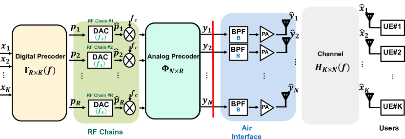
To clarify different beamforming architectures and performance, we consider a generic model that covers all existing beamforming structures, as demonstrated in Fig. 1. We will show how the architectural differences in terms of hardware implementation can differentiate the mathematical model for each of them. Based on this model, we write the mathematical expression for the signals emitted from the antennas after digital and analog precoding. For now, we do not include DAC non-idealities, as we assume they will be removed by the BPF in the air interface part.
Let there are antennas and users, and assume downlink communication, the signal emitted by antennas is given by:
| (1) |
where is the emitted signal from the antennas, is the analog precoding matrix for antennas and RF chains, is the digital precoding matrix, and is the user’s data for streams.
Now, we can discuss the model in more detail:
-
•
Baseband Digital Precoder: The precoding matrix, denoted by , performs the baseband digital precoding over different subcarriers on users’ data, denoted by the vector , which has bandwidth . This precoding produces precoded signals, each corresponding to one RF chain.
-
•
RF Chains: The precoded digital samples () are passed through RF chains, each of which includes a digital-to-analog converter (DAC) with sampling frequency and an upconverter that transforms the baseband signal to the passband (). The analog output signals are represented by and include DAC non-idealities, such as sideband images around sampling frequency products. We will discuss this in more detail later.
-
•
RF Analog Beamformer: This includes a network of phase shifters that perform the analog precoding on the passband signal. The analog precoding matrix (), which includes unity magnitude components with different phases, maps RF chains’ analog signals to signals, denoted by , which are then radiated from the antennas used in the architecture.
-
•
Air Interface Part: This section includes power amplifiers (PAs), antennas, and a bandpass filter (BPF). Positioned before the PA, the filter cleans the spectrum of non-idealities from the DAC, upconverter, and other sources. It has a bandwidth of , and is centered around . The filter operates on to produce . This configuration remains consistent across all beamforming techniques.
Finally, we can write the received signals on the user side by considering the channel effect also on the emitted signals.
| (2) |
where is the wireless channel between antennas and users. In the following subsections, we will discuss how different parts differ with respect to different beamforming techniques and how these differences affect the mathematical model for each of them.
III-1 Digital beamforming
In a digital beamforming architecture, all the precoding is performed on digital symbols, and there is no analog precoder. Consequently, there must be an equal number of RF chains and antennas. This implies , becomes identity matrix, and . Thus, we can rewrite the mathematical expression for the signals emitted from the antennas for digital beamforming using Eq. 1.
| (3) |
III-2 Analog beamforming
Analog beamformers, which are structurally different from digital beamformers, do not utilize any digital precoder. Instead, a single RF chain is employed to convert digital symbols into an analog signal, limiting the architecture to support only one user’s data transmission at a time (, , and ). This constraint significantly reduces the system’s throughput. In the analog domain, a network of phase shifters is used for precoding. This network comprises as many phase shifters as there are antennas () in the architecture, resulting in the analog precoder matrix being an vector. Therefore, the mathematical expression for the analog beamformer can be rewritten with respect to Eq. 1 as follows:
| (4) |
III-3 Hybrid beamforming
Hybrid beamforming, as the name suggests, includes both a digital precoder and an analog beamformer. Therefore, the generic structure depicted in Fig. 1 accurately represents a hybrid beamformer architecture. This architecture includes RF chains, which convert the digitally precoded symbols using into analog signals. These analog signals are then beamformed via a network of phase shifters and radiated from antennas. The analog network can be categorized into two types: a) Fully connected, and b) Partially connected. In a fully connected architecture, all RF chains are connected to all antennas. However, in the partially connected architecture, each RF chain is connected to a subset of antennas. The mathematical representation of the radiated signals from the antennas for a hybrid beamformer follows the same generic mathematical model. However, in a partially connected hybrid beamformer, only a few elements of the analog beamforming matrix are non-zero, indicating the connections between RF chains and antennas.
| (5) |
In conclusion, different hardware structure for RF chains part and the analog precoder results in different beamforming architectures. In the next section, we will show how PhaseMO can be represented as a viable alternative for all the beamforming techniques by keeping the hardware complexity similar to an analog beamforming structure.
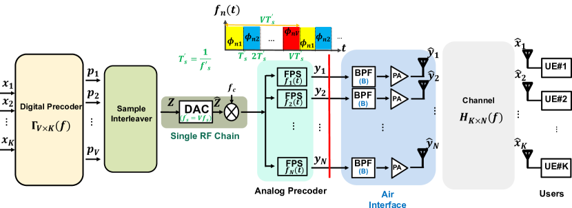
IV PhaseMO Design
PhaseMO designs a new beamforming architecture which enables high coverage area and high throughput with a single RF chain that can adapt itself to network throughput demand. In this section, we first discuss how PhaseMO mimics RF analog beamformer of traditional hybrid precoding through a simpler novel analog architecture using only single RF chain to create antenna signals in time domain. Also, we will explain how PhaseMO gains softwarized control over the radio hardware to achieve flexible throughput beating hybrid beamforming hardware limitation. Next, we will present the combining method PhaseMO uses to convert digitally precoded signals of virtual RF chains into single physical RF chain and demonstrate how it can be represented in frequency domain for further explanation on mathematical representation of the design. Finally, we will demonstrate the mathematical foundation of end-to-end communication via PhaseMO and illustrate how it has the potential to support different throughput ranges from analog beamforming to digital beamforming.
IV-A Beating hybrid beamforming’s hardwarized flexibility
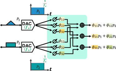
To practically realize how PhaseMO is able to generate multiple signals right after the single RF chain, and how it mimics the analog beamformer part of a traditional hybrid precoder, we consider Fig. 2. As shown in this figure, a case of three antennas with two digitally precoded signal is considered. 2.a) shows how traditional beamfomring architecture utilizes two RF chains each of which with sampling frequency and a network of phase-shifters (PSs) to create three signals for radiation from the antennas. In this figure, we can see each RF chain is connected to all three antennas, and the signals which get radiated from the antennas are summation of two phase shifted RF chains signals which are produced via time invariant PSs.
On the other hand, as shown in Fig. 2.b), PhaseMO uses only single RF chain with two times more sampling frequency to convert digitally interleaved signals into single analog signal which goes into FPSs each of which has individual phase control and works at DAC sampling frequency speed with period of . As shown in Fig. 2, by configuring the FPSs to shift the phase of signals in a specific pattern, we can exactly create the same signal produced in Fig. 2.a).
Furthermore, we can see if we had more number of digitally precoded signals (deamand for more throughput), we could easily combine them to pass through the single physical RF chain with an increased sampling frequency proportionate to the number of precoded signals (Fig. 2.b). However, we need to increase the number of physical RF chains in traditional hybrid beamforing architecture to be able to achieve more degrees of freedom on digital beamforming or multiplexing more number of beams.
IV-B How to combine multiple precoded signals to use single RF chain
Here, we are discussing how combining digitally precoded signals will affect the spectrum and how it can be represented mathematically. As later on, we have to consider effect of a bandpass filter on the radiated signal, we do the mathematical analysis of this part in frequency domain.
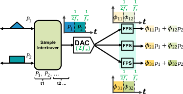
As shown in Fig. 3, if we denote as the number of digitally precoded symbols, we can combine all precoded data into one signal using a sample interleaver. So, we can write the time domain interpretation of the interleaved signal denoted by .
| (6) |
where denotes the -th sample of the -th digitally precoded time-domain vector (virtual RF chain).
Thus, we can write down the frequency domain representation of sample interleaver output as follows:
| (7) |
where represents the frequency-domain phase shift due to the time-domain delay for -th precoded symbol vector.
To complete the sequence of components and their effects on the signal, we also demonstrate the effect of DAC on the signal’s spectrum which is a major issue that needs to be evaluated as we are using time-variant phase shifters which can also create other side bands. Although the DAC’s effect depends on the type of operation technology on which DAC works, we can generally consider that the DAC output creates side band spectrums of the main signal at sampling frequency products with a sinc roll-off factor. For example, if we assume the DAC is working at sampling frequency on a signal with bandwidth, that will create sidebands at products of each of which with bandwidth.
Therefore, if we consider as the over-the-air bandwidth in our architecture, Eq. 7 clearly shows that the signal bandwidth won’t change due to interleaving, and we can write the DAC output spectrum considering function which models the non-idealities come from the DAC.
| (8) |
where is the DAC output signal in frequency domain.
IV-C Mathematical representation of PhaseMO
By explaining two previous parts, here, we want to close the loop and unify the mathematical representation of the PhaseMO architecture. For this purpose, we consider antennas, users, and denotes the number of virtual RF chains.
First, we define the signal generated by a single FPS over one period. This can be modeled as a summation of shifted pulses with constant phases:
| (9) |
where is the time-variant signal produced by the FPS at the -th antenna, and is the -th phase produced by the -th antenna FPS.
Next, we extend to account for its periodic nature:
| (10) |
Here, represents the duration of one period, and is the DAC sampling frequency of PhaseMO with respect to other beamfromings sampling frequency(). Also demonstrates a pulse with width of . To convert the time-domain signal to the frequency domain, we break the time-domain signal to the convolution of the pulse with an impulse train:
| (11) |
The frequency-domain representation of can then be derived as:
| (12) |
Now, we present the end-to-end mathematical derivation of PhaseMO’s architecture, incorporating the previously discussed components. First, we express the time-domain signal at the output of the FPS and then derive its corresponding frequency-domain representation:
| (13) |
Here, and are derived in Eqs. (8) and (12), respectively. Substituting these into the expression gives:
| (14) |
This expression indicates that the final spectrum, which will be passed through bandpass filters, includes the DAC output spectrum and a shifted versions of that, resulting from the time-variant phase-shifters’ effect. The bandpass filter will remove all the sidebands out of bandwidth centered at , so we need to determine the exact output of the filter.
DAC image artifacts are located at frequencies. For values of that are multiples of (), these images will be shifted into the band that the bandpass filter will pass. Consequently, the output of the bandpass filter can be determined as:
| (15) |
which represents the filters output frequency domain signal. For all , the expression evaluates to zero, and for , we have . Therefore:
| (16) |
Replacing using Eq. (7), we can achieve the signal radiated from the antennas:
| (17) |
By considering we can express the summation in matrix form:
| (18) |
which represents the phase matrix represented by FPSs each of which has period. Furthermore, we can also include digital precoding matrix denoted by in this part to clarify the final radiated signal on the user side ():
| (19) |
Finally, if we consider channel, we can figure out what signal will be received on the user side that can be written as follows:
| (20) |
We now aim to further explain the equation derived for the signal emitted from the antennas and discuss how PhaseMO can relate to the other beamforming techniques mentioned earlier. For this, we refer to Eq. 19.
-
•
V=N: In this case, the final equation can be written as follows:
(21) This equation is exactly similar to what we already derived for a digital beamformer, which uses the same number of RF chains and antennas (Eq. 2)
-
•
V=1: In this case, the final equation can be written as follows:
(22) We can observe that this equation is in the same form as that for an analog beamformer, which uses just one RF chain (Eq. 3). This shows that PhaseMO with can model an analog beamformer.
-
•
V=R: In this case, where we consider as a number that can model the hybrid beamforming architecture, the final equation can be written as follows:
(23) This equation aligns with the form we have for a hybrid beamformer. It shows that PhaseMO with can model a hybrid beamformer.
Although the mathematical description assumes PhaseMO in a downlink scenario, by considering a ADC instead of DAC, and performing the desired interleaving, similar expressions can be derived for uplink scenario as well. In conclusion, PhaseMO with just a single RF chain can adapt itself to different network throughput in a softwarized manner.
V Evaluation
So far, we have explained the design of the new beamforming architecture, PhaseMO, its operation, and its mathematical representation. In this section, we will discuss various simulation experiments conducted to verify PhaseMO’s design and demonstrate its key application: load-adaptable power consumption while maintaining good throughput. First, we will describe the evaluation setting. Then, we will compare PhaseMO’s throughput with various baselines, including digital beamforming (DBF), fully connected hybrid beamforming (HBF), partially connected hybrid beamforming, analogue beamfoming (ABF), and GreenMO. We will also examine how PhaseMO achieves reasonable energy efficiency by adapting to network traffic while maintaining coverage area and UE transmit power consumption. Additionally, we will compare PhaseMO’s adaptability with antenna muting combined with digital beamforming as the baseline.
V-1 Evaluation setting
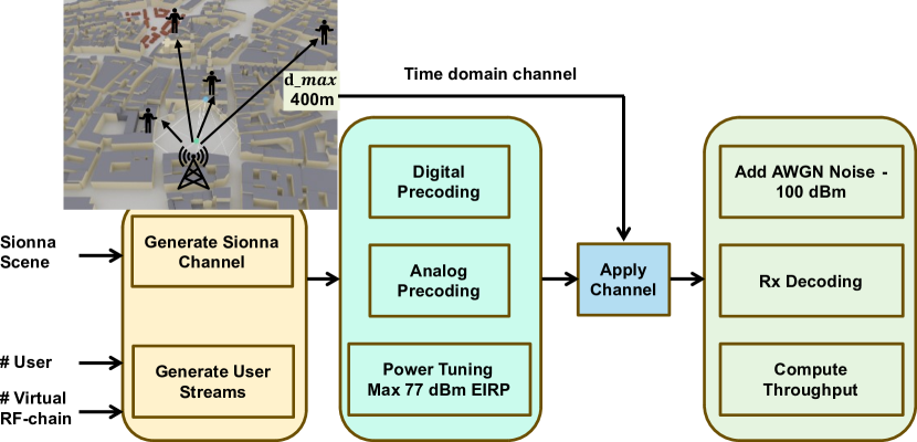
To evaluate PhaseMO, we utilize the frequency channel derived from Sionna, a GPU-accelerated open-source library for link-level simulations based on TensorFlow. Sionna generates the channel frequency response in an open environment model that includes buildings of various sizes. In this study, we set up a base station at a height of meters, equipped with antennas, and consider the distribution of single-antenna users at varying distances from the base station in provided Munich map. Specifically, we place one user randomly at a certain distance from the base station, ensuring that the remaining users are located within a distance less than . Sionna identifies all beams that can reach the users from the base station and determines the channel impulse response, which includes multiple taps with different phases and attenuation. Finally, it obtains the channel information for each subcarrier based on defined parameters such as center frequency, number of subcarriers, and subcarrier spacing. This configuration is repeated 10 times for each , as shown in Fig. 4 for a case of 4 users. The evaluation setup as shown in Fig. 4, allows us to comprehensively evaluate PhaseMO in a realistic over-the-air wireless channel scenario.
As shown in Fig. 4, we use the Sionna channel frequency response in the MATLAB simulation platform to implement different beamforming techniques. Initially, the random users’ data are precoded digitally in orthogonal frequency division multiplexing (OFDM) symbols, each with a MHz bandwidth, assuming perfect channel estimation. Then, the OFDM symbols, after conversion to the time domain, pass through the analog phase-shifter network (i.e., analog or hybrid beamforming). Finally, the radiated signal from each antenna is amplified for over-the-air transmission conditioned not violating maxEIRP of dBm limit .
On the user side, Additive White Gaussian Noise (AWGN) with dBm power is considered to determine the SNR for each user. The SNR is then converted using a modulation and coding scheme (MCS) table to obtain the spectral efficiency and net throughput.
V-2 Throughput evaluation
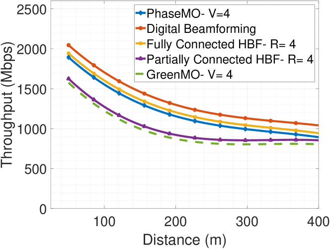
Here, we evaluate PhaseMO in terms of net throughput with other beamforming techniques including DBF, fully connected HBF, partially connected HBF, ABF, and GreenMO. As discussed earlier, to calculate the spectral efficiency (SE) in bps/Hz for each user, we use the 5G-NR modulation and coding scheme (MCS) table to convert SNR (Signal to Noise Ratio) to SE for each user. We then sum the spectral efficiency of all users and consider total bandwidth in-use to obtain the system net throughput. We repeat this procedure for different distances from the base-station. In Fig. 5, PhaseMO’s net throughput which employs virtual RF chains with 64 antennas comparing to other baselines for users is shown. It can be observed that the PhaseMO net throughput is a little bit lower than fully-connected HBF accounting for lower SNR due to bandpass filter insertion loss, and also it can be observed partially connected HBF and GreenMO with approximately same throughput stand below PhaseMO as mentioned in [31].
V-3 Adaptability evaluation:
To evaluate the adaptability feature of PhaseMO, we analyze throughput degradation and power decrease while reducing the number of virtual RF chains. On the other hand, we evaluate the same metrics while using antenna muting combined with digital beamofming (AM +DBF). Finally, combining the power and throughput evaluation, we show how reducing the number of physical RF chains in AM +DBF or virtual RF chains in PhaseMO will affect the energy efficiency (EE) in different load scenarios. As well as this, we show how coverage area and UE transmit power will get affected in AM + DBF.
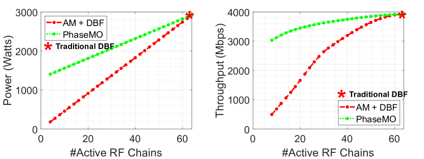
Power consumption for different number of unmuted/ virtual RF chains with respect to a traditional 64-antenna BS is shown in Fig. 6.a). For a traditional DBF architecture, total power consumption of a base-station is mostly dominated by PAs and base-band processing power consumption. PA power consumption can be calculated based on the number of unmuted RF chains, PA’s output power which is defined based on the max EIRP limit, and PA’s efficiency, here, we consider % power efficient PAs ([34]) and put the output power of each PA based on maxEIRP of dBm. On the other hand, base-band power consumption can be evaluated using [35] and [36]. We consider GFLOPS for each number of unmuted/virtual RF chains each of which requires W. So, we can compute the BS power consumption taking into account PAs’ power consumption and base-band power consumption.
Taking advantage of AM+DBF to mitigate this power consumption, as we reduce the number of active physical RF chains, both PA power consumption and base-band processing power will drop; however, due to reducing the number of active PAs in the architecture, and multiplexing gain, the system’s net throughput will be reduced as well (Fig. 6.b). On the other hand, in PhaseMO similar to hybrid beamforming, if we reduce the number of virtual RF chains, we gain only from reducing the base-band processing power consumption while maintaining all the PAs active which won’t cause any throughput reduction.
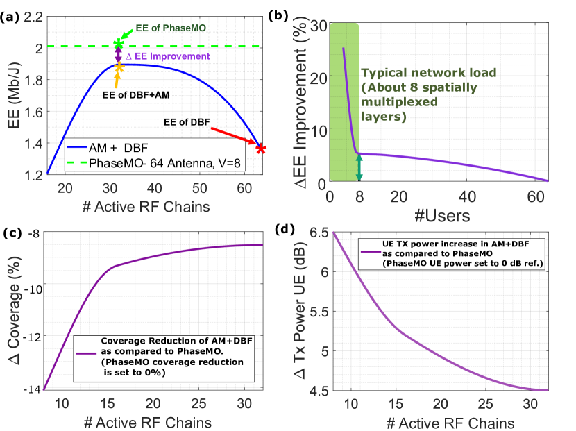
Therefore, we can evaluate which technique works better in terms of saving power while keeping a reasonable throughput, thus we use energy efficiency () which combines both of these parameters together. As shown in Fig. 7.a) for a network with number of users, using PhaseMO with constant number of virtual RF chains maintain energy efficiency higher than the the optimum operation point of AM+DBF is when half of the BS RF chains ( out of ) are muted, Consequently, as shown this reulst in Fig. 7.b) for different number of users, as we increase the number of users up to which is typical number of users connected to today’s mMIMO BSs, due to less throughput gain of PhaseMO with respect to AM+DBF, the EE improvement gain for PhaseMO in comparison with the best operating point for AM+DBF will reduce to 5% which still is promising.
Although 5% does not look a promising improvement if we replace AM+DBF with PhaseMO for a case of 8 users, PhaseMO can be considered a better adaptive solution if we include other performance metrics such as coverage area and UE transmit power in uplink. As shown in Fig. 6.b), AM+DBF loses more throughput while trying to achieve a low power consumption due to turning of some of the antennas and reducing the multiplexity gain. Therefore, it also reduces the coverage area on one side, and on the other side, it makes UE devices to draw more power to achieve the same throughput in uplink; however, since PhaseMO just loses some throughput due to less number of virtual RF chains, it won’t affect the coverage area and UE transmit power.
To verify these two results a shown in Fig. 6.c), if we consider the base-station coverage map with 64 antennas as the baseline in Sionna, due to reducing the number of RF chains the coverage area will decrease and it even reaches about 14% coverage reduction. Additionally, considering the same base-line if we randomly distribute users in the base-station coverage area, the average transmit power of the user will increase by 4.5dB at the best case and 6.5dB at the worst case. As a result, PhaseMO guarantees worst case coverage and throughput requirements while improving energy efficiency of the network. This is achieved by designing an architecture that always uses maximum number of antennas while flexibly cutting down on digital processing power.
VI Discussion and Limitations
In this section, we examine the implications of the PhaseMO architecture, acknowledging its limitations and providing insights for future research and potential enhancements.
-
•
Scaling to Higher Number of Antennas: While PhaseMO leverages a single RF chain, hardware constraints such as high DAC sampling frequency and fast FPSs, along with design limitations like power spreading due to FPSs, restrict scalability beyond 64 antennas.
-
–
Sampling Frequency: The highest ADC/DAC sampling frequency available in the market is currently 6.4 Gsps [37]. This DAC can support up to 64 antennas in PhaseMO considering MHz over-the-air bandwidth.
-
–
Phase Shifter Bandwidth: PhaseMO employs high-speed ADC/DACs and FPSs operating at the same rate. At present, the modulation bandwidth of FPS chosen is 2.5 GHz [8] which allows up to 24 antennas to be interfaced with the existing circuit. Further research can be enabled to achieve faster FPS, and as well alternately, future architectures can utilize other circuits, like mixers, with LO phase offsets to achieve faster modulation bandwidths.
-
–
Power Spreading: As detailed in Section IV, FPSs spread the signal power across the spectrum, attenuating the main band signal’s power by . Therefore, small PAs are required before the larger PA, which provides up to 47 dB gain, limiting support to up to 128 users under these conditions.
-
–
-
•
Handling Out-of-Band Emission: Due to the spectral spreading effect of FPSs, employing high-precision bandpass filters is essential to reduce ACPR. These filters must be narrowband (100 MHz) with high out-of-band attenuation. The non-ideal characteristics of these filters can exacerbate interference.
-
•
Channel Estimation compliance with PhaseMO: The 5G standard for MIMO based channel estimation at present assumes one antenna mapped to one digital port for channel estimation, which makes it difficult to integrate architectures like PhaseMO, and as well hybrid beamformers. However, there are new changes proposed in release 18 and beyond [38], like orthogonal cover codes can enable more antennas channel from fewer ports, which can make PhaseMO compliant with 5G.
VII Conclusion
PhaseMO provides a solution to scaling Massive MIMO power consumption flexibly based on network load, while not causing any adverse effect on performance metrics like coverage, throughput and user-device power. This is enabled by a new proposed architecture that utilizes Fast Phase Shifters (FPS), capable of providing full array beamforming gain, while reducing the digital interfacing required to optimum levels necessitated by network load conditions. By capturing the full array gain and optimizing for the digital interfacing, PhaseMO can achieve % better energy efficiency, while keeping performance metrics like coverage and user throughput to the desired peak level of a fully utilized Massive MIMO array.
References
- [1] Samsung Networks. Whitepaper: Samsung delivers the promises of massive mimo.
- [2] Mao Yang, Yong Li, Depeng Jin, Li Su, Shaowu Ma, and Lieguang Zeng. Openran: a software-defined ran architecture via virtualization. ACM SIGCOMM computer communication review, 43(4):549–550, 2013.
- [3] Xavier Costa-Pérez, Joerg Swetina, Tao Guo, Rajesh Mahindra, and Sampath Rangarajan. Radio access network virtualization for future mobile carrier networks. IEEE Communications Magazine, 51(7):27–35, 2013.
- [4] Peter Rost, Ignacio Berberana, Andreas Maeder, Henning Paul, Vinay Suryaprakash, Matthew Valenti, Dirk Wübben, Armin Dekorsy, and Gerhard Fettweis. Benefits and challenges of virtualization in 5g radio access networks. IEEE Communications Magazine, 53(12):75–82, 2015.
- [5] Pål Frenger and Ke Wang Helmersson. Massive mimo muting using dual-polarized and array-size invariant beamforming. In 2021 IEEE 93rd Vehicular Technology Conference (VTC2021-Spring), pages 1–6. IEEE, 2021.
- [6] Roi Méndez-Rial, Cristian Rusu, Nuria González-Prelcic, Ahmed Alkhateeb, and Robert W Heath. Hybrid mimo architectures for millimeter wave communications: Phase shifters or switches? IEEE access, 4:247–267, 2016.
- [7] 3gpp study on network energy saving. https://portal.3gpp.org/desktopmodules/Specifications/SpecificationDetails.aspx?specificationId=3987.
- [8] Analog Devices Inc. Eval01-hmc877lc3 evaluation board, 2024. Accessed: 2024-07-31.
- [9] Shuangfeng Han, Sen Bian, et al. Energy-efficient 5g for a greener future. Nature Electronics, 3(4):182–184, 2020.
- [10] Emil Björnson and Erik G Larsson. How energy-efficient can a wireless communication system become? In 2018 52nd Asilomar conference on signals, systems, and computers, pages 1252–1256. IEEE, 2018.
- [11] Kaiwei Wang, Wuyang Zhou, and Shiwen Mao. Energy efficient joint resource scheduling for delay-aware traffic in cloud-ran. In 2016 IEEE Global Communications Conference (GLOBECOM), pages 1–6. IEEE, 2016.
- [12] Lopamudra Kundu, Xingqin Lin, and Rajesh Gadiyar. Towards energy efficient ran: From industry standards to trending practice. arXiv preprint arXiv:2402.11993, 2024.
- [13] Sihyun Choi, Siyoung Choi, Goodsol Lee, Sung-Guk Yoon, and Saewoong Bahk. Deep reinforcement learning for scalable dynamic bandwidth allocation in ran slicing with highly mobile users. IEEE Transactions on Vehicular Technology, 2023.
- [14] Yaser Azimi, Saleh Yousefi, Hashem Kalbkhani, and Thomas Kunz. Energy-efficient deep reinforcement learning assisted resource allocation for 5g-ran slicing. IEEE Transactions on Vehicular Technology, 71(1):856–871, 2021.
- [15] Stefan Wesemann, Jinfeng Du, and Harish Viswanathan. Energy efficient extreme mimo: Design goals and directions. IEEE Communications Magazine, 2023.
- [16] David López-Pérez, Antonio De Domenico, Nicola Piovesan, Geng Xinli, Harvey Bao, Song Qitao, and Mérouane Debbah. A survey on 5g radio access network energy efficiency: Massive mimo, lean carrier design, sleep modes, and machine learning. IEEE Communications Surveys & Tutorials, 24(1):653–697, 2022.
- [17] Ranjini Guruprasad and Sujit Dey. User qos-aware adaptive rf chain switching for power efficient cooperative base stations. IEEE Transactions on Green Communications and Networking, 1(4):409–422, 2017.
- [18] Javed Akhtar, Ketan Rajawat, Vipul Gupta, and Ajit K Chaturvedi. Joint user and antenna selection in massive-mimo systems with qos-constraints. IEEE Systems Journal, 15(1):497–508, 2020.
- [19] Selcuk Bassoy, Rasoul Behravesh, and Joan Pujol-Roig. Seedrl: Smart energy efficiency using deep reinforcement learning for 6g networks. In 2023 IEEE Globecom Workshops (GC Wkshps), pages 732–737. IEEE, 2023.
- [20] Nuwanthika Rajapaksha, Jafar Mohammadi, Stefan Wesemann, Thorsten Wild, and Nandana Rajatheva. Minimizing energy consumption in mu-mimo via antenna muting by neural networks with asymmetric loss. IEEE Transactions on Vehicular Technology, 2023.
- [21] Fazel Haq Ahmadzai and Woongsup Lee. Adaptive antenna muting using rnn-based traffic load prediction. Journal of the Korea Institute of Information and Communication Engineering, 26(4):633–636, 2022.
- [22] Thomas Kühne, Piotr Gawłowicz, Anatolij Zubow, Falko Dressler, and Giuseppe Caire. Bringing hybrid analog-digital beamforming to commercial MU-MIMO wifi networks. In Proceedings of the 26th Annual International Conference on Mobile Computing and Networking, pages 1–3, 2020.
- [23] Susnata Mondal, Rahul Singh, and Jeyanandh Paramesh. 21.3 a reconfigurable bidirectional 28/37/39GHz front-end supporting MIMO-TDD, carrier aggregation TDD and FDD/Full-duplex with self-interference cancellation in digital and fully connected hybrid beamformers. In 2019 IEEE International Solid-State Circuits Conference-(ISSCC), pages 348–350. IEEE, 2019.
- [24] Susnata Mondal, Rahul Singh, Ahmed I Hussein, and Jeyanandh Paramesh. A 25–30 GHz fully-connected hybrid beamforming receiver for MIMO communication. IEEE Journal of Solid-State Circuits, 53(5):1275–1287, 2018.
- [25] Hong-Teuk Kim, Byoung-Sun Park, Seong-Sik Song, Tak-Su Moon, So-Hyeong Kim, Jong-Moon Kim, Ji-Young Chang, and Yo-Chul Ho. A 28-GHz cmos direct conversion transceiver with packaged 2*4 antenna array for 5G cellular system. IEEE Journal of Solid-State Circuits, 53(5):1245–1259, 2018.
- [26] Xiufeng Xie, Eugene Chai, Xinyu Zhang, Karthikeyan Sundaresan, Amir Khojastepour, and Sampath Rangarajan. Hekaton: Efficient and practical large-scale MIMO. In Proceedings of the 21st Annual International Conference on Mobile Computing and Networking, pages 304–316, 2015.
- [27] Yongce Chen, Yan Huang, Chengzhang Li, Y Thomas Hou, and Wenjing Lou. Turbo-HB: A novel design and implementation to achieve ultra-fast hybrid beamforming. In IEEE INFOCOM 2020-IEEE Conference on Computer Communications, pages 1489–1498. IEEE, 2020.
- [28] Xianghao Yu, Juei-Chin Shen, Jun Zhang, and Khaled B Letaief. Alternating minimization algorithms for hybrid precoding in millimeter wave MIMO systems. IEEE Journal of Selected Topics in Signal Processing, 10(3):485–500, 2016.
- [29] Han Yan, Sridhar Ramesh, Timothy Gallagher, Curtis Ling, and Danijela Cabric. Performance, power, and area design trade-offs in millimeter-wave transmitter beamforming architectures. IEEE Circuits and Systems Magazine, 19(2):33–58, 2019.
- [30] C Nicolas Barati, Sourjya Dutta, Sundeep Rangan, and Ashutosh Sabharwal. Energy and latency of beamforming architectures for initial access in mmwave wireless networks. Journal of the Indian Institute of Science, 100(2):281–302, 2020.
- [31] Agrim Gupta, Sajjad Nassirpour, Manideep Dunna, Eamon Patamasing, Alireza Vahid, and Dinesh Bharadia. Greenmo: Enabling virtualized, sustainable massive mimo with a single rf chain. In Proceedings of the 29th Annual International Conference on Mobile Computing and Networking, pages 1–17, 2023.
- [32] Grzegorz Bogdan, Konrad Godziszewski, and Yevhen Yashchyshyn. Time-modulated antenna array for real-time adaptation in wideband wireless systems–part ii: Adaptation study. IEEE Transactions on Antennas and Propagation, 68(10):6973–6981, 2020.
- [33] José P González-Coma and Luis Castedo. Wideband hybrid precoding using time modulated arrays. IEEE Access, 8:144638–144653, 2020.
- [34] K. Kim, T. Lee, and M. Kim. High efficiency power amplifiers for rf and microwave applications. IEEE Transactions on Microwave Theory and Techniques, 68(10):3220–3230, October 2020.
- [35] Ligia Maria Moreira Zorello, Marco Sodano, Sebastian Troia, and Guido Maier. Power-efficient baseband-function placement in latency-constrained 5g metro access. IEEE Transactions on Green Communications and Networking, 6(3):1683–1696, 2022.
- [36] Emil Björnson, Erik G Larsson, and Thomas L Marzetta. Massive mimo: Ten myths and one critical question. IEEE Communications Magazine, 54(2):114–123, 2016.
- [37] Analog Devices. Ad9162: Dual-channel, 16-bit, 6.4 gsps dac with high-speed digital interface, 2024. Accessed: 2024-07-31.
- [38] Huangping Jin, Kunpeng Liu, Min Zhang, Leiming Zhang, Gilwon Lee, Emad N Farag, Dalin Zhu, Eko Onggosanusi, Mansoor Shafi, and Harsh Tataria. Massive mimo evolution toward 3gpp release 18. IEEE Journal on Selected Areas in Communications, 41(6):1635–1654, 2023.