How soap bubbles change shape while maintaining a fixed volume of air?
Abstract
We combine experiments and theoretical derivations to study the evolution of a stretched soap bubble and compare it with an open film to highlight the effect of volume conservation. There exists a critical length for both surfaces beyond which the bottleneck developed in their middle starts to shrink irreversibly and pinch off into multiple compartments. Before the system leaves the regime of equilibrium, the minimization of surface energy plays a major role in determining its shape, which can be tackled by the variational method theoretically. In contrast to open films, soap bubble volume conservation introduces a Lagrange multiplier that plays the role of pressure difference in mediating the evolution of bubble shape over a long range. By examining how boundary constraints influence bubble deformation, we establish a framework contrasting the bubble’s convex-to-concave transition with the behavior of soap films under similar conditions. Using experiments and theoretical modeling, we analyze the equilibrium and breakup regimes, providing insight into the role of geometric constraints on surface tension-driven systems. Our findings reveal critical differences between bubble and film stability profiles, shedding light on universal behaviors in non-equilibrium fluid mechanics and potential applications across biological and material sciences.
I Introduction
The study of how droplets change their surfaces under different boundary conditions and what shape they adopt to minimize their surface energy while maintaining a fixed internal volume has deep historical roots in the field of variational calculus Leonhard (1744); Goldstine (1980). The concept can be traced back to the 18th century, prominently featured in the works of Euler and Lagrange who laid the foundational principles. Without the constraint of volume conservation, the problem is simple with the first successful example by Plateau Plateau (1857) on the profile of open soap films.
The role of surface tension, or equivalently minimization of surface in liquid, is crucial in many fields. Applications include (1) Biology: the structure of cell membranes that directly affects the activity of membrane-bound proteins. Building models for the dynamics of membranes is a crucial step in finding the mechanism behind the formation of the membrane structure. All of these models require minimizing the surface energy to stabilize the membrane structure, especially during the phase transition. (2) Chemical engineering: Help predict the structures and behaviors of colloidal membranes composed of rod-like viruses. Modifying the boundary conditions can change their shape from a catenoid to tethers under external forces. (3) Material science: For metal crystals in zeolites and other porous materials, surface tension dictates the arrangement of atoms to stabilize the structure.
However, pure academic studies include the recent highlight of the fundamental role of catenoids and helicoids for equilibrium systems. Dimensional reduction to a one-dimensional Schrödinger operator has simplified the analysis of unstable modes Alexander and Machon (2020). Additionally, it has been shown that all minimal surfaces can be constructed from pieces of helicoids and catenoids Colding and Minicozzi (2006). Combining theoretical proofs with numerical methods, the existence and properties of the genus-one helicoid have also been established by assuming periodic boundary conditions and employing the intermediate value theorem Weber, Hoffman, and Wolf (2005).
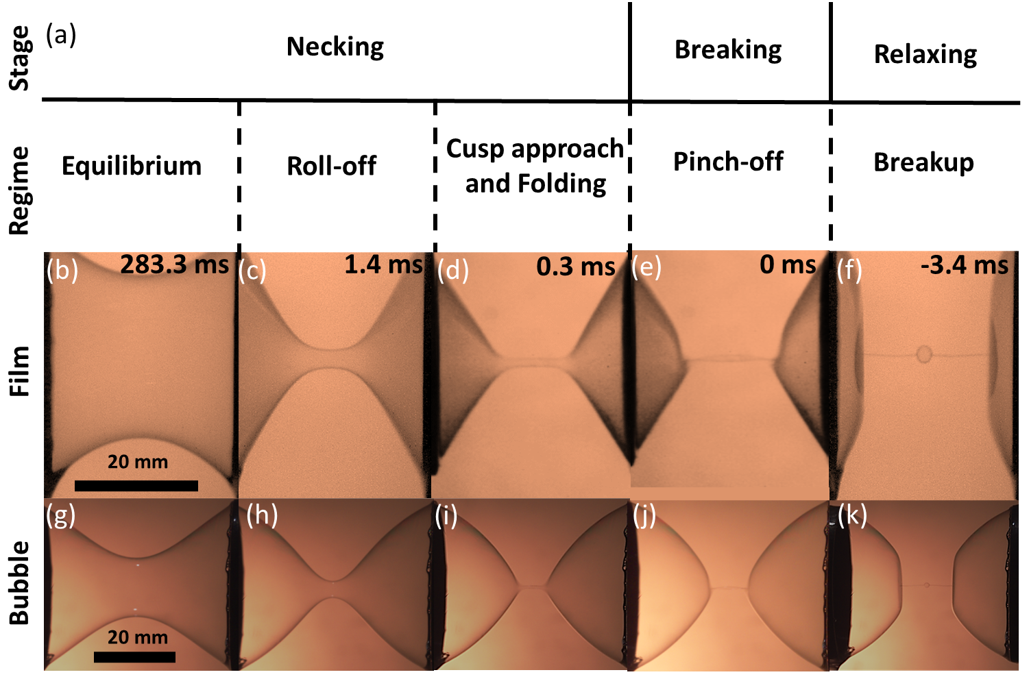
Blowing soap bubbles is a childhood experience shared by most people. When the bubbles are stretched to some critical length, the bottleneck developed at their middle starts to shrink spontaneously. A notable outcome of this out-of-equilibrium process is the pinch-off when the fluid breaks into smaller compartments, which is of practical importance in industrial applications such as inkjet printing Abdolmaleki, Kidmose, and Agarwala (2021) and injection molding Agrawal, Pandelidis, and Pecht (1987). It can even offer insight into biological processes, such as animal cell division Yoon (2001). Since this study focuses on long-range mediation of internal pressure due to volume conservation, we will concentrate on systems for which the surface tension dominates the viscous stress in influencing the dynamics of such a singularity. Examples include thin films Goldstein et al. (2021); Cheng et al. (2021), droplets Dussan V (1975); Lister and Stone (1998); Ting and Keller (1990); Peregrine, Shoker, and Symon (1990); Eggers (1993); Schulkes (1994); Brenner, Shi, and Nagel (1994); Eggers and Dupont (1994); Shi, Brenner, and Nagel (1994); Kowalewski (1996); Zhang and Stone (1997); Wilkes, Phillips, and Basaran (1999); Notz, Chen, and Basaran (2001); Ambravaneswaran, Wilkes, and Basaran (2002); Lee, Lowengrub, and Goodman (2002); Subramani et al. (2006); Xu and Basaran (2007); Eggers and Villermaux (2008); Huang, Pan, and Josserand (2019); Cohen et al. (1999); Zhang and Lister (1999); Cohen and Nagel (2001); Sierou and Lister (2003); Dinic and Sharma (2019); Lagarde, Josserand, and Protière (2018); Burton, Rutledge, and Taborek (2007), air bubbles Keller (1983); Bergmann et al. (2006), and ligaments Villermaux, Marmottant, and Duplat (2004) where universal power laws are known to dictate the inviscid fluid behavior. Numerical and theoretical studies Chen and Steen (1997); Day, Hinch, and Lister (1998) have confirmed the universality of these power laws. For example, Chen and Steen Chen and Steen (1997) demonstrated a power-law fit of with an exponent of during pinch-off. This prediction was later experimentally validated by Robinson and Steen Robinson and Steen (2001); Cryer and Steen (1992), although they fell short of exploring the final behavior right before the breakup due to the limited frame rate of their high-speed camera.
The minimization of surface energy also plays a significant role in the evolution of systems at non-equilibrium. For instance, in axisymmetric membranes with areas exceeding the critical threshold, additional cylindrical tether solutions appear, making it possible to remain in equilibrium at increasingly large ring separations Jia et al. (2021). Understanding fluid behaviors in the pre-pinch-off regime, where instabilities in the catenoidal shape lead to a universal cone angle, is a crucial point focused in previous studies Goldstein et al. (2021). During the collapse of catenoidal soap films, a unique geometric transition occurs, where two acute-angle cones are formed and connected to the supporting rings, joined by a central quasi-cylindrical region before the final pinch-off event.
The stability of soap membranes plays a crucial role in the study of two-dimensional flow. Traditionally, the lifespan of these membranes is prolonged by reducing the evaporation rate of the soap water, achievable by adding glycerol Boulogne, Restagno, and Rio (2022). Frazier et al. Frazier, Jiang, and Burton (2020) have provided a quantified analysis of the role of long-chain polymers in the solution. Their findings bridge the gap between the effects of extensional rheology and the longevity of the membrane. In the meantime, Pasquet et al.Pasquet et al. (2022) offers a more detailed recipe, indicating the optimal ratio of surfactants, lubricants, and glycerol.
The breakage of liquid stored between the gap of two horizontally and vertically separated rods has been studiedAhmed, Sung, and Kim (2011); Slobozhanin and Perales (1993); Galaktionov, Galaktionova, and Tropp (2020); Papageorgiou (1995); Zhang, Padgett, and Basaran (1996). It was observed that the volume of the liquid influenced ; however, their conclusions were affected by the movement of the contact line Darhuber, Troian, and Wagner (2001) during neck collapse and the deviation from gravity in horizontal and vertical experiments.
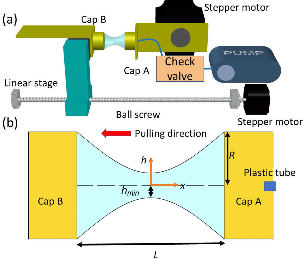
The appeal of soap bubbles as a research subject lies in their simplicity and accessibility. Following this principle, the theoretical studies of our work are accompanied and backed up by experiments. Therefore, it is necessary to mention two technical details. First, the artifacts from gravity can be neglected by stretching a soap bubble horizontally. This is the place a third way of approach enters, i.e., we numerically calculate the profile of the soap bubble to show that the deviation due to gravity is indeed negligible because of the thin membrane of the bubble. Second, both the soap bubble and its boundaries at both ends are hollow. The motion of the soap water on the boundary is limited by the thickness of the hollow boundary caps.
II Experimental setup
Our soap water contains the following ingredients: soap made from dried oleic acid, filtered water, and powdered guar gum. The addition of guar gum has been verified to prolong the lifetime of the soap membrane Frazier, Jiang, and Burton (2020). Following immersion in the solution, an aluminum cap A with a radius of is rotated by 90 degrees using a stepper motor to horizontally align its open end with cap B, which is positioned at a distance of . When the air pump is activated using a solid-state relay module, a soap bubble is generated on cap A. To prevent deflation of the bubble, we incorporate a check valve to ensure that no air backflow occurs. As demonstrated schematically in Fig. 2, this bubble is gently attached to cap B that is pre-wetted. Next, cap B is moved away from cap A using a linear ball screw driven by another stepper motor. The pulling speed is maintained at a constant value of approximately mm/s. The collapse of the bubble neck is captured by a high-speed camera operating at 23000 fps. It is worth mentioning that the soap film was originally prepared by drilling a big hole in cap B to allow the air to flow freely out of the membrane. However, it turned out that the close surface of cap A introduced asymmetry to the airflow that consequently distorts the shape of the soap film. Finally, we did away with the cap design altogether and used open rings.
After several trial-and-errors, we ultimately decided on the following ingredients for our soap water: soap made from dried oleic acid, filtered water, and powdered guar gum. The recipe can be found in Table 1. The viscosity of soap water is measured by a Cannon-Fenske viscometer which works by recording the time it takes for fluid to flow through a narrow tube, as shown in Table 2. The surface tension coefficient of the soap water can be estimated using a simplified version of the pendant drop method Sack and Pöschel (2017). This method utilizes the balance between capillary and gravitational forces, given by where is the density of soap water and represents the volume of the soap water droplet.
| ingredient | weight |
|---|---|
| oleic acid soap | 4.77 g |
| water | 100.1 g |
| guar gum | 0.32 g |
|
|
|
|
|||||||||
|---|---|---|---|---|---|---|---|---|---|---|---|---|
| Average | 0.98 | 60.8 | 0.041 | 5.8 | ||||||||
| Standard Deviation | 0.01 | 2.8 | 0.003 | 1.1 |
The dominant term in the collapse is determined by several dimensionless numbers. Firstly, the Reynolds number Re = reveals that the shear viscous stress is smaller than the inertia stress, where is magnitude for the time average of m/s, is the time average of 10 mm in roll-off regime, and is the shear viscosity of soap water. In the meantime, the Bond number Bo = and the Weber number We = reveal two other pieces of important information, i.e., the soap bubble can be considered symmetric as the effect of gravity is small, and the stretching process of the film and bubble in the equilibrium regime is quasi-static, where is the gravitational acceleration, is the thickness of film and bubble, and is the pulling speed.
III Experimental results
III.1 Equilibrium regime
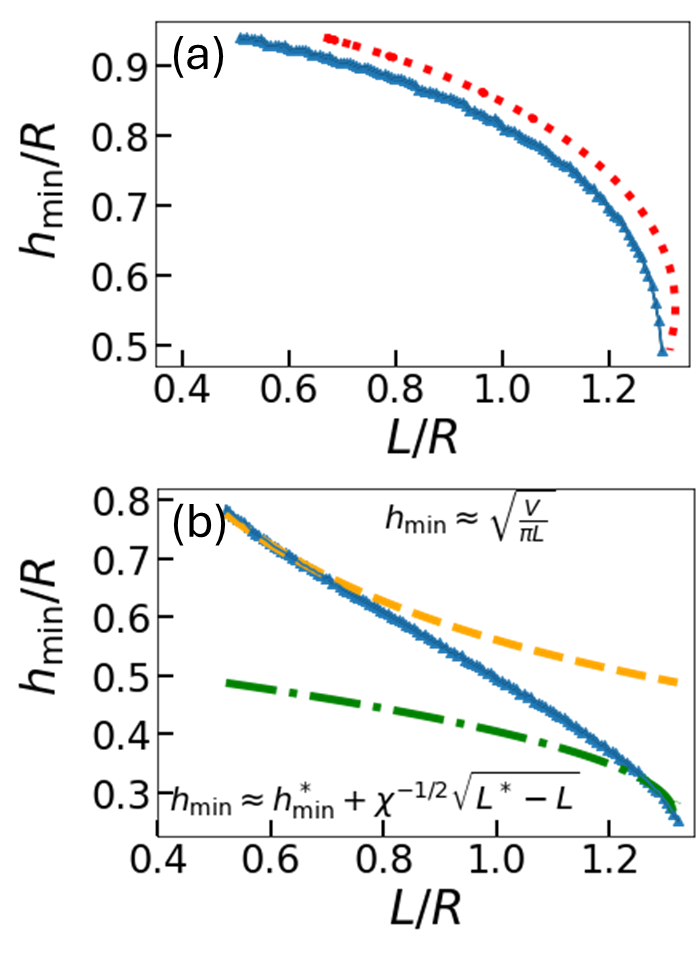
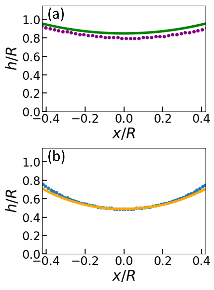
The profile of the film and bubble within the equilibrium regime is governed by . The impact of the volume conservation constraint is evident in the correlation between and , as depicted in Fig. 3(a, b). In comparison to the film, the bubble roughly conserves its air volume when pulled apart, as certified in Appendix C. The surface of the bubble undergoes a transition from convex to concave, whereas a film maintains a convex shape throughout the equilibrium regime. This distinction will be elaborated in the theory section to explain the positive second derivative of observed in bubbles, in contrast to the negative one in films Chen and Steen (1997); Robinson and Steen (2001); Cryer and Steen (1992), as illustrated in Fig. 3(a, b).
III.2 Breakup regime
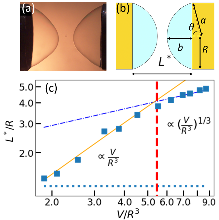
Unlike the flat surfaces observed on rings in the case of films, two spherical bubbles survive the breakage and form on the caps in the case of bubbles. The spherical shape is preferred to minimize surface energy, and the corresponding height , as defined in Fig. 4(a, b), can be calculated accordingly. Simultaneously, the critical length at which irreversible processes are initiated can be theoretically determined by considering the breakdown of the solution and minimizing the potential energy in the equilibrium regime. By comparing these two lengths, we observe that is not only greater than , which explains the necessity for both bubbles to retract and eventually break, but it is also roughly equal to . This observation is validated in Appendix D. Depending on the value of , we anticipate two scenarios for the remaining bubble. Through straightforward calculations in Sec. IV C, it is found that with for and otherwise. This prediction of vs. is effectively confirmed by the results shown in Fig. 4(c).
IV Theoretical derivations
Theoretical analysis of the global geometric features of a collapsing soap film has been performed in detail by Goldstein et al. Goldstein et al. (2021), including the fascinating stages near pinch-off. They showed that the underlying modes are qualitatively the same for mean curvature flow and Euler flow, although the dynamics of their underlying modes are very different. The mechanism that led to pattern formation beyond the critical catenoid was also explained. In contrast, a soap bubble is considerably more difficult to tackle by theoretical means due to the long-ranged mediation of pressure. Notwithstanding, we still managed to derive analytic expressions for some properties primarily in the equilibrium regime after making reasonable approximations.
IV.1 Equilibrium regime
The profile of the bubble in the equilibrium regime is governed by Eq. (4), which cannot be solved analytically. To employ a numerical method such as finite-difference, we differentiate Eq. (4) with respect to to obtain
| (1) |
In the case of a soap film, the Lagrange multiplier should be set to zero. The agreement between the numerical and experimental profiles in the equilibrium regime for soap films and bubbles in Fig. 5(a) indicates that the stretching process can be considered quasi-static and the influence of gravity can be neglected. The small deviations observed in Fig. 5(b) are attributed to the estimation of .
In our experiments, we can stretch both bubbles and films horizontally or vertically. While measures can be taken to reduce sagging and asymmetrical contours caused by gravity by minimizing the volume , it remains uncertain whether the critical behavior at pinch-off will be affected. Theoretical calculations can help us address this concern and provide analytical expressions for quantities of interest, such as , while highlighting the influence of volume conservation. To understand how the parameters affect the contour of the bubble, we begin by minimizing the total energy for the bubble:
| (2) |
where the first integration calculates the surface area, while the second term reinforces the constraint of volume conservation by introducing the Lagrange multiplier . Applying the Euler-Lagrange equation Thornton and Marion (1988) then gives
| (3) |
where the product of surface tension and mean curvature on the right-hand side gives the capillary pressure according to the Young-Laplace equation, and can be identified as the pressure difference of air across the soap membrane. Note that the factor of comes from the projection onto the normal direction of the surface.
Since the integrand of Eq. (2) has no explicit dependence on , it is simpler to appeal to the second form of the Euler-Lagrange equation Thornton and Marion (1988) to obtain
| (4) |
After some approximations and transportation detailed in Section 6.2, we derive
| (5) |
and
| (6) |
where and . By comparing the leading-order term, we obtain
| (7) |
which matches the data in early equilibrium regime for Fig. 3(b).
The derivations from Eq. (4) to Eq. (6) illustrate the crucial role of the Lagrange multiplier and how it mathematically prevents the bubble from adopting the catenoid profile observed in films. These derivations also emphasize the significance of and the subsequent parameter . Without them, the condition would hold, implying that the cylindrical shape is only possible when the two rings are very close together in films. For bubbles, an additional condition stated in Eq. (6) requires the denominator to be comparable to . This renders a finite value of . We can draw insights from the analysis of films. By setting , we plot both sides of Eq. (16) as a function of in Fig. 6(a).
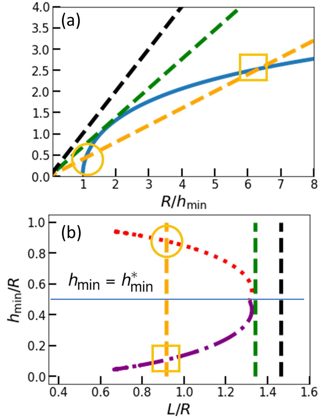
When , there is no intersection, indicating a problem with the starting point for minimizing the surface energy. This aligns with our expectation that films will naturally collapse at large , requiring the minimization of action instead. When , both sides of the equation become tangent. The same is expected for bubbles, meaning that we should differentiate both sides of Eq. (16) with respect to to determine the location of . There are two intersections for , but one of them is unphysical, as explained in Fig. 6(a). When we plot against , the solution should be double-valued until reaches , as shown in Fig. 6(b). Therefore, we can approximate , where is a constant, for values of close to the critical neck radius , beyond which the neck collapses spontaneously. Simple rearrangement gives
| (8) |
Our confidence in Eqs. (7) and (8) is supported by their accurate prediction of an inflection point in Fig. 3(b), which arises from the fact that the curvatures have opposite signs.
IV.2 Breakup regime
The collapse speed of the neck is extremely rapid. As we will discuss later, there are two additional complexities before the final breakage occurs. First, in the pinch-off regime, two necks will form. Second, this is followed by the breaking stage, during which a satellite bubble is created in the middle of these two necks after the hollow, thin tube connecting them transforms into a liquid string. There is no gas leakage during the breaking and relaxation stages, and the volume of the satellite bubble can be neglected. Therefore, should be equal to the combined volume of the two remaining bubbles after breakage. We can directly establish the relationship between and , which can be estimated from Fig. 4(b) where the chord length equals . Using the geometry shown in Fig. 4(b), we can obtain the volume of each partial sphere
| (9) |
where . It is easy to show that the first term dominates when and
| (10) |
while the second term prevails to give
| (11) |
at the other extreme. The predictions of Eqs. (10) and (11) are vindicated by Fig. 4(c).
V Conclusion
This study combines experimental observations with theoretical analysis to elucidate the shape evolution of soap bubbles under the constraint of volume conservation. Since soap films and bubbles are short-lived, previous scientists chose to stretch them vertically because they were easier to burst when placed horizontally. This arrangement rendered the asymmetry in shape due to gravity. In this work, we managed to overcome this technical difficulty by adding guar gum. With the special recipe in Table I, the lifetime can be lengthened by five folds to enable the experimental observations of horizontal stretching, effectively minimizing the effects of gravity.
By contrasting soap bubbles with open films, we demonstrate the critical role of volume conservation in influencing surface tension-driven dynamics. Mainly, the shape of bubbles exhibits a convex-to-concave transition, in contrast to being always convex for films. Theoretically, this is shown to be linked to the Lagrange multiplier associated with the volume conservation. Although not included in this work, preliminary studies of ours showed that the effect of such a constraint persists in influencing the behavior of non-equilibrium fluid systems and underscoring universal behaviors in surface shape. Potential applications involving the volume conservation and breakup of droplets span from the design of microfluidic devices to the study of biological membranes, offering a foundation for exploring broader implications of fluid dynamics and surface tension in physical and applied contexts.
acknowledgment
We are grateful to C. Y. Lai and J. R. Huang for useful discussions and thank P. Yang and J. C. Tsai for the use of high-speed cameras. Financial support from the Ministry of Science and Technology in Taiwan under Grant No. 111-2112-M007-025 and No. 112-2112-M007-015 is acknowledged.
Appendix A Asymmetrical breakup
Occasionally it was observed that the two partial spheres could be of a different size. We believe it was caused by the additional liquid that pends at the bottom of the bubble. When this happens, will become smaller than expected from Eq. (11). The following calculation can verify this anomaly. First, we distinguish the left from the right spheres by appending subscripts and . Second, differentiating the volume
| (12) |
where we have separated into three segments - , the gap, and . Neglecting the small gap, we have . Plugging this into Eq. (12) gives
| (13) |
where the right parenthesis is equivalent to times . The former is positive definite from Eq. (12), and so Eq. (13) requires to share the same sign of if . A short summary of this cute derivation: the bigger the size difference between spheres, the shorter is.
Appendix B Detailed steps of derivation for Section IV.A
After some transpositions, Eq. (4) becomes
| (14) |
Solving this differential equation will enable us to obtain information on the contour :
| (15) |
where . There is no need for an additional constant in Eq. (15) since occurs at .
By implementing the boundary condition that and volume conservation, we get
| (16) |
and
| (17) |
where a change of variable has been performed to render the parameters dimensionless and . By setting , Eq. (16) will revert to depicting a film and give us vs. in agreement with Fig. 3(a). Setting rewrites the right-hand-side of Eq. (16) and (17) as
| (18) |
and
| (19) |
During the stretching of the bubble, there is a certain period where is close to and . Expanding the expression to , the denominator can be simplified as follows:
| (20) | |||
Appendix C Is the volume of bubbles truly conserved?
Young-Laplace equation, , allows us to determine the radius of curvature for the surface by the pressure difference. By using the characteristic length , we estimated that where atm is the initial pressure of air inside the bubble. Treating the air as being ideal, we can employ the equation of state where the particle number and temperature are fixed, and is the Boltzmann constant. Because the pressure is inversely proportional to the volume, the ratio of to is which indicates that is negligible. The small change in volume will become significant when the sum of volume for cap A and tube, roughly 17.0 and 41.5 ml, is times the size of a soap bubble. These two volumes are of the same order in our experiment and therefore we do not need to worry about the extreme case.
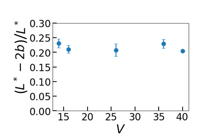
Appendix D Evidence for
According to our theoretical calculation in Section IV.B of the main text, the gap width equals between the tips of remnant soap bubbles after breakup. The relation comes from the experimental result , as shown in Fig. 7.
References
- Leonhard (1744) E. Leonhard, “Methodus inveniendi lineas curvas maximi minimive proprietate gaudentes sive solutio problematis isoperimetrici latissimo sensu accepti,” x 341, 245 (1744).
- Goldstine (1980) H. H. Goldstine, A History of the Calculus of Variations from the 17th through the 19th Century, 1st ed., Studies in the History of Mathematics and Physical Sciences, Vol. 5 (Springer-Verlag New York Inc., New York, NY, 1980) p. 410, published as part of the Springer Book Archive.
- Plateau (1857) J. Plateau, “I. experimental and theoretical researches on the figures of equilibrium of a liquid mass withdrawn from the action of gravity.–third series,” The London, Edinburgh, and Dublin Philosophical Magazine and Journal of Science 14, 1–22 (1857).
- Alexander and Machon (2020) G. P. Alexander and T. Machon, “A björling representation for jacobi fields on minimal surfaces and soap film instabilities,” Proceedings of the Royal Society A: Mathematical, Physical and Engineering Sciences 476, 20190903 (2020), https://royalsocietypublishing.org/doi/pdf/10.1098/rspa.2019.0903 .
- Colding and Minicozzi (2006) T. H. Colding and W. P. Minicozzi, “Shapes of embedded minimal surfaces,” Proceedings of the National Academy of Sciences 103, 11106–11111 (2006).
- Weber, Hoffman, and Wolf (2005) M. Weber, D. Hoffman, and M. Wolf, “An embedded genus-one helicoid,” Proceedings of the National Academy of Sciences 102, 16566–16568 (2005), https://www.pnas.org/doi/pdf/10.1073/pnas.0508008102 .
- Abdolmaleki, Kidmose, and Agarwala (2021) H. Abdolmaleki, P. Kidmose, and S. Agarwala, “Droplet-based techniques for printing of functional inks for flexible physical sensors,” Advanced Materials 33, 2006792 (2021).
- Agrawal, Pandelidis, and Pecht (1987) A. R. Agrawal, I. O. Pandelidis, and M. Pecht, “Injection-molding process control—a review,” Polymer Engineering & Science 27, 1345–1357 (1987).
- Yoon (2001) M. A. Yoon, Yisang McNiven, “Mitochondrial division: New partners in membrane pinching,” Current Biology 11, R67 – R70 (2001).
- Goldstein et al. (2021) R. E. Goldstein, A. I. Pesci, C. Raufaste, and J. D. Shemilt, “Geometry of catenoidal soap film collapse induced by boundary deformation,” Phys. Rev. E 104, 035105 (2021).
- Cheng et al. (2021) Y.-C. Cheng, T.-H. Hsieh, J.-C. Tsai, and T.-M. Hong, “Phase diagram and snap-off transition for twisted party balloons,” Phys. Rev. E 104, 045004 (2021).
- Dussan V (1975) E. B. Dussan V, “Hydrodynamic stability and instability of fluid systems with interfaces,” Archive for Rational Mechanics and Analysis 57, 363 – 379 (1975).
- Lister and Stone (1998) J. R. Lister and H. A. Stone, “Capillary breakup of a viscous thread surrounded by another viscous fluid,” Physics of Fluids 10, 2758–2764 (1998).
- Ting and Keller (1990) L. Ting and J. B. Keller, “Slender jets and thin sheets with surface tension,” SIAM Journal on Applied Mathematics 50, 1533–1546 (1990).
- Peregrine, Shoker, and Symon (1990) D. H. Peregrine, G. Shoker, and A. Symon, “The bifurcation of liquid bridges,” Journal of Fluid Mechanics 212, 25–39 (1990).
- Eggers (1993) J. Eggers, “Universal pinching of 3d axisymmetric free-surface flow,” Phys. Rev. Lett. 71, 3458–3460 (1993).
- Schulkes (1994) R. M. S. M. Schulkes, “The evolution and bifurcation of a pendant drop,” Journal of Fluid Mechanics 278, 83–100 (1994).
- Brenner, Shi, and Nagel (1994) M. P. Brenner, X. D. Shi, and S. R. Nagel, “Iterated instabilities during droplet fission,” Phys. Rev. Lett. 73, 3391–3394 (1994).
- Eggers and Dupont (1994) J. Eggers and T. F. Dupont, “Drop formation in a one-dimensional approximation of the navier–stokes equation,” Journal of Fluid Mechanics 262, 205–221 (1994).
- Shi, Brenner, and Nagel (1994) X. D. Shi, M. P. Brenner, and S. R. Nagel, “A cascade of structure in a drop falling from a faucet,” Science 265, 219–222 (1994).
- Kowalewski (1996) T. Kowalewski, “On the separation of droplets from a liquid jet,” Fluid Dynamics Research 17, 121–145 (1996).
- Zhang and Stone (1997) D. F. Zhang and H. A. Stone, “Drop formation in viscous flows at a vertical capillary tube,” Physics of Fluids 9, 2234–2242 (1997).
- Wilkes, Phillips, and Basaran (1999) E. D. Wilkes, S. D. Phillips, and O. A. Basaran, “Computational and experimental analysis of dynamics of drop formation,” Physics of Fluids 11, 3577–3598 (1999).
- Notz, Chen, and Basaran (2001) P. K. Notz, A. U. Chen, and O. A. Basaran, “Satellite drops: Unexpected dynamics and change of scaling during pinch-off,” Physics of Fluids 13, 549–552 (2001).
- Ambravaneswaran, Wilkes, and Basaran (2002) B. Ambravaneswaran, E. D. Wilkes, and O. A. Basaran, “Drop formation from a capillary tube: Comparison of one-dimensional and two-dimensional analyses and occurrence of satellite drops,” Physics of Fluids 14, 2606–2621 (2002).
- Lee, Lowengrub, and Goodman (2002) H.-G. Lee, J. S. Lowengrub, and J. Goodman, “Modeling pinchoff and reconnection in a Hele-Shaw cell. II. Analysis and simulation in the nonlinear regime,” Physics of Fluids 14, 514–545 (2002).
- Subramani et al. (2006) H. J. Subramani, H. K. Yeoh, R. Suryo, Q. Xu, B. Ambravaneswaran, and O. A. Basaran, “Simplicity and complexity in a dripping faucet,” Physics of Fluids 18, 032106 (2006).
- Xu and Basaran (2007) Q. Xu and O. A. Basaran, “Computational analysis of drop-on-demand drop formation,” Physics of Fluids 19, 102111 (2007).
- Eggers and Villermaux (2008) J. Eggers and E. Villermaux, “Physics of liquid jets,” Reports on Progress in Physics 71, 036601 (2008).
- Huang, Pan, and Josserand (2019) K.-L. Huang, K.-L. Pan, and C. Josserand, “Pinching dynamics and satellite droplet formation in symmetrical droplet collisions,” Phys. Rev. Lett. 123, 234502 (2019).
- Cohen et al. (1999) I. Cohen, M. P. Brenner, J. Eggers, and S. R. Nagel, “Two fluid drop snap-off problem: Experiments and theory,” Phys. Rev. Lett. 83, 1147–1150 (1999).
- Zhang and Lister (1999) W. W. Zhang and J. R. Lister, “Similarity solutions for capillary pinch-off in fluids of differing viscosity,” Phys. Rev. Lett. 83, 1151–1154 (1999).
- Cohen and Nagel (2001) I. Cohen and S. R. Nagel, “Testing for scaling behavior dependence on geometrical and fluid parameters in the two fluid drop snap-off problem,” Physics of Fluids 13, 3533–3541 (2001).
- Sierou and Lister (2003) A. Sierou and J. R. Lister, “Self-similar solutions for viscous capillary pinch-off,” Journal of Fluid Mechanics 497, 381–403 (2003).
- Dinic and Sharma (2019) J. Dinic and V. Sharma, “Computational analysis of self-similar capillary-driven thinning and pinch-off dynamics during dripping using the volume-of-fluid method,” Physics of Fluids 31, 021211 (2019).
- Lagarde, Josserand, and Protière (2018) A. Lagarde, C. Josserand, and S. Protière, “Oscillating path between self-similarities in liquid pinch-off,” Proceedings of the National Academy of Sciences 115, 12371–12376 (2018).
- Burton, Rutledge, and Taborek (2007) J. C. Burton, J. E. Rutledge, and P. Taborek, “Fluid pinch-off in superfluid and normal ,” Phys. Rev. E 75, 036311 (2007).
- Keller (1983) J. B. Keller, “Breaking of liquid films and threads,” The Physics of Fluids 26, 3451–3453 (1983).
- Bergmann et al. (2006) R. Bergmann, D. van der Meer, M. Stijnman, M. Sandtke, A. Prosperetti, and D. Lohse, “Giant bubble pinch-off,” Phys. Rev. Lett. 96, 154505 (2006).
- Villermaux, Marmottant, and Duplat (2004) E. Villermaux, P. Marmottant, and J. Duplat, “Ligament-mediated spray formation,” Phys. Rev. Lett. 92, 074501 (2004).
- Chen and Steen (1997) Y.-J. Chen and P. H. Steen, “Dynamics of inviscid capillary breakup: collapse and pinchoff of a film bridge,” Journal of Fluid Mechanics 341, 245–267 (1997).
- Day, Hinch, and Lister (1998) R. F. Day, E. J. Hinch, and J. R. Lister, “Self-similar capillary pinchoff of an inviscid fluid,” Phys. Rev. Lett. 80, 704–707 (1998).
- Robinson and Steen (2001) N. D. Robinson and P. H. Steen, “Observations of singularity formation during the capillary collapse and bubble pinch-off of a soap film bridge,” Journal of Colloid and Interface Science 241, 448–458 (2001).
- Cryer and Steen (1992) S. A. Cryer and P. H. Steen, “Collapse of the soap-film bridge: quasistatic description,” Journal of Colloid and Interface Science 154, 276–288 (1992).
- Jia et al. (2021) L. L. Jia, S. Pei, R. A. Pelcovits, and T. R. Powers, “Axisymmetric membranes with edges under external force: buckling, minimal surfaces, and tethers,” Soft Matter 17, 7268–7286 (2021).
- Boulogne, Restagno, and Rio (2022) F. Boulogne, F. Restagno, and E. Rio, “Measurement of the temperature decrease in evaporating soap films,” Phys. Rev. Lett. 129, 268001 (2022).
- Frazier, Jiang, and Burton (2020) S. Frazier, X. Jiang, and J. C. Burton, “How to make a giant bubble,” Phys. Rev. Fluids 5, 013304 (2020).
- Pasquet et al. (2022) M. Pasquet, L. Wallon, P.-Y. Fusier, F. Restagno, and E. Rio, “An optimized recipe for making giant bubbles,” The European Physical Journal E 45, 100 (2022).
- Ahmed, Sung, and Kim (2011) D. H. Ahmed, H. J. Sung, and D.-S. Kim, “Simulation of non-newtonian ink transfer between two separating plates for gravure-offset printing,” International Journal of Heat and Fluid Flow 32, 298–307 (2011).
- Slobozhanin and Perales (1993) L. A. Slobozhanin and J. M. Perales, “Stability of liquid bridges between equal disks in an axial gravity field,” Physics of Fluids A: Fluid Dynamics 5, 1305–1314 (1993).
- Galaktionov, Galaktionova, and Tropp (2020) E. V. Galaktionov, N. E. Galaktionova, and E. A. Tropp, “The shape of a vertical liquid bridge between arbitrary convex surfaces in axisymmetric case,” Journal of Physics: Conference Series 1697, 012081 (2020).
- Papageorgiou (1995) D. T. Papageorgiou, “On the breakup of viscous liquid threads,” Physics of Fluids 7, 1529–1544 (1995).
- Zhang, Padgett, and Basaran (1996) X. Zhang, R. S. Padgett, and O. A. Basaran, “Nonlinear deformation and breakup of stretching liquid bridges,” Journal of Fluid Mechanics 329, 207–245 (1996).
- Darhuber, Troian, and Wagner (2001) A. A. Darhuber, S. M. Troian, and S. Wagner, “Physical mechanisms governing pattern fidelity in microscale offset printing,” Journal of Applied Physics 90, 3602–3609 (2001).
- Sack and Pöschel (2017) A. Sack and T. Pöschel, “Dripping faucet in extreme spatial and temporal resolution,” American Journal of Physics 85, 649–654 (2017).
- Thornton and Marion (1988) S. T. Thornton and J. B. Marion, Classical dynamics of particles and systems, 3rd ed. (San Diego : Harcourt Brace Jovanovich, San Diego, 1988) p. 602.