A Real-Time System for Scheduling and
Managing UAV Delivery in Urban
Abstract
As urban logistics demand continues to grow, UAV delivery has become a key solution to improve delivery efficiency, reduce traffic congestion, and lower logistics costs. However, to fully leverage the potential of UAV delivery networks, efficient swarm scheduling and management are crucial. In this paper, we propose a real-time scheduling and management system based on the “Airport-Unloading Station” model, aiming to bridge the gap between high-level scheduling algorithms and low-level execution systems. This system, acting as middleware, accurately translates the requirements from the scheduling layer into specific execution instructions, ensuring that the scheduling algorithms perform effectively in real-world environments. Additionally, we implement three collaborative scheduling schemes involving autonomous ground vehicles (AGVs), unmanned aerial vehicles (UAVs), and ground staff to further optimize overall delivery efficiency. Through extensive experiments, this study demonstrates the rationality and feasibility of the proposed management system, providing practical solution for the commercial application of UAVs delivery in urban.
Code: https://github.com/chengji253/UAVDeliverySystem
Index Terms:
UAV delivery in urban, real-time management system, scheduling scheme.I INTRODUCTION
With the continuous growth of urban logistics demand, using UAVs for delivery has become a key solution to improve delivery efficiency, reduce traffic congestion, and lower logistics costs. An increasing number of companies are deploying UAV delivery networks in cities, driving rapid advancements in this field. A key aspect of enhancing delivery efficiency lies in the effective management and scheduling of multiple UAVs, ensuring seamless collaboration between UAVs and ground staff.
There has been extensive research on improving the efficiency of UAV delivery systems [1], focusing on the following aspects: Firstly, optimizing from the perspective of scheduling strategies [2, 3, 4, 5]. Secondly, reducing flight time and avoiding conflicts from a path planning perspective [6, 7, 8, 9]. Additionally, improving energy efficiency is another critical direction [10, 11, 12, 13]. Finally, efficient use of airspace resources is also an important means to improve efficiency [14, 15, 16]. Some companies, such as Google Wing [17], Flytrex [18], Amazon [19], and Meituan [20], have already made progress in commercialization.
Building on this progress in commercialization, the most commonly applied model in UAV delivery is the “Airport-Unloading Station” model. In cities, dedicated UAV airports are established as distribution centers. UAVs take off from the airport and fly directly to the unloading station to complete the entire delivery process. There are many directions to improve the efficiency of the airport model, including flight path planning, UAV swarm scheduling, and the collaboration between ground staff and UAVs (such as takeoff, cargo loading, and battery replacement). To address this, we need to optimize the entire problem and design a top-level architecture from an operations research perspective, establishing efficient scheduling algorithms to enhance delivery efficiency.
However, applying scheduling algorithms to real-world scenarios still faces numerous challenges. Firstly, many algorithms often overlook the integration with the underlying execution infrastructure, and the problem modeling includes unrealistic simplifications. Additionally, many algorithms are designed for offline use, resulting in long calculation times, which are not suitable for real-time scheduling needs. In practice, we find that the scheduling layer often fails to accurately translate scheduling requirements into specific execution commands. Furthermore, the scheduling layer is unaware of the exact state of the underlying system and does not know whether the scheduling requirements are correctly executed. Therefore, there is an urgent need for a real-time management system that bridges the gap between scheduling algorithms and the execution system, ensuring the smooth implementation of scheduling and transport tasks.
To address these challenges, we propose a real-time scheduling and management system for the “Airport-Unloading Station” model. This system serves as middleware for UAV delivery processes, connecting upper-level scheduling requirements with lower-level execution mechanisms, ensuring that scheduling algorithms can run effectively in real-world environments. Building on this management system, we have also implemented three scheduling solutions for AGVs and UAVs to ensure efficient coordination between AGVs, UAVs, and ground staff, thereby optimizing overall delivery efficiency. The main contributions of this study are as follows:
-
•
We design a scheduling management system tailored to urban delivery demands, achieving efficient and dynamic UAV delivery scheduling.
-
•
Based on this management system, we implement three scheduling schemes for AGVs, UAVs, and ground staff, optimizing the coordination between them.
-
•
We demonstrate the effectiveness of the proposed management system through experiments, offering a practical solution for the commercial application of UAVs delivery in urban.
II related work
Improving the efficiency of UAV delivery systems in urban environments can be achieved through various approaches, which can be broadly categorized as follows:
Firstly, optimizing scheduling algorithms plays a significant role in enhancing overall performance. Sajid et al. [2] proposed a hybrid optimization framework that combines genetic algorithm and simulated annealing algorithm to solve the path planning and scheduling problems. Murray et al. [3] proposed a mathematical model to optimize the cooperative delivery of drones and traditional trucks, and improved the delivery efficiency by optimizing the delivery path and scheduling. Hong et al. [4] a proposed a two-stage optimization method to solve the scheduling problem of drones in urban last-mile delivery and improved task allocation and route planning. Das et al. [5] proposed a scheduling mechanism for synchronized drones and delivery trucks to optimize the multi-objective delivery problem.
Second, path planning is another critical factor in optimizing delivery systems. Yan et al. [6] proposed a service model that performs path planning through an aerial channel network infrastructure and adopts a reactive scheduling method to cope with service failures. Xie et al. [7] proposed an AI-based 4D trajectory management system that can adjust flight paths in real time and solve airspace overload and conflict problems. Pei et al. [8] proposed an exact algorithm to optimize drone flight routes in urban on-demand delivery, taking into account time windows and spatial conflicts. Oliveira et al. [9] explores the collision avoidance problem of UAVs in an urban environment and evaluates different automatic geometric collision avoidance methods.
Moreover, energy efficiency is a crucial aspect for optimizing UAV delivery systems. Dorling et al.[10] discussed the delivery routing problem of drones cooperating with trucks and proposed an optimization model to consider energy consumption and battery consumption. Park et al.[11] proposed a scheduling algorithm based on reinforcement learning to optimize the collaborative delivery efficiency of drones and take energy consumption into consideration. Cho et al.[12] proposed a coordinated delivery strategy of hybrid trucks and drones to optimize energy efficiency and delivery efficiency. Huang et al.[13] studied the method of replacing batteries through drone stations to solve the drone endurance problem and improve the last mile delivery efficiency.
Lastly, airspace resource management is essential for scaling up UAV delivery systems. Li et al.[14] proposed a drone traffic management framework covering path planning, conflict detection, airspace resource allocation, etc., aiming to optimize package delivery at low altitudes in cities. Pang et al.[15] introduces a chance-constrained urban air traffic flow management optimization model that addresses uncertainties such as flight delays and trajectory deviations. Safadi et al.[16] designed a model-based control strategy to regulate demand and supply in a low-altitude urban transportation system and ensure a balanced airspace.
III Preliminaries
Our research is based on the “Airport-Unloading Station” model, where a dedicated UAV delivery airport is established in the city. All UAVs take off from the airport, carrying goods to the nearest unloading station for delivery. After completing the drop-off, the UAVs return to the airport for reloading and then proceed to the next round of delivery. When a customer submits an order on the platform, nearby merchants send the goods to the airport. The staff are responsible for loading the goods onto the UAVs. The UAVs then follow a predetermined flight route to the nearest unloading station for delivery. After the delivery is completed, the UAVs return to the airport and prepare for the next delivery task.
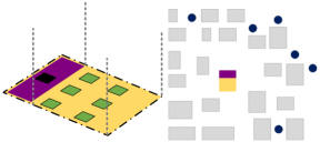
Fig.1 shows the layout of the airport, where the purple area represents the Ground Work (GW) area. The black section within the GW area is the workbench, where staff carry out tasks such as cargo loading, battery replacement, UAV recovery. The orange area is the Aviation Work (AW) area, where only UAVs are allowed to take off and land. The green area represents the AGV, which is responsible for transporting UAVs between the GW area and the AW area. After a UAV lands, the AGV transports it to the GW area, where the staff completes the necessary tasks, and then the AGV takes the UAV back to the AW area for the next takeoff.
To ensure the safety of ground staff, the GW area is separated from the AW area. AGVs are used to transport UAVs between the two areas to avoid any risks associated with UAV takeoff and landing. We define the set of UAVs as , where the index is . The set of AGVs is defined as , with the index . The black circles in Fig. 1 represent the unloading stations in the urban. Once the UAVs arrive at the unloading stations, the goods are unloaded, and customers can pick up their orders. The set of unloading stations is defined as , with each unloading station indexed by . Each unloading station has a forward route and a return route. The forward route to the unloading station is represented by , and the return route is represented by .
IV Management system
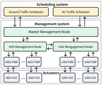
In this section, we discuss the details of the management system. The management system serves as middleware, bridging the underlying execution structure and the upper-level scheduling layer. Fig.2 illustrates the framework of our management system. As shown in the figure, our management system mainly consists of three management nodes: the Master Management Node, the AGV Management Node, and the UAV Management Node (highlighted in green). These three nodes run as independent processes in real time and collaborate through information exchange. Below, we will first introduce the specific functions of each management node. Then we introduce the details of the UAV finite state machine and the AGV finite state machine.
IV-A Management nodes
AGV Management Node: The AGV management node is responsible for managing and controlling the states of the AGVs. It employs a combined approach of multithreading and Finite State Machines (FSMs). Each behavior of AGVs is governed by an independent FSM, which defines the various tasks and operational processes through state transition rules. The FSMs run independently in real-time, accepting commands and continuously updating their states, ensuring that the AGVs perform tasks according to predefined behaviors. During the system initialization phase, the management node launches an independent thread for each AGV, within which the corresponding FSM operates and updates its state at a fixed frequency, guaranteeing real-time responsiveness and precise control of the system. The AGV management node itself also updates its state and receives instructions at a fixed frequency. Upon receiving commands from the central management node, the management node forwards them to the appropriate FSM thread to control the individual AGV. Simultaneously, the AGV management node publishes the state information of all AGVs in real-time, ensuring that other system nodes can access the latest task progress and status changes. The state of each AGV is categorized based on the current task type and operational progress and is transmitted using a dedicated message format.
UAV Management Node: The UAV management node is responsible for managing and controlling the states of the UAVs. Similar to the AGV management node, it utilizes a multithreading approach combined with Finite State Machines (FSMs). Each behavior of UAVs is controlled by an independent FSM, which updates its state in real-time based on predefined rules and commands. The UAV management node operates at a fixed frequency, ensuring real-time responsiveness. It receives commands from the central management node, forwards them to the corresponding UAV FSM, and publishes the state information of all UAVs for system-wide visibility. The state of each UAV is categorized based on its current task and progress and is transmitted using a standardized message format.
Master Management Node: The master management node serves as the central hub connecting the scheduling layer with the management layer. It subscribes to real-time data from both the UAV and AGV management nodes, processing and storing this information. This node provides the scheduling module with access to up-to-date status information for all UAVs and AGVs, enabling it to develop optimal scheduling strategies. Upon receiving scheduling commands, the master management node distributes them to the relevant UAV or AGV management nodes, which then forward the commands to the appropriate FSM for execution.
We opted for a distributed node management approach, where the management of UAVs and AGVs is handled independently, with each UAV or AGV assigned a dedicated sub-thread. This design offers the following benefits: (1) Fault isolation and tolerance: If an UAV or AGV encounters an issue, it does not impact the operation of other vehicles or their threads. Each management of vehicles is isolated, ensuring that failures are contained and do not disrupt the overall system. (2) Real-time monitoring and scheduling: The master management node can continuously monitor the status of each UAV and AGV, enabling dynamic adjustments to task allocation and scheduling strategies. This ensures the system remains flexible and efficient, adapting to changing conditions in real time. (3) Scalability: As the system grows, new UAVs or AGVs can be easily added by allocating a new management sub-thread. This scalable design avoids the need for significant modifications to the system architecture, facilitating easy expansion.
IV-B UAV Finite state machine
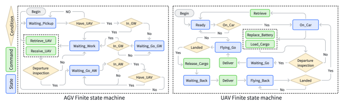
Fig.3 shows the state machine flow chart of the UAV. The blue boxes represent states, green boxes represent commands, and yellow boxes represent conditional checks. The state machine includes six working states, five commands and three conditional judgments, which are described as follows:
UAV working states: (1) Ready: The UAV is in its initial idle state, remaining stationary at the airport and awaiting loading. (2) On_Car: The UAV transitions to this state when mounted on the AGV for transportation. (3) Waitting_Go: This state represents the UAV waiting for a flight command to the delivery point after loading is completed in the GW area. (4) Flying_Go: The UAV enters this state upon takeoff and while flying toward the unloading station. (5) Waitting_Back: After completing the unloading process at the destination, the UAV transitions to this state to await a return command. (6) Flying_Back:The UAV transitions to this state during its return flight to the airport.
UAV commands: (1) Delivery: Initiates the takeoff and flight toward the designated delivery point. (2) Release_Cargo: Permits cargo unloading at the delivery point. This command is only valid when the UAV is landed. (3) Load_Cargo: Allows cargo to be loaded onto the UAV. (4) Replace_Battery: Triggers a battery replacement process. (5) Retrieve: Recovers the UAV for maintenance or storage.
UAV conditional checks: (1) Landed: Verifies whether the UAV has landed safely. (2) On_Car: Confirms if the UAV is mounted on the AGV. (3) Departure_inspection: Ensures all departure requirements are met, including cargo loading and sufficient battery levels.
IV-C AGV Finite state machine
The AGV is responsible for transporting UAV between the AW area and the GW area, handling UAV takeoff and landing operations, as well as loading and unloading tasks. To fulfill these responsibilities, we have designed four working states for the AGV along with corresponding task commands.
AGV Working States: (1) Waitting_Go_GW: The AGV transitions to this state after receiving a landed UAV in the AW area, indicating it will soon transport the UAV to the GW area. (2) Waitting_Pickup: This state represents the AGV waiting in the AW area for a UAV to land, with no UAV currently on board. (3) Waitting_Working: Once the AGV arrives at the GW area with a UAV onboard, it enters this state and waits for ground personnel to perform tasks such as cargo loading or battery replacement. (4) Waitting_Go_AW: After ground personnel complete their tasks, the AGV transitions to this state, ready to transport the UAV back to the AW area.
AGV Commands: (1) Receive_UAV: Instructs the AGV to load the UAV after arriving at the GW area. (2) Retrieve_UAV: Commands the AGV to unload the UAV, setting it to an idle state.
AGV Conditional Checks: (1) Have_UAV : Verifies whether the AGV currently has a UAV on board. (2) In_GW : Checks whether the AGV is in GW area. (3) In_AW : Checks whether the AGV is in the AW area. (4) Departure_inspection: Ensures all departure requirements are met, such as verifying the UAV is loaded and ready. This serves as an additional layer of safety, complementing the departure check of UAV.
IV-D State Transition Process
After introducing the details of the two finite state machines, we will describe a complete delivery process with states and commands information. The process begins with the UAV in the Ready state and the AGV in the Waitting_Pickup state. The AGV begins moving toward the GW area and receives the Receive_UAV command, which triggers the placement of the UAV onto the AGV. Consequently, the UAV transitions to the On_Car state, and the AGV changes to the Waitting_Working state. Subsequently, the UAV receive the Load_Cargo command, at which point the operator begins loading the cargo. Once the Departure_inspection is completed, the state of UAV transitions to Waitting_Go, and the state of AGV changes to Waitting_Go_AW. The AGV, carrying the UAV, proceeds toward the AW area. Upon reaching the takeoff point, the AGV issues the Delivery command, prompting the UAV to take off and fly toward the unloading station. Upon reaching the unloading station, the AGV sends the unload command, completing the unloading process, and the state of UAV transitions to Waitting_Back. Following this, the AGV sends the Delivery command to the UAV, which then takes off and follows the return flight path. Upon returning, the UAV lands back onto the AGV at the airport. At this point, the state of UAV transitions to On_Car, and the state of AGV changes to Waitting_Go_GW. The AGV then transports the UAV back to the GW area for reloading, and the cycle repeats. This process constitutes a complete delivery cycle.
These commands and states in finite state machines can better help scheduling algorithms express their scheduling requirements, thereby helping tasks to be completed better.
V Scheduling system
In the aviation field, the takeoff process of commercial aircraft typically involves multiple steps: obtaining departure clearance, contacting ground control for taxi clearance, communicating with the tower for takeoff clearance, and coordinating with departure and area control after takeoff. These operations are managed by the airport tower staff.
Our scheduling system draws inspiration from this air traffic control model, but with a key difference: it operates autonomously, without the need for human intervention. The system consists of two independent schedulers—one for ground traffic and another for air traffic—that work together to manage UAV delivery tasks. The scheduling system is supported by the management system introduced in the previous section, which provides the underlying support for various scheduling schemes. The following section will provide a detailed introduction to these two schedulers.
V-A Ground traffic scheduler
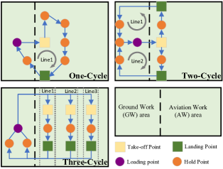
The ground traffic scheduler is responsible for scheduling AGVs to transport UAVs between the AW and GW areas. Fig. 4 illustrates the ground traffic scheduling process, which includes three distinct schemes: One-Cycle, Two-Cycle, and Three-Cycle. Each scheme involves key operational nodes such as the Take-off Point (yellow), Hold Point (orange), Loading Point (purple), and Landing Point (green).
In the One-Cycle scheme, a single loop is used, with one takeoff point and one landing point. Six AGVs operate on this loop. Once an AGV completes loading a UAV at the Loading Point, it transports the UAV to the Takeoff Point. The UAV is permitted to take off only after reaching this point. The AGV then moves sequentially through the Hold Points, advancing to the next as each preceding point becomes available. Finally, the AGV arrives at the Landing Point to retrieve a returning UAV. After landing, the AGV transports the UAV to the GW area for subsequent operations.
The Two-Cycle scheme divides operations into two loops with one shared takeoff point and two landing points. Three AGVs are assigned to each loop. Similar to the One-Cycle scheme, after loading the UAV, the AGV delivers it to the Takeoff Point. Once the UAV takes off, the AGV proceeds to its designated Landing Point to collect a returning UAV.
In the Three-Cycle scheme, three independent loops are implemented, each with its own takeoff point and landing point. Two AGVs are assigned to each loop. These AGVs operate continuously, transporting UAVs between the AW and GW areas within their respective loops.
All three schemes adopt a process resembling an assembly line. This ensures seamless scheduling by minimizing idle time. For example, while one AGV transports a UAV to the GW area, another AGV can wait at the Landing Point for an arriving UAV. Once an AGV exits the GW area, it moves to a Hold Point, continuing the cycle. This approach ensures that an AGV is consistently available at the Landing Point, reducing delays caused by multiple UAVs landing simultaneously without sufficient ground vehicles for retrieval. This cyclic scheduling strategy optimizes ground vehicle utilization and enhances coordination between UAVs and AGVs, ensuring efficient and reliable UAV delivery operations.
V-B Air traffic scheduler
The air traffic scheduler is mainly responsible for determining whether a UAV can take off and sending the corresponding flight route instructions to the UAV.
When an AGV transports a UAV to the takeoff point, the UAV will send a takeoff request to the scheduler. Then it determines whether the UAV can take off and, if allowed, sends the corresponding flight route . Similarly, when the UAV reaches the unloading station, it will request permission from the scheduler to return. After making the judgment, the scheduler sends the return route and specifies the landing point.
To determine whether a UAV can take off or return, several factors are considered. When the UAV arrives at the take-off point, it sends a take-off request to the scheduler. Define the time moment when the take-off request is sent by the th UAV as . Afterward, the scheduler calculates the flight time from the airport to the unloading station based on the destination and the flight route . The time the UAV reaches the unloading station can then be calculated as:
| (1) |
If there are already some UAVs on the route to the unloading station, the set of UAVs heading towards unloading station is denoted as . For the UAV , the time it reaches the unloading station is . At this point, the UAV making the takeoff request must meet the following condition:
| (2) |
where is a predetermined time buffer. It means that for the UAV making a takeoff request and another UAV already on its way to the same unloading station , the time difference between their arrivals must be higher than . Of course, if no other UAVs are heading to the unloading station, the UAV can take off directly.
For the returning UAV , the time point when it sends a return request is . The flight time from the unloading station to the airport is . Therefore, the time point when the aircraft lands at the airport is:
| (3) |
After calculating the landing time point, the scheduling system will select an appropriate line for landing. For each line, we define the time at which the th AGV reaches the landing point as . This represents the time point at which the current AGV arrives at the landing point, and this time must satisfy the constraint:
| (4) |
This constraint means that the AGV must arrive at the landing point and wait before the UAV returns. When calculating , the current state of the AGV must be considered. If the AGV is already waiting at the landing point, the UAV can return directly, as the constraint will be satisfied. If the AGV has just departed from the GW area, the arrival time must be estimated based on the current time, the travel time, and the launch time of UAV. If the AGV has just picked up the UAV and has not yet reached the GW area, the estimated time will be longer. This calculation will be based on the current time, the travel time to the GW, the loading and battery swapping time, and the time required for the AGV to travel from the GW to the landing point.
Each line has some AGVs available for selection. If the first AGV has already been reserved, the second AGV can be chosen, and its landing time can also be estimated. If multiple lines satisfy the constraint, the scheduling system will select the line with the fewest reservations for landing. Each time a UAV sends a return request, the scheduler will iterate through all the lines to determine which lines satisfy the constraint. Once a suitable line is found, the scheduler will assign the landing point and send the flight path instructions to ensure the safe return. By using real-time calculations and a reservation mechanism, the scheduling system can effectively coordinate the UAV and AGV schedules, improving the efficiency and safety of the UAV return process.
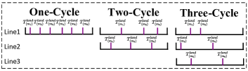
Fig.6 shows the time distribution of AGV arrivals at the landing points for the three schemes. The horizontal axis represents time, with denoting the time at which an AGV reaches the landing point. In the One-Cycle scheme, all AGVs need to go to the same landing point. Although this leads to congestion, once one vehicle reaches the landing point, subsequent vehicles can follow closely behind, resulting in shorter intervals between arrivals. In contrast, the Two-Cycle and Three-Cycle schemes increase the number of landing points, which reduces the number of available vehicles for each line. This causes longer intervals between the arrival times at each landing point. However, their advantage lies in providing more landing point options for UAVs, and there is no required time gap between different landing points.
Remark: Regarding the flight routes and in the section of air traffic scheduler, we have not delved into this aspect, but have assumed that specific flight routes are already available. In actual urban delivery operations, efficiently utilizing urban airspace, planning appropriate flight routes between each airport and unloading station, and ensuring safe operation of UAVs to avoid collisions is a critical and complex issue. Since this problem is not the core focus of our research, we have simplified the discussion by assuming that the flight paths have already been pre-planned and are available for use.
VI Experiments
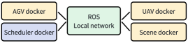
This section presents the experimental analysis of our system. Our experiments were conducted on a PC with an Intel Core i7-12700 CPU and 32GB of RAM. Fig.7 illustrates the experimental setup framework. The framework consists of four Docker containers, each responsible for a specific functional module: (1) AGV Docker: Simulates the low-level control of the AGVs. Each AGV operates an independent real-time controller within its container to carry out tasks. (2) UAV Docker: Handles the low-level control of the UAVs. Within this container, each UAV uses a flight controller similar to PX4[21], with trajectory control managed by model predictive control. (3) Scenario Docker: Coordinates the entire competition scenario, including collision detection between UAVs and urban buildings, as well as the interaction between UAVs, airports, and unloading stations. (4) Scheduling Docker: Runs the management system we developed for scheduling and coordinating tasks. These containers are interconnected via custom user-defined network of Docker, each assigned a fixed IP address. Communication between containers is facilitated by Robot Operating System (ROS), which supports task publishing and subscribing, state information transmission, and overall system coordination. Real-time state data from all AGV and UAV controllers can be accessed via ROS topics, while task instructions from the scheduling system are sent to the respective controllers for execution. By separating the UAV and AGV controllers into distinct containers, we more closely simulate real-world operational environments.
The experiment adopts the following parameter settings: The loading cargo time is 10s. The battery replacement time is 10s. The unloading cargo time is 3s. The minimum distance between UAVs is 5 meters, and the maximum flight speed is 10 m/s. For AGVs, the minimum distance is 3 meters, and the maximum movement speed is 1.5 m/s. The number of AGVs is 6. The number of unloading stations is 6. The length and width of the airport are meters. The frequency of the master management node, AGV management node and UAV management node are 2Hz, 2Hz, 2Hz respectively. The frequency of the AGV FSM and UAV FSM are both 10Hz.
In terms of goods orders, we generated a delivery order list in advance. Each order has four time attributes: (1) OrderT: The time when the customer places the order. (2) FinishT: The time when the order is successfully delivered. (3) BetterT: The ideal delivery time, typically based on customer expectations or system optimization. (4) TimeOut: The maximum allowable delivery time; if exceeded, the order is considered overdue. We will give a score based on the time when the UAV delivers the goods. The scoring rules for the system are governed by the following piecewise function:
| (5) |
If the FinishT falls between OrderT and BetterT, the score is a fixed value of 100. If the FinishT falls between BetterT and TimeOut, the score is calculated based on the Equ.(5), where earlier deliveries earn higher scores. If the FinishT exceeds TimeOut, the score is negative, and the later the delivery, the higher the penalty.
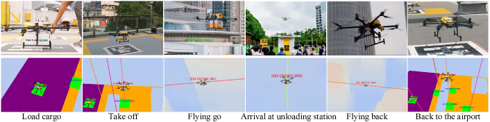
In the experiment, we tested the impact of varying the number of UAVs (4, 6, 8, 10, 12, 14, 16) on the performance of system. For each number, the system was run for one hour, recording the number of deliveries and scores to evaluate system performance. Fig.5 shows the scene of the UAV delivery. We can see a demonstration of the cargo loading, taking off, departing, arriving at the unloading station, returning and finally landing at the airport. For a more detailed demonstration, please refer to our supplementary video.
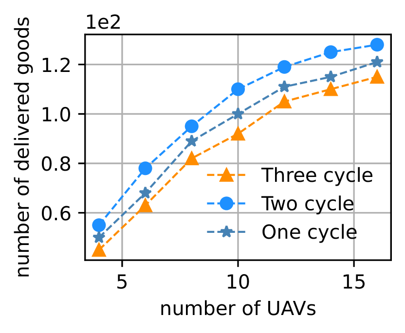
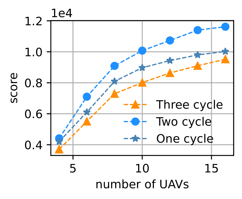
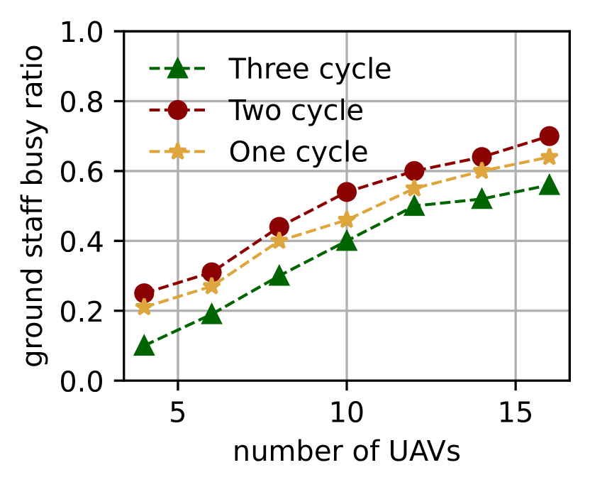
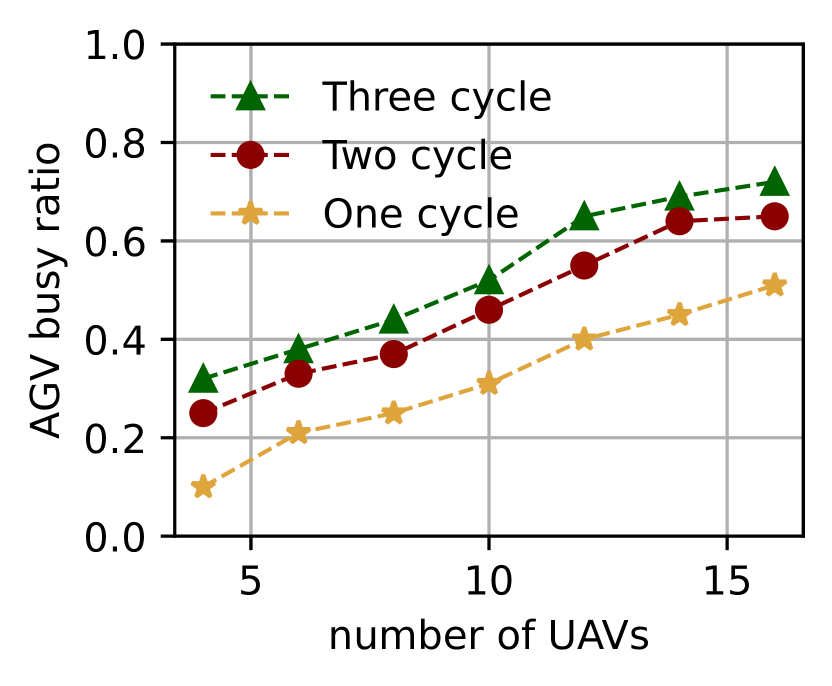
Fig.8 shows the number of goods delivered and the scores obtained after an one-hour experiment using three different scheduling schemes with different numbers of drones. It can be observed that: (1) As the number of UAVs increases, the number of deliveries and scores of the three scheduling schemes will increase. The Two-Cycle received the highest score, followed by the One-Cycle, and the Three-Cycle least. (2) Each time the number of UAVs increases, the percentage of increase in the score will gradually decrease. This shows that the increase in UAVs will improve the efficiency of transportation, but the efficiency improvement has an upper limit. (3) The average delivery score is around 80 points, which means that many orders cannot be delivered before BetterT.
We define the AGV as being in a “free” state when it is idle and awaiting instructions, while all other states are considered “busy” states. Based on this, we recorded the time proportions spent in the “busy” and “free” states over the course of an hour. Similarly, we also recorded the time proportions of ground staff spent performing tasks such as loading, battery replacement, and being in an idle state within an hour. Fig.9 shows the AGV and ground staff busy ratios using three different scheduling schemes with respect to the number of UAVs in one hour. It can be observed that: (1) As the number of UAVs increases, both the ground staff busy ratio and the AGV busy ratio will increase. The addition of UAVs could keep AGVs and ground staff even busier. (2) The Two-Cycle has the highest ground staff busy ratio, but the AGV busy ratio is the second. (3) The Three-Cycle has the lowest ground staff busy ratio, but the AGV busy ratio is the highest. This is because there are three lines in the Three-Cycle, and each AGV needs to spend a lot of time on the road to complete the cycle of line task, but it does not effectively increase the busy ratio of ground staff. The Two-Cycle only costs the second AGV busy ratio, but obtains the highest ground utilization ratio.
From Fig.8 and Fig.9 combined, we find some interesting conclusions: (1) The ranking of ground staff busy ratios is consistent with the ranking of delivery scores. This is because a higher ground utilization rate indicates more cargo is loaded, which brings more scores. (2) The Two-Cycle, at the cost of relatively small AGV usage, achieved the highest score, which shows that the Two-Cycle is the most efficient scheme among the three schemes. (3) The AGV in the Three-Cycle spends too much time on the road, which reduces the efficiency of the system. (4) The AGV busy ratio of the One-Cycle is too low, which indicates that many AGVs waste too much time in waiting state. This is related to the One-Cycle setting, which has only one landing point and take-off point. All AGVs are on this cycle, and only after the AGV at the landing point leaves can the AGV at the hold point enter. In comparison, the Three-Cycle has three landing points. Although the AGV does not need to wait, the time on the road is extended. Therefore, there is room for improvement.
An efficient scheduling scheme requires a balance between AGV utilization and ground resource utilization, optimizing the use of each vehicle while coordinating seamlessly with ground staff. This requires careful design of take-off points, landing points, and waiting areas, as well as strategic route planning. Additionally, the precise coordination of UAV landing times with ground operations is essential to ensure smooth and efficient overall operation. There are only three schemes for scheduling in our experiments, but we believe there will be better schemes.
VII Conclusion
This paper presents a real-time scheduling and management system for urban UAV delivery, effectively bridging the gap between high-level scheduling algorithms and low-level execution systems. Through three collaborative scheduling schemes, the system optimizes the coordination of UAVs, AGVs, and ground staff, improving delivery efficiency. Experimental results validate the rationality and feasibility of our system in urban logistics scenarios.
VIII Acknowledgments
We would like to thank Meituan Academy of Robotics Shenzhen for supporting this research.
References
- [1] J. Pasha, Z. Elmi, S. Purkayastha, A. M. Fathollahi-Fard, Y.-E. Ge, Y.-Y. Lau, and M. A. Dulebenets, “The drone scheduling problem: A systematic state-of-the-art review,” IEEE Transactions on Intelligent Transportation Systems, vol. 23, no. 9, pp. 14 224–14 247, 2022.
- [2] M. Sajid, H. Mittal, S. Pare, and M. Prasad, “Routing and scheduling optimization for uav assisted delivery system: A hybrid approach,” Applied Soft Computing, vol. 126, p. 109225, 2022. [Online]. Available: https://www.sciencedirect.com/science/article/pii/S1568494622004501
- [3] C. C. Murray and A. G. Chu, “The flying sidekick traveling salesman problem: Optimization of drone-assisted parcel delivery,” Transportation Research Part C: Emerging Technologies, vol. 54, pp. 86–109, 2015.
- [4] F. Hong, G. Wu, Q. Luo, H. Liu, X. Fang, and W. Pedrycz, “Logistics in the sky: A two-phase optimization approach for the drone package pickup and delivery system,” IEEE Transactions on Intelligent Transportation Systems, vol. 24, no. 9, pp. 9175–9190, 2023.
- [5] D. N. Das, R. Sewani, J. Wang, and M. K. Tiwari, “Synchronized truck and drone routing in package delivery logistics,” IEEE Transactions on Intelligent Transportation Systems, vol. 22, no. 9, pp. 5772–5782, 2020.
- [6] S. Yan, C.-S. Sun, and Y.-H. Chen, “Optimal routing and scheduling of unmanned aerial vehicles for delivery services,” Transportation Letters, vol. 16, no. 7, pp. 764–775, 2024.
- [7] Y. Xie, A. Gardi, M. Liang, and R. Sabatini, “Hybrid ai-based 4d trajectory management system for dense low altitude operations and urban air mobility,” Aerospace Science and Technology, vol. 153, p. 109422, 2024.
- [8] Z. Pei, T. Fang, K. Weng, and W. Yi, “Urban on-demand delivery via autonomous aerial mobility: Formulation and exact algorithm,” IEEE Transactions on Automation Science and Engineering, vol. 20, no. 3, pp. 1675–1689, 2022.
- [9] F. M. de Oliveira, L. F. Bittencourt, R. A. Bianchi, and C. A. Kamienski, “Drones in the big city: Autonomous collision avoidance for aerial delivery services,” IEEE Transactions on Intelligent Transportation Systems, 2023.
- [10] K. Dorling, J. Heinrichs, G. G. Messier, and S. Magierowski, “Vehicle routing problems for drone delivery,” IEEE Transactions on Systems, Man, and Cybernetics: Systems, vol. 47, no. 1, pp. 70–85, 2016.
- [11] S. Park, C. Park, and J. Kim, “Learning-based cooperative mobility control for autonomous drone-delivery,” IEEE Transactions on Vehicular Technology, 2023.
- [12] Y. H. Cho, D. Baek, Y. Chen, M. J. Jung, S. Vinco, E. Macii, and M. Poncino, “Multi-criteria coordinated electric vehicle-drone hybrid delivery service planning,” IEEE Transactions on Vehicular Technology, vol. 72, no. 5, pp. 5892–5905, 2022.
- [13] C. Huang, Z. Ming, and H. Huang, “Drone stations-aided beyond-battery-lifetime flight planning for parcel delivery,” IEEE Transactions on Automation Science and Engineering, vol. 20, no. 4, pp. 2294–2304, 2022.
- [14] A. Li, M. Hansen, and B. Zou, “Traffic management and resource allocation for uav-based parcel delivery in low-altitude urban space,” Transportation Research Part C: Emerging Technologies, vol. 143, p. 103808, 2022.
- [15] B. Pang, K. H. Low, and V. N. Duong, “Chance-constrained uam traffic flow optimization with fast disruption recovery under uncertain waypoint occupancy time,” Transportation Research Part C: Emerging Technologies, vol. 161, p. 104547, 2024.
- [16] Y. Safadi, N. Geroliminis, and J. Haddad, “Integrated departure and boundary control for low-altitude air city transport systems,” Transportation Research Part B: Methodological, vol. 189, p. 103020, 2024.
- [17] Wing, “Wing - drone delivery,” 2024, accessed: 2024-12-05. [Online]. Available: https://wing.com/
- [18] Flytrex, “Flytrex - drone delivery,” 2024, accessed: 2024-12-05. [Online]. Available: https://www.flytrex.com/
- [19] Amazon, “Amazon’s drone delivery is now delivering to customers in arizona,” 2024, accessed: 2024-12-05. [Online]. Available: https://www.aboutamazon.com/news/transportation/amazon-drone-delivery-arizona
- [20] Meituan, “Meituan technology,” 2024, accessed: 2024-12-05. [Online]. Available: https://www.meituan.com/technology
- [21] “Px4 autopilot: Open source drone control software,” https://px4.io/, 2011–2024, accessed: 2024-12-16.