Orthogonal Geometry of Magneto-Optical Kerr Effect Enabled by Magnetization Multipole of Berry Curvature
Abstract
The Magneto-Optical Kerr Effect (MOKE) is a fundamental tool in magnetometry, pivotal for advancing research in optics, magnetism, and spintronics as a direct probe of magnetization. Traditional MOKE measurements primarily detect the magnetization components parallel to the Poynting vector, which can only access the magnitude but not the direction of the orthogonal component. In this study, we introduce an orthogonal MOKE geometry in which the Kerr signal detects both the magnitude and direction of the magnetization component perpendicular to the Poynting vector. We demonstrate the broad applicability of this orthogonal geometry through the MOKE measurements in cubic ferromagnets and van der Waals ferromagnet. We theoretically show that the orthogonal MOKE geometry is enabled by the multipolar structure of Berry curvature in the magnetization space, which generally induces a Voigt vector orthogonal to the magnetization, thereby accounting for the unique magnetization angle dependence distinct from conventional MOKE. The establishment of the orthogonal MOKE geometry not only introduces a new paradigm for magneto-optical measurements but also provides a framework for exploring the magnetization multipoles of Berry curvature across the electromagnetic spectrum.
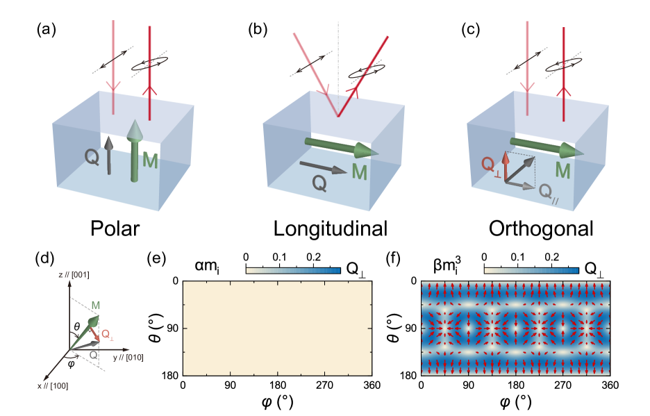
The Magneto-optical Kerr Effect (MOKE) is a vital technique for magnetization sensing, with extensive applications in both research and industry [?,?,?]. Traditionally, magnetization-odd Kerr rotation or ellipticity of light can be observed from ferromagnets via two MOKE geometries: polar MOKE and longitudinal MOKE, as illustrated in Fig. 1a and 1b [?,?,?,?]. The Voigt vector , which describes the Kerr rotation and ellipticity, is commonly assumed parallel to the magnetization [?,?,?]. The alignment between the Voigt vector and the magnetization dictates that the MOKE can only detect the magnetization component parallel to the Poynting vector as in the longitudinal and polar geometry of MOKE [?]. This situation mirrors the collinear relationship between magnetization and Berry curvature in the anomalous Hall effect, positioning the MOKE as the optical analogue of the Hall effect [?,?,?]. Consequently, the magnetization orthogonal to the light has generally been considered beyond the access of the MOKE. Although rare exceptions have been observed in crystalline samples with vicinal surfaces [?,?], the required low symmetry can be rarely satisfied in most ferromagnets, precluding the vicinal interface sensitive MOKE from being accepted as a general MOKE geometry.
The recent observation of the in-plane anomalous Hall effect in ferromagnets suggests that an out-of-plane Berry curvature can be induced by an in-plane magnetization [?,?]. This unconventional geometry can be comprehended through the multipolar structure of Berry curvature in magnetization space, which was proposed as an analogy to Berry curvature multipoles in momentum space [?,?,?,?]. Critically, this out-of-plane Berry curvature under in-plane magnetization also induces an out-of-plane component [?,?], which challenges the assumption in traditional MOKE analysis and should enable the detection of the magnetization component orthogonal to the Poynting vector. Specifically, the out-of-plane can generate a magnetization-odd MOKE signal in light reflected normally off a ferromagnet with in-plane magnetization as illustrated in Fig. 1c, thereby realizing the orthogonal MOKE geometry. This mechanism is also valid in ferromagnetic insulators, where can remain finite at optical frequencies even in the absence of conduction electrons. Crucially, if the Voigt vector indeed reflects the multipolar structure of Berry curvature in magnetization space, which is argued by our theory to be ubiquitously present in ferromagnets [?], the orthogonal MOKE geometry should not be limited to specific systems. Instead, it may represent a general MOKE geometry applicable across a wide range of ferromagnets, a prospect yet to be fully explored.
In this work, we demonstrate the orthogonal MOKE geometry both in conventional cubic ferromagnets and van der Waals ferromagnet, representing the majority of ferromagnetic materials studied in magneto-optics, thereby verifying the broad applicability. Before showing the experimental results, we first use the ferromagnet with cubic lattice as an example to derive the relation between the magnetization multipole of Berry curvature and a Voigt vector orthogonal to magnetization. Following the theoretical work [?], we apply the multipolar expansion to in magnetization space, which can be simplified in the cubic lattice as follows:
| (1) |
considering the symmetry operations of cubic lattice. In this formula, mainly comes from the dipole and the first term reproduces the familiar linear relation between and , while is dominated by the octupole and induces the leading-order nonlinearity between and . denotes the unit vector of in the cubic lattice coordinates. A detailed discussion on the multipolar expansion and symmetry analysis is included in the section I of supplementary material. To demonstrate the essential role of the multipole for the misalignment between and , which directly enables the orthogonal MOKE geometry, we compare the component of perpendicular to contributed by the and terms as examples, shown in Fig. 1e and 1f, respectively. The term is found to cause a perfect alignment so that equals zero, while the term introduces a finite for most orientation of . For instance, the pointing [112] can induce a along [118] via the term. It is worth noting that such misalignment between and can generally arise from the contributions of octupole and higher-order terms in the multipolar structure present in non-cubic lattice systems as well.
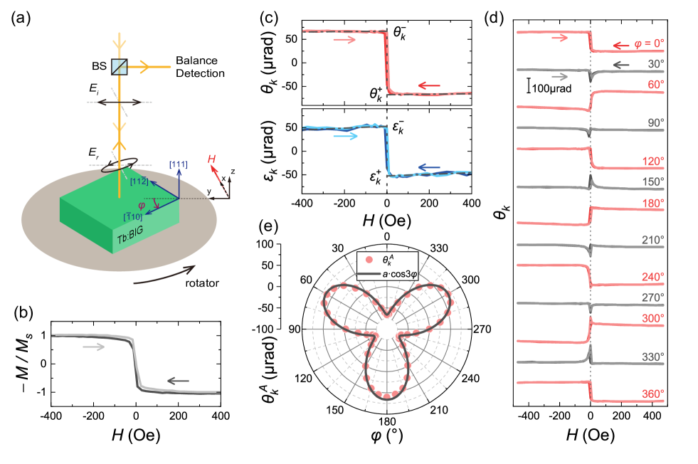
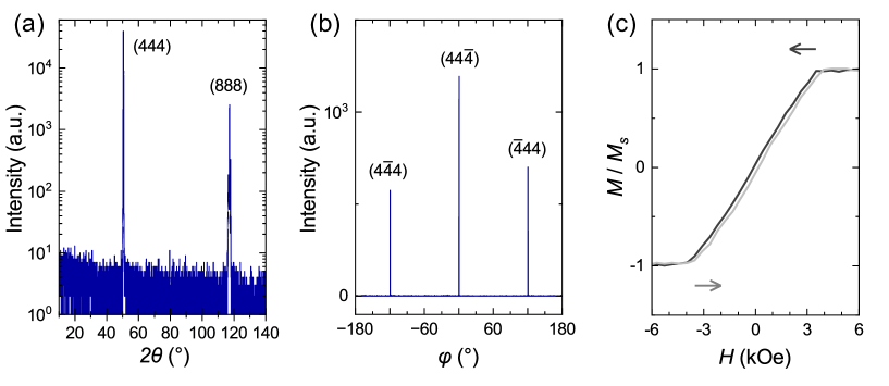
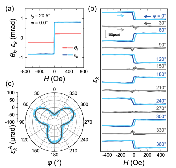
Our experimental investigations begin with the detection of the orthogonal MOKE in a 1- (Tb:BIG) single crystal film with space group , which belongs to the garnet family widely used as magneto-optical materials [?,?]. Figure 2a depicts the experimental setup of the orthogonal MOKE measurement on the Tb:BIG(111) sample. A pronounced asymmetric signal with respect to is detected in both Kerr rotation and Kerr ellipticity when , as shown in Fig. 2c, echoing the in-plane - curve of the sample in Fig. 2b. Since the Tb:BIG sample exhibits strong in-plane magnetic anisotropy with the saturation field below 50 Oe, the sudden jump in Kerr signal within 50 Oe is attributed to the in-plane rather than the out-of-plane magnetization. This result confirms that an -odd Kerr signal is generated in Tb:BIG by perpendicular to the light, which is in accordance with the orthogonal MOKE illustrated in Fig. 1c. The asymmetric components of the orthogonal MOKE signal, and , are quantified as and , which are well above the measurement noise level of approximately . It is worth noting that the Kerr rotation of the orthogonal MOKE almost amounts to 30% of the longitudinal MOKE signal as shown in extended Fig. 2a, highlighting it as a substantial effect.
Figure 2d presents the -sweeping results of when the in-plane orientation angle of the sample varies, showing that the signal exhibits a three-fold symmetry. Since the in-plane rotation of the sample does not alter the orthogonal geometry between and the probing light, we can conclude that the crystalline direction of in Tb:BIG determines the magnitude and sign of the orthogonal MOKE signal. The values of at different , shown in Fig. 2e, are accurately fitted with the function , which is exactly the (111)-face contributions of octupole, 32-pole and 128-pole according to Eq. 1, as detailed in Section II of the supplementary material. The -periodic sinusoidal relationship is distinct from the familiar period originating from the dipole term in most MOKE measurements and rules out the vicinal surface as the origin [?,?]. Therefore, the results in Tb:BIG demonstrate the feasibility of the orthogonal MOKE originating from the multipolar structure of Berry curvature in garnet materials.
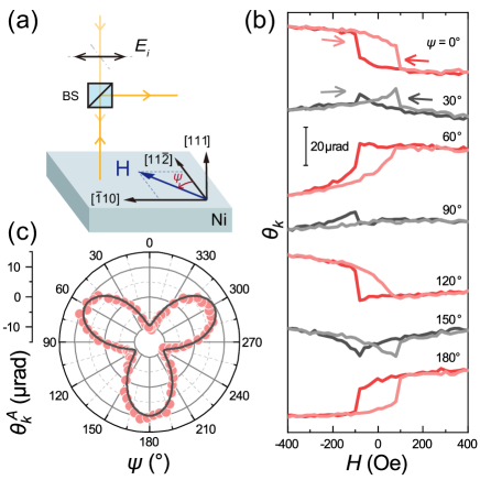
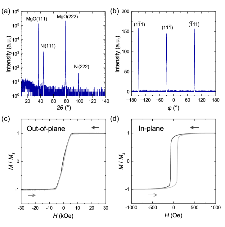
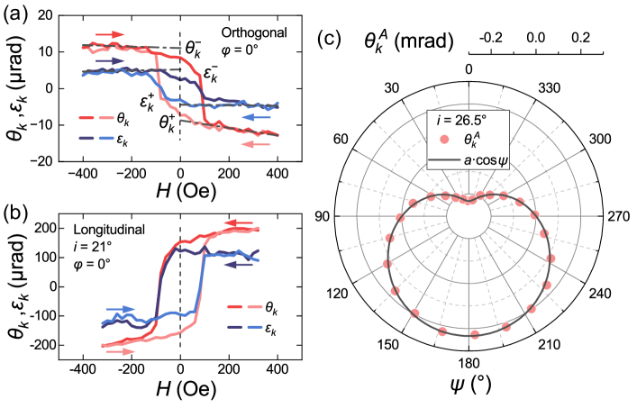
We now proceed to demonstrate the orthogonal MOKE in ferromagnetic metals [?,?,?], such as Ni, which are widely recognized as popular magneto-optical materials, together with garnet ferrimagnets. Figure 3a illustrates the measurement setup of the orthogonal MOKE in a 87-nm fcc Ni(111) film. Figure 3b presents the field sweeping results of Kerr rotation at different directions of , showing oscillating hysteresis loops similar to those observed in Tb:BIG. The asymmetric components at different , shown in Fig. 3c, are also well fitted with the function , confirming the same -multipole Berry curvature origin as in Tb:BIG, despite the difference between ferrimagnetic insulators and ferromagnetic metals. The observations in Ni and Tb:BIG reveal the common existence of -multipole-induced orthogonal MOKE in conventional cubic ferromagnets.
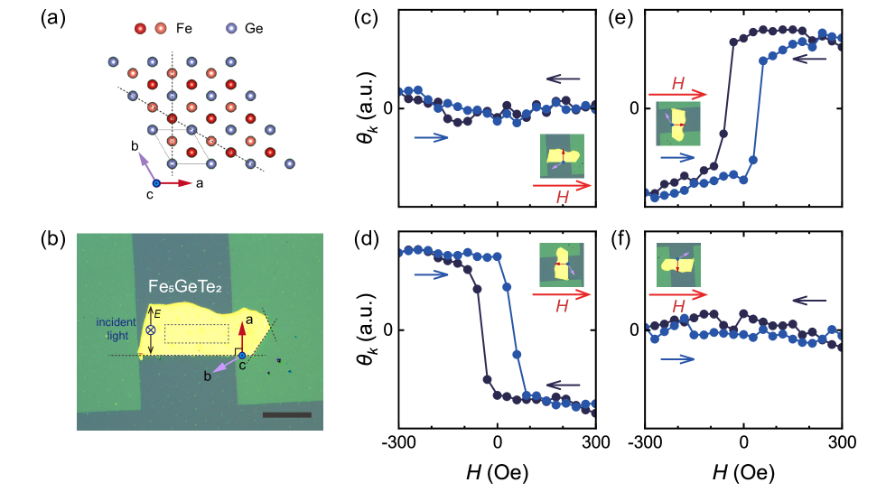
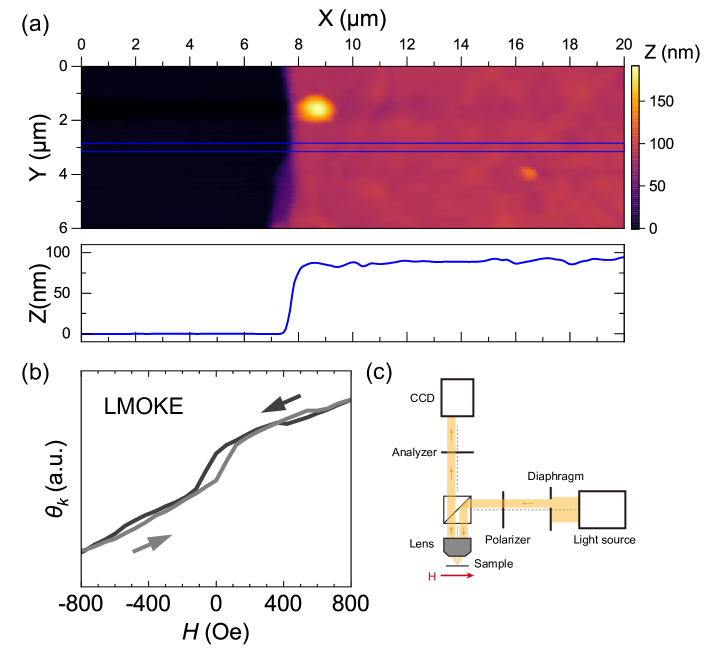
Finally, we demonstrate orthogonal MOKE in a van der Waals ferromagnet, a material family that heavily relies on MOKE for magnetic characterization [?,?,?,?,?] and exhibits emergent magneto-optical phenomena [?]. Here we investigate the orthogonal MOKE in , a typical van der Waals ferromagnet with lower crystal symmetry than cubic lattice. Figure 4a illustrates the atomic structure of along axis. Figure 4b shows the 88-nm sample used in experiment, with an in-plane saturation field smaller than 100 Oe at 200 K. When is perpendicular to the axis of , no magnetic field dependence in Kerr rotation is observed (Figure 4c). However, when is aligned with the axis, a pronounced hysteresis loop appears, indicating the in-plane magnetization (Figure 4d). To assess any longitudinal MOKE contribution from potential imperfect normal reflection, the sample is rotated 180 degrees while maintaining its inclination with a gradienter. After rotation, no magnetization dependence is observed when is perpendicular to the axis (Figure 4f), while an inverted hysteresis loop appears when is parallel to the axis (Figure 4e), confirming the presence of the orthogonal MOKE signal in sample. Given the symmetry breaking in , the -dipole contribution is shown to be incapable of generating the orthogonal MOKE, as elaborated in Section III of the supplementary material. Therefore, the detected signal must originate exclusively from the -multipole of Berry curvature.
We are now in a position to outline the general symmetry requirements for enabling the orthogonal MOKE geometry. When considering the dipole contribution of Berry curvature in space, the orthogonal geometry necessitates that the sample retains at most a mirror reflection symmetry, the plane of which is perpendicular to the sample surface, or a rotation symmetry, the axis of which is parallel to the sample surface [?], as in the vicinal interface sensitive MOKE [?,?]. In contrast, the orthogonal geometry in the case of multipole contributions only requires the absence of both and symmetries in the sample, where denotes the direction perpendicular to the sample surface, being much less restrictive. For instance, the orthogonal MOKE can typically be expected in single-crystalline samples with a cubic lattice, except for crystals oriented along (001) or (011) planes, which preserve the symmetry [?]. In polycrystalline samples, however, the orthogonal MOKE signals from individual grains cancel each other out, rendering the overall signal undetectable in transverse MOKE measurements [?], where the Poynting vector is orthogonal to the magnetization. For crystals with lower symmetry than cubic, the conditions for orthogonal MOKE are more easily satisfied, broadening its observability. For example, van der Waals ferromagnets such as [?], [?], [?], [?], [?], [?], and [?] all meet these criteria. Our measurements of the orthogonal MOKE in Bi:TIG, Ni, and provide comprehensive verification of this symmetry guideline, underscoring orthogonal MOKE as a powerful technique for characterizing magnetization and crystal orientation in van der Waals ferromagnets at the microscale.
The orthogonal MOKE can be readily implemented in various magneto-optical measurements, introducing new functionalities that enhance traditional techniques. For instance, it enables Kerr microscope to monitor the domain structures in ferromagnetic films with in-plane magnetization normally incident light [?,?,?]. Additionally, the orthogonal MOKE introduces in-plane magnetization sensing capabilities to the Sagnac interferometer MOKE, which operates solely through normally reflected light and achieves nanoradian sensitivity [?]. Although the orthogonal MOKE signal may contribute only a fraction of the longitudinal signal, e.g., for Kerr rotation in Tb:BIG, the three-order improvement in measurement accuracy provided by the Sagnac MOKE could make the orthogonal MOKE signal a superior probe for ultra-weak in-plane magnetic moments, which are crucial for understanding the spin generation in nonmagnetic materials as in the spin Hall effect and orbital Hall effect [?,?].
Beyond the immediate application of the orthogonal MOKE in magnetization characterization, the exploration of additional magneto-optical effects originating from magnetization multipoles holds great promise. Firstly, the orthogonal geometry of magneto-optical effect across different wavelengths—such as microwave, terahertz, and infrared—is ready for investigation, given their shared origin in Berry curvature [?,?]. Secondly, the orthogonal geometry of the Faraday effect is highly anticipated due to its common physical foundation with the MOKE [?], potentially giving rise to a plethora of new optical devices. For example, if a ferromagnet with in-plane magnetic anisotropy can demonstrate significant Faraday rotation in the orthogonal geometry, it becomes feasible to realize an orthogonal magnetic wave plate or Faraday isolator that does not require an external magnetic field [?]. The Faraday rotation of such an orthogonal device can be tuned via the direction of the in-plane magnetization, providing an additional degree of freedom not available in conventional Faraday rotators [?]. Overall, the advent of orthogonal magneto-optical phenomena opens new frontiers in both fundamental physics and technological innovation, paving the way for inventing magneto-optical devices with unprecedented functionality and tunability.
Methods
Sample growth and characterization.
The micrometer-thin Tb:BIG film was prepared by the standard liquid phase epitaxy (LPE) method from - based high-temperature solutions at 855 . The Ca, Mg, Zr substituted gadolinium gallium garnet (sGGG, 111, Saint-Gobain) was used as the substrate. Firstly, the high-purity powders (99.999% metal basis) of , , and were thoroughly mixed in a platinum crucible. In this case, the ratio of powders was 1:86:11:5. The mixture was melted at 1000 in the vertical tube LPE furnace, stirred with a platinum rotator until uniform. Then the solution was rapidly cooled at 100 /h down to the growth temperature and maintained a supersaturation state. Next, the substrates horizontally dipped into melt and initiated epitaxy. During the epitaxy, the substrate rotated with rate of 100 rpm for 1 min. After epitaxy, the sample was pulled out from the solution and rotated at 300 rpm to get rid of the liquid solution remnants. Finally, nitric acid cleaning was performed on the sample to obtain a smooth surface.
The Tb:BIG sample is characterized by X-ray diffraction (XRD), vibrating sample magnetometer (VSM) and Faraday effect, as shown in Fig.2b and extended Fig.1, which exhibits high-quality monocrystallinity and in-plane magnetic anisotropy. The longitudinal MOKE signal is measured, as shown in extended Fig. 2c.
The Ni(111) thin film was grown on MgO(111) substrate by DC magnetic sputtering [?] at the temperature of , with pre-annealing at for and post-annealing at for . A 4 nm Al coating layer was deposited on the Ni film at room temperature and oxidized in the atmosphere. The Ar pressure and DC power were set to and . The XRD and VSM characterization results are shown in extended Fig.3.
The growth and characterization of bulk is described in the literature by Peng Li [?]. The sample was exfoliated onto an oxidized silicon substrate. The thickness is determined as 88 nm by atomic force microscopy, as shown in extended Fig. 5a. The longitudinal MOKE result is shown in extended Fig. 5b, with experiment setup shown in extended Fig. 5c.
MOKE measurement setup.
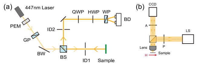
In the MOKE measurements in Tb:BIG and Ni, we use the Toptica iBeam Smart laserset as the source of light. The full optical path is shown in extended Fig. 6a. A photoelastic modulator is used to modulate the intensity of light from laserset at . Then, the light is polarized by a Glan prism and Brewster window. To ensure that the incident light is perpendicular to the sample surface, an iris diaphragm (ID1) with a diameter of 0.8 mm is placed in the path of light at a distance of about 145 mm from the sample. When the reflected light is adjusted to pass through ID1, the misaligned angle from normal incidence can be controlled within . Another diaphragm ID2 is placed after beam splitter to control the normal reflection during the sample rotation. After reflection from the sample, the rotation and ellipticity of light is measured by a quarter-wave plate (QWP), half-wave plate (HWP), Wollaston prism (WP) and balance detector (BD, Thorlabs PDB210A) [?]. The output electric signal of BD is demodulated at by two lock-in amplifiers (CIQ Melab, SINE OE1022) to get the absolute value of Kerr rotation and ellipticity. The signs of Kerr rotation () and Kerr ellipticity () are defined in accordance with the Stokes vector [?].
The Kerr microscopy used in this study is a commercial MOKE microscopy system from TUOTUO, which has a LED as the light source, an in-plane electromagnets and a wet cooling system using liquid nitrogen. The orthogonal geometry measurement is shown in extended Fig. 6b. The light is polarized and detected by wire grid polarizers. The magnetic field is applied in the sample plane. For the longitudinal measurement in Kerr microscopy, an off-axis diaphragm is inserted to achieve oblique incidence of light, as shown in extended Fig. 5.
Details of data analysis.
The asymmetric Kerr rotation () in Tb:BIG and Ni sample is defined as , where and are the intercepts of Kerr signal in the positive and negative saturated regions, obtained through linear fitting, as shown in Fig. 2c. Similarly, the asymmetric Kerr ellipticity is defined as . The saturated regions used for linear fitting is for the Tb:BIG sample and for the Ni sample.
The Orthogonal MOKE signal of Tb:BIG around zero field is explained by the deviation of from direction with additional quadratic MOKE contribution. In the measurement of Ni, the non-zero residual magnetization and the change in polarization with respect to contribute a butterfly-shape quadratic MOKE signal around zero field.
References
- 1. Z. Q. Qiu, S. D. Bader, Rev. Sci. Instrum. 71, 1243 (2000).
- 2. K. Schouhamer Immink, J. Braat, J. Audio Eng. Soc. 32 (1984).
- 3. D. Jenkins, et al., Microsyst. Technol. 10, 66 (2003).
- 4. J. Kerr, The London, Edinburgh, and Dublin Philosophical Magazine and Journal of Science 3, 321 (1877).
- 5. J. Kerr, The London, Edinburgh, and Dublin Philosophical Magazine and Journal of Science 5, 161 (1878).
- 6. C. A. Fowler, E. M. Fryer, Phys. Rev. 94, 52 (1954).
- 7. M. Freiser, IEEE Trans. Magn. 4, 152 (1968).
- 8. J. Zak, E. Moog, C. Liu, S. Bader, J. Magn. Magn. Mater. 89, 107 (1990).
- 9. A. K. Zvezdin, V. A. Kotov, Modern magnetooptics and magnetooptical materials (CRC Press, 1997).
- 10. N. Nagaosa, J. Phys. Soc. Jpn. 75, 042001 (2006).
- 11. N. Nagaosa, J. Sinova, S. Onoda, A. H. MacDonald, N. P. Ong, Rev. Mod. Phys. 82, 1539 (2010).
- 12. D. Hou, et al., Phys. Rev. Lett. 114, 217203 (2015).
- 13. A. V. Petukhov, A. Kirilyuk, T. Rasing, Phys. Rev. B 59, 4211 (1999).
- 14. J. Hamrle, et al., Phys. Rev. B 67, 155411 (2003).
- 15. L. Wang, et al., Phys. Rev. Lett. 132, 106601 (2024).
- 16. W. Peng, et al., arXiv:2402.15741 (2024).
- 17. Z. Liu, M. Wei, D. Hou, Y. Gao, Q. Niu, arXiv:2408.08810 (2024).
- 18. Q. Ma, et al., Nature 565, 337 (2019).
- 19. I. Sodemann, L. Fu, Phys. Rev. Lett. 115, 216806 (2015).
- 20. Q. Ma, A. G. Grushin, K. S. Burch, Nat. Mater. 20, 1601 (2021).
- 21. Y. Yao, et al., Phys. Rev. Lett. 92, 037204 (2004).
- 22. S.-Y. Xu, Physics 17, 38 (2024).
- 23. Y. Yang, T. Liu, L. Bi, L. Deng, J. Alloys Compd. 860, 158235 (2021).
- 24. L. Zhang, et al., J. Adv. Ceram. 12, 873 (2023).
- 25. E. Moog, S. Bader, Superlattices Microstruct. 1, 543 (1985).
- 26. K. Buschow, P. van Engen, R. Jongebreur, J. Magn. Magn. Mater. 38, 1 (1983).
- 27. M. Gaerner, R. Silber, T. Peters, J. Hamrle, T. Kuschel, Phys. Rev. Appl. 22, 024066 (2024).
- 28. C. Gong, et al., Nature 546, 265 (2017).
- 29. B. Huang, et al., Nature 546, 270 (2017).
- 30. Z. Fei, et al., Nat. Mater. 17, 778 (2018).
- 31. A. F. May, et al., ACS Nano 13, 4436 (2019).
- 32. A. Bedoya-Pinto, et al., Science 374, 616 (2021).
- 33. X. Li, et al., Nat. Phys. 20, 1145 (2024).
- 34. H. Pan, Z. Liu, D. Hou, Y. Gao, Q. Niu, Phys. Rev. Res. 6, L012034 (2024).
- 35. D. A. Allwood, et al., Appl. Phys. Lett. 92, 072503 (2008).
- 36. K. Postava, et al., J. Magn. Magn. Mater. 172, 199 (1997).
- 37. L. Alahmed, et al., 2D Mater. 8, 045030 (2021).
- 38. Y. Wen, et al., Nano Lett. 20, 3130 (2020).
- 39. X. Sun, et al., Nano Res. 13, 3358 (2020).
- 40. L. Liu, et al., Science 336, 555 (2012).
- 41. M. Yamanouchi, D. Chiba, F. Matsukura, T. Dietl, H. Ohno, Phys. Rev. Lett. 96, 096601 (2006).
- 42. J. Xia, Y. Maeno, P. T. Beyersdorf, M. M. Fejer, A. Kapitulnik, Phys. Rev. Lett. 97, 167002 (2006).
- 43. J. Sinova, S. O. Valenzuela, J. Wunderlich, C. H. Back, T. Jungwirth, Rev. Mod. Phys. 87, 1213 (2015).
- 44. Y.-G. Choi, et al., Nature 619, 52 (2023).
- 45. C. L. Hogan, The Bell System Technical Journal 31, 1 (1952).
- 46. J. Walowski, M. Münzenberg, J. Appl. Phys. 120, 140901 (2016).
- 47. P. N. Argyres, Phys. Rev. 97, 334 (1955).
- 48. P. Sandström, E. B. Svedberg, J. Birch, J.-E. Sundgren, MRS Online Proceedings Library 528, 209 (1998).
Acknowledgments: The author acknowledges Timo Kuschel for valuable discussion. This work was supported by the National Key R&D Program under grant Nos. 2022YFA1403502, 2023YFA1406400, the National Natural Science Foundation of China (12234017, 12074366, 12174364), the Fundamental Research Funds for the Central Universities (Grant No. WK9990000116). Z. Liu is supported by the National Natural Science Foundation of China (11974327 and 12004369), Fundamental Research Funds for the Central Universities (WK3510000010, WK2030020032), Anhui Initiative in Quantum Information Technologies (No. AHY170000), and Innovation Program for Quantum Science and Technology (2021ZD0302800). The setup of magnetic sputtering system and thin film growth was assisted by Anhui epitaxy technology co. Ltd. The sample fabrication was supported by the USTC Center for Micro- and Nanoscale Research and Fabrication.
Author contributions: H. Pan and D. Hou designed the experiment. H. Li and Q. Yang grew the Tb:BIG sample. H. Pan grew the Ni sample. J. Huang and P. Li fabricated the sample. H. Pan , M. Fang and W. Peng performed characterization of the Ni and Tb:BIG sample. H. Pan and M. Fang carried out the MOKE measurements in the Ni and Tb:BIG sample. X. Hu, X. Chang and Z. Sheng tested the magneto-optical property of the sample. Y. Jia and L. Wang provided Bi:YIG sample for magneto-optical testing. H. Pan, Y. Yuan, D. Liu and Q. Li carried out the MOKE measurement in the sample. H. Pan, X. Chen and D. Hou analyzed the experiment data. Z. Liu, D. Hou, Q. Niu and Y. Gao developed the explanation of the experiment. H. Pan and D. Hou wrote the manuscript. All authors discussed the results and commented on the manuscript.
Competing interests: The authors declare that they have no competing interests.