An Optical Interconnect for Modular Quantum Computers
Abstract.
Much like classical supercomputers, scaling up quantum computers requires an optical interconnect. However, signal attenuation leads to irreversible qubit loss, making quantum interconnect design guidelines and metrics different from conventional computing. Inspired by the classical Dragonfly topology, we propose a multi-group structure where the group switch routes photons emitted by computational end nodes to the group’s shared pool of Bell state analyzers (which conduct the entanglement swapping that creates end-to-end entanglement) or across a low-diameter path to another group. We present a full-stack analysis of system performance, a combination of distributed and centralized protocols, and a resource scheduler that plans qubit placement and communications for large-scale, fault-tolerant systems. We implement a prototype three-node switched interconnect and create two-hop entanglement with fidelities of at least 0.6. Our design emphasizes reducing network hops and optical components to simplify system stabilization while flexibly adjusting optical path lengths. Based on evaluated loss and infidelity budgets, we find that moderate-radix switches enable systems meeting expected near-term needs, and large systems are feasible. Our design is expected to be effective for a variety of quantum computing technologies, including ion traps and superconducting qubits with appropriate wavelength transduction.
1. Introduction
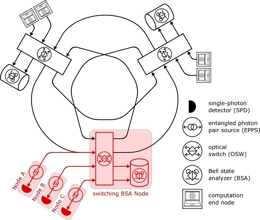
[Three nodes and switches arranged in a triskele.]Three nodes and switches arranged in a triskele. Each switch has an arrow connecting it to the next group counter-clockwise around the loop. Each switch has two computational node connected to it. One group is in red with 3 end nodes (the additional node is considered as the alternative input to the red group switch).
Recognition is growing that alongside designing monolithic architecture (Arute et al., 2019; Steffen et al., 2011; Murali et al., 2019; Min et al., 2023), modular architectures are the critical pathway to truly scalable quantum computers (Van Meter and Devitt, 2016; Awschalom et al., 2021; IBM, 2024). Single devices, such as a single superconducting chip or an ion trap, are limited to at most a few thousand physical qubits, but fault-tolerant systems of sufficient scale to solve large problems will require huge numbers of qubits, with proposed systems ranging well into the millions. One proposed direction to achieve this level of scale is for quantum nodes to hold one or more logical qubits, and perform logical gates remotely or by teleporting data (Oi et al., 2006; Van Meter III, 2006; Nagayama, 2017; Ahsan et al., 2015; Guinn et al., 2023; Leone et al., 2024; Isailovic et al., 2006). Other proposals rely on error correction code words that span multiple nodes (Jiang et al., 2007; Van Meter et al., 2010; Nickerson et al., 2013, 2014; de Bone et al., 2024). Recent work has also studied the possibility of noisy intermediate-scale quantum (NISQ) multicomputers (Ang et al., 2024; Preskill, 2018). Regardless of the approach taken towards scalability, interconnects are widely recognized as being crucial not only for performance but also for correctness and robustness of computation.
The challenge is to demonstrate that the physical system will scale up in number of end nodes as we increase the size and complexity of the switching network, which will negatively affect the key metrics of photon loss (measured in decibels) and fidelity, a measure of the quality of a quantum state; roughly, the probability that the system currently holds the state it should hold. Quantum interconnect architectures can learn from classical multicomputer architectures, which are the standard approach to supercomputing systems today (Athas and Seitz, 1988; Dally and Towles, 2004; Ajima et al., 2009; Kim et al., 2008; Shpiner et al., 2017; Stunkel et al., 2020; De Sensi et al., 2020; Besta and Hoefler, 2014). However, a number of key characteristics of quantum systems mean that this application is far from straightforward. We highlight these fundamental challenges below.
Every decibel matters. In classical systems with optical-electrical-optical switches or purely electrical switches, signals are regenerated at each switch. For quantum switches working at the level of single photons, this is fundamentally prohibited by the no-cloning theorem (Wootters and Zurek, 1982).
As a hypothetical example, if the loss in an optical path increases by 6dB, the performance will fall by a factor of four and so the memory lifetime demands will increase by a factor of four. This in turn might require us to raise the error correcting code distance, say from 9 to 11. Using the surface code (Fowler et al., 2009), this will result in times the physical qubits and 22 increase in the time needed for each logical gate, including the remote gates, resulting in slower performance at the hardware cost.
Overcoming the loss of individual photons requires complex nodes, known as quantum repeaters (Briegel et al., 1998), which are necessary in wide-area systems but which we would like to avoid in data center-scale systems. Instead, these systems are expected to rely on purely optical end-to-end paths. Thus, while network diameter influences performance, the loss across the group switch itself matters and, for some switch technologies, is strongly group size-dependent. These factors lead to the end-to-end decibel-oriented mantra above, rather than the “It’s ALL about the diameter,” mantra of Slimfly (Besta and Hoefler, 2014).
Error rates are very high. Even when received, the error rates for single photons, taking into account generation, propagation, switching, and measurement, typically amount to a few percent. This is far too high for correct computation, so entanglement generation will be followed by error detection in the form of purification (Dür and Briegel, 2007) or error correction (Devitt et al., 2013).
Operations are probabilistic. Another major impact on system performance is that some crucial operations are inherently probabilistic. A notable example is optical entanglement swapping, also known as Bell state analysis, where the success probability is fundamentally limited to 50% when implemented with linear optics. Failure of such probabilistic operations necessitates retrial at a significant performance cost.
Synchronization demands can be very strict. The length of a photon’s wave packet can range over a startlingly large six or more (decimal) orders of magnitude, depending on the chosen technology. In some cases, including our experiments, they can be as short as a couple of millimeters, which corresponds to only a few picoseconds. Since some tasks require that photons arrive simultaneously, our synchronization system must be tuned to a small fraction of that time.
The flow of photons is unidirectional, but applications can move data in either direction. Once the interconnect establishes entanglement between two end nodes, quantum teleportation (Bennett et al., 1993a) is used to move qubits from one node to another, or the entanglement is used to execute a remote quantum gate (Eisert et al., 2000; Van Meter et al., 2008). Once created, the behavior of the entanglement is independent of the directions in which the photons originally propagated.
Good detectors are expensive and require a cryogenic environment. Room temperature detectors are common but moderate in loss; given that multiple detectors must fire simultaneously, the multiplicative loss of performance is unacceptable. Current state of the art detectors are needed for each link, but these require a cryogenic environment, complicating physical layout. Moreover, fabrication yields are low and supporting electronics are complex.
Reconfiguring connections is slow and recalibration must be performed frequently. Reconfiguring the switches themselves is not the bottleneck in the process; in order to tune each new connection and ensure optimal operation, additional components (currently mechanical) must be adjusted. Such adjustments can take as long as a few seconds (Krutyanskiy et al., 2023), resulting in a significant decrease in overall system performance. Furthermore, due to the extreme sensitivity of single photons to environmental noise, the system must be frequently recalibrated, even if no new connections need to be accommodated.
Given these unique challenges, the current focus of modular quantum system research is the link (Alshowkan et al., 2022; Pompili et al., 2022) and connection layers (Rao et al., 2023; Alshowkan et al., 2021). This is a necessary first step towards building more complex systems. However, in order to bring us closer to scalable and robust distributed quantum systems, there is a pressing need for deeper understanding of higher-layer concepts such as switching network architectures, and their impact on the performance when executing large-scale quantum computation.
We address this need by presenting a full-stack architecture for a quantum switching network. Our approach is guided by the following principles:
-
•
In order to curtail the effect of photon loss, the switching interconnect architecture should minimize the number of hops and optical elements, while allowing connectivity between all pairs of end nodes.
-
•
The proposed architecture should be implementable with present-day hardware, and allow for fully reconfigurable and robust control.
-
•
The switching architecture must allow for efficient execution of distributed quantum computational primitives.
-
•
Finally, the architecture should provide a clear path for technological evolution.
Our contributions are summarized below.
-
•
We present a scalable switching architecture, referred to as “Q-Fly” (Fig. 1), based on the group and inter-group structure of the Dragonfly (Kim et al., 2008). This architecture avoids the higher hop counts of other network architectures such as fat trees (Leiserson, 1985; Leiserson et al., 1992). We introduce three Q-Fly topologies, with differing inter-group connectivities and optical path depths, and perform end-to-end loss analysis.
-
•
We experimentally implement a local group of the Q-Fly, given by three measurement end nodes, distributing entangled photon pairs via a switchable Bell state analyzer (BSA), as highlighted in red in Fig. 1. Using bulk optical elements and an automated, reconfigurable control system, we demonstrate excellent stability of the system, producing post-switched (two-hop) end-to-end fidelities in the range of 0.60-0.64 at an average rate of 5 Hz.
-
•
We project the performance of the Q-Fly architecture in a large-scale quantum computation by creating execution schedules for a distributed version of the quantum Fourier transform (QFT). We identify the parameter regimes where the Q-Fly topology performs more than 2 times faster than a 2D lattice, and only 2.1 times slower than a monolithic execution.
We begin by outlining the fundamental quantum technologies required for an optical switching network in Sec 2. Using these quantum primitives, we define three Q-Fly variants in Sec. 3, along with the quantum optical system implementing a group switch. We evaluate the performance of our experimental implementation in Sec. 4. In order to study the projected performance of Q-Fly in the context of large-scale fault-tolerant quantum computation in Sec. 5, we develop a qubit allocation procedure and network scheduler along with a distributed quantum computation performance evaluation tool. Finally, we discuss the set of conditions under which Q-Fly is a viable architectural choice in Sec. 6.
2. Quantum Network Primitives
Before introducing our Q-Fly architecture, we provide a brief overview of basic quantum networking concepts that will be used throughout the paper.
2.1. Entanglement as a Resource
Entanglement is a correlation shared between two or more quantum subsystems that has no parallel in classical systems (Horodecki et al., 2009). It is a fundamental resource that is exploited in the vast majority of quantum technologies, such as secure communication (Ekert, 1991), distributed quantum computing (Barral et al., 2024; Caleffi et al., 2024), and sensing (Gottesman et al., 2012).
The primary function of quantum networks is to distribute entanglement between distant nodes in order to enable these quantum applications. This is typically done with the help of pairs of photons entangled in their polarization degree of freedom. One such entangled state of photons and is denoted by , where denotes the horizontally/vertically polarized state of the photon. In a quantum network, these states are generated by the entangled photon pair source (EPPS). In reality, these state will be affected by various sources of noise, resulting in deviations from the ideal state . Such noisy states are denoted by the density operator , and represent our lack of knowledge about the real distributed state. Such deviations are quantified by fidelity, denoted by , which roughly represents the probability that the real distributed state is the ideal state . This is often represented as infidelity, defined as .
Entanglement generation between distant quantum systems that have not interacted previously is possible via entanglement swapping. Two different entangled states and can be used to generate an entangled state by performing a Bell measurement on qubits and , and communicating the outcome classically to and . The quantum network node that performs this two-qubit measurement is referred to as a Bell state analyzer (BSA). It is crucial to note that BSA nodes implemented with linear optics have a maximum theoretical success probability of 0.5 (Vaidman and Yoran, 1999).
It is important to note that entanglement is not directional. Quantum nodes and that share an entangled state can use this state to transfer quantum information from or from via quantum teleportation (Bennett et al., 1993b). In the context of distributed quantum computation, nodes and can also use to execute a remote quantum gate (Eisert et al., 2000).
2.2. Link Architectures
To focus on the direction of flow and latency of individual photons and the necessary classical messaging, link architectures are divided into three classes, based on the relative placement of quantum memories, EPPS nodes, and BSA nodes (Van Meter, 2014). Memory-Interference-Memory (MIM) links place the BSA between two quantum memory nodes. Each node emits a photon entangled with the stationary memory toward the BSA, where optical entanglement swapping is attempted. Upon success, the memory nodes share an entangled state. Memory-Source-Memory (MSM) links, or midpoint source links, instead create entangled photon pairs in the middle of the link and send them to the quantum memory nodes. Memory-memory (MM) links send photons all the way from one memory node to another, utilizing either absorptive memory or a BSA embedded within the receiving node to achieve entanglement. Our designs here focus primarily on MIM and MSM links.
In the Q-Fly, MIM optical paths will generally have one long arm and one short arm, as in the upper part of Fig. 2. To minimize loss, having only one arm pass through optical switches is advantageous, but networks that make that possible when only a single network interface is available at each node are difficult to configure. As a result, some of our designs pass both arms through switches. Alternatively, creating the equivalent of a full-duplex link requires two interfaces at each node and two fibers, but will allow us to pass one arm directly to the BSA without passing through a switch, as we will see in the next section.
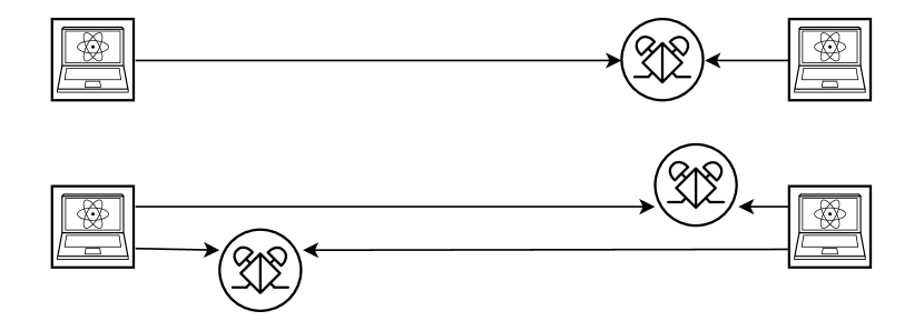
[The image shows two distinct types of connections between two quantum computational nodes.]At the top, two computational nodes are connected by a single BSA, which is positioned close to one of the nodes. Below, the two computational nodes are connected using two separate links, each with a BSA positioned in between. Each BSA is located closer to a different node.
3. The Q-Fly Topology and System Design
3.1. Network Topologies
The Q-Fly, like other “-fly” topologies, achieves scalability by attaching computational (and possibly measurement, storage and sensing) end nodes to switches in groups (Kim et al., 2008; Besta and Hoefler, 2014; Shpiner et al., 2017; Lakhotia et al., 2022). Each group can consist of a set of switches that are strongly interconnected. The groups are connected to each other via one or more links. The Dragonfly, for example, then provides three levels of connection, with different latencies and more importantly different aggregate bandwidths: intra-switch, with single-switch latency and concurrent all-to-all connections with bidirectional bisection bandwidth for nodes connected to the same switch; intra-group, which will be limited by the number of links from one in-group switch to another in-group switch; and inter-group, which will be limited by the number of links from one group to another group.
We develop quantum variants of the Dragonfly, where each group consists of a switch that supports full intra-group communication, and some ports of the switches are used for inter-group communication. Due to the need to route photons to BSAs, the architecture has only two tiers of connections: intra-group and inter-group. We introduce three Q-Fly architectures, as shown in Fig. 3. Our notation is listed in Tab. 1 and the construction parameters are compared in Tab. 2. In general, classical fly designs are drawn as undirected graphs and it is understood that each line represents a full duplex link, e.g. a pair of counter-propagating fibers. Here, we will always be explicit about photon propagation direction and lines in the figures are assumed to be single-direction channels.
Single-path, quasi-half duplex topologies are constructed by placing the groups in a circle, as shown in Fig. 3(a). Each of the end nodes in a group has one unidirectional connection from the node to a group switch. The outputs of the switch are divided into two sets; ports to the BSAs in the BSA pool and ports to other groups. The group switch radix is . Each group adds a fiber from itself to every group on its right, going counterclockwise, stopping before reaching halfway across the system. If the number of groups is even, an additional set of fibers is added crossing the diameters of the circle. Note that each end node has only a single interface. This architecture is the simplest to build, but has the lowest inter-group bandwidth and provides no fault tolerance for single-hop group-to-group connections.
Dual-path, quasi-half duplex topology is shown in Fig. 3(b). Each group adds a fiber from itself to every group on its right, going counterclockwise, continuing all the way around the system. Each of the end nodes in a group has one unidirectional connection from the node to a group switch. The outputs of the switch are divided into two sets; ports to the BSAs in the BSA pool and ports to other groups. The group switch radix is . Note that a fiber carries single photons from every group to every other group. This means that each pair of groups is connected by two fibers running in opposite physical directions, providing bandwidth and fault tolerance. However, each end node has only a single interface, making the connections quasi-half duplex.
Dual-path, quasi-full duplex topologies are depicted in Fig. 3(c). Unlike previous cases, the end nodes have two interfaces. One interface of each of the end nodes is connected directly to one port of a currently unconnected group BSA, and the second port is connected to an input port of the group switch. Next, one output port from the group switch is connected to the second port of each of the BSAs. The remaining group switch ports are dedicated to inter-group communication, following the same procedure as the dual-path, quasi-half duplex topology. Note that the number of nodes supported for a given radix is the same as the dual-path, quasi-half duplex configurations, but twice as many BSAs and detectors are needed.
[The figures are vertically illustrated in three sub-figures, each showing a different configuration of a Q-Fly with five switch groups arranged in a circular layout. Each group connects four quantum computational nodes to the left side of a switch, and a group of BSAs with varying counts is located on the right side of the switch. The interconnections between the switches differ in each sub-figure.]In sub-figure (a) Each switch group has 6 input and 6 output ports. Four of the input ports are connected to computational nodes, while the remaining two come from two switches on the left. Among the six output ports, four are connected to BSAs, and the remaining two connect to two switches on the right. Sub-figure(b) is similar to (a), but each switch group has 8 input and 8 output ports. Additionally, all switches are fully interconnected. The interconnections between switch groups in sub-figure (c) are similar to (b), but each computational node has an additional link directly connected to a specific BSA. As a result, there are four BSAs instead of two on the right side of each switch.
| number of end nodes in fully populated system | |
| number of groups in fully populated system | |
| group size (number of quasi-half duplex end nodes attached to one group switch) | |
| group size (number of quasi-full duplex end nodes attached to one group switch) | |
| group switch radix (i.e., inputs and outputs) | |
| number of BSAs in one group (each 4 detectors, 2 switch egress ports) | |
| number of detectors in total system (BSAs only) |
| Type | or | |||||
| SPHD | 6 | 20 | 5 | 4 | 2 | 40 |
| DPHD | 6 | 12 | 3 | 4 | 2 | 24 |
| DPFD | 6 | 12 | 3 | 4 | 4 | 48 |
| SPHD | 8 | 36 | 9 | 4 | 2 | 72 |
| DPHD | 8 | 20 | 5 | 4 | 2 | 40 |
| DPFD | 8 | 20 | 5 | 4 | 4 | 80 |
| SPHD | 12 | 78 | 13 | 6 | 3 | 156 |
| DPHD | 12 | 42 | 7 | 6 | 3 | 84 |
| DPFD | 12 | 42 | 7 | 6 | 6 | 168 |
| SPHD | 16 | 136 | 17 | 8 | 4 | 272 |
| DPHD | 16 | 72 | 9 | 8 | 4 | 144 |
| DPFD | 16 | 72 | 9 | 8 | 8 | 288 |
| SPHD | 24 | 300 | 25 | 12 | 6 | 600 |
| DPHD | 24 | 156 | 13 | 12 | 6 | 312 |
| DPFD | 24 | 156 | 13 | 12 | 12 | 624 |
| SPHD | 64 | 2080 | 65 | 32 | 16 | 4160 |
| DPHD | 64 | 1056 | 33 | 32 | 16 | 2112 |
| DPFD | 64 | 1056 | 33 | 32 | 32 | 4224 |
| SPHD | 128 | 8256 | 129 | 64 | 32 | 16512 |
| DPHD | 128 | 4160 | 65 | 64 | 32 | 8320 |
| DPFD | 128 | 4160 | 65 | 64 | 64 | 16640 |
| SPHD | 576 | 166176 | 577 | 288 | 144 | 332352 |
| DPHD | 576 | 83232 | 289 | 288 | 144 | 166464 |
| DPFD | 576 | 83232 | 289 | 288 | 288 | 332928 |
| SPHD | 1100 | 605550 | 1101 | 550 | 275 | 1211100 |
| DPHD | 1100 | 303050 | 551 | 550 | 275 | 606100 |
| DPFD | 1100 | 303050 | 551 | 550 | 550 | 1212200 |
3.2. Construction of a Group Switch
When constructing the group switch, it is essential to analyze the performance and loss of currently available full-optical switching technologies. Different choices of switch architecture, topology, and switching mechanism have a significant impact on performance indicators such as insertion loss. We consider three types of components for the construction of group switches: discrete 22 switches, planar photonic chips, and switches. We define the fiber-to-BSA insertion loss of a -radix group switch as GroupLoss().
When the group switch is constructed from discrete switches, we can use a Beneš network, which requires a switch depth of . We let [dB] be the fiber-to-fiber insertion loss of a switch. In this setting, the fiber-to-BSA insertion loss of -radix group switch, denoted by GroupLoss(), becomes [dB].
For planar photonic chips, which are restricted to a planar arrangement of switch cells, we can use a planar permutation network (Spanke and Benes, 1987), requiring a switch depth of . Given [dB] and [dB] as the coupling loss and the switching cell loss respectively, GroupLoss() becomes [dB].
If the group switch is constructed from a single switch with dB insertion loss, GroupLoss() is simply .
4. Prototype Implementation
We demonstrated the feasibility of our architecture by constructing the red portion of Fig. 1. This corresponds to entanglement distribution between two nodes selected by a network protocol through a group switch. It reveals the actual procedure of the entanglement distribution and provides insight into performance estimation.
4.1. Design of the Prototype
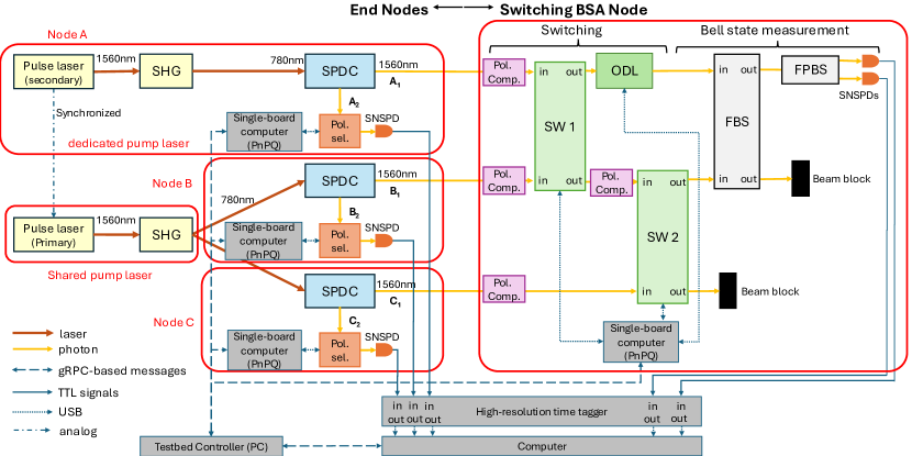
[This diagram illustrates the overall setup for the experiment]Boxes and arrows showing the flow of both photons and control signals, from the pump laser, through SHG and SPDC, through the switches, and to the measurement setups. Control computers and signals are included.
The experimental setup is shown in Fig. 4. Each of the three end nodes (A, B, C) can generate entangled photon pairs and measure one of the pair, and the switching BSA node links any pair of end nodes via entanglement swapping. At end node A, a mode-locked laser at (repetition rate: , pulse width: , spectral width: ) is amplified by an erbium-doped fiber amplifier (EDFA), and then frequency doubled by second harmonic generation (SHG). The SHG light at pumps degenerate the photon pair at by spontaneous parametric down conversion (SPDC) in a type-II PPLN waveguide. By separating the photon pair into two different spatial paths using a half beamsplitter (HBS), the photon pair in the polarization entangled state of is prepared in a postselection manner with probability of 0.5.
The photon in mode (path) is coupled to a single-mode fiber (SMF) and sent to the switching BSA node. In contrast, the photon at mode passes through a polarization selector (Pol. sel.) composed of a quarter-wave plate (QWP), a half-wave plate (HWP), and a polarizing beamsplitter (PBS). Then, it is coupled to an SMF and sent to the detector for node A.
At nodes B and C, another mode-locked pulse laser is used. The repetition rate is , which is determined by the internal clock of the laser device. The clock signal is connected to the laser source used in node A to synchronize their repetition rates. After the SHG, the pulse is coupled to a polarization-maintaining fiber and distributed as the pump lights to prepare the SPDC photon pairs and at nodes B and C, respectively. Like node A, the photons in modes and are sent to the switching BSA node, and the photons in modes and are detected locally.
At the switching BSA node, two of the three photons , and are selected using two optical switches (SW 1 and SW 2) as inputs to the BSA, which is composed of a fiber-based beamsplitter (FBS), then a fiber-based polarizing beam splitter (FPBS), and finally two single-photon detectors. The BSA succeeds when the photons are detected at the two different detectors, which occurs with probability of . This transforms the two-photon states at the end nodes and () from . For a successful entanglement swap, the polarization of each photon is adjusted by a polarization compensator. The arrival times of the photons are adjusted using an optical delay line (ODL).
Each photon is spectrally narrowed by a frequency filter with the bandwidth of . All of the single-photon detectors used in this experiment are superconducting nanowire single-photon detectors (SNSPDs). Each of the SNSPDs has a time resolution of and a quantum efficiency of . The electrical signals coming from SNSPDs are collected by a multi-channel time tagger with a time resolution of .
4.2. Evaluation of the Prototype
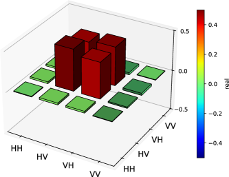
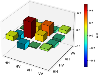
First, we evaluated the SPDC photon pairs produced at each node. At node (), by installing the polarization analyzer to the optical path of photon and directly connecting the SMF to the SNSPD without sending the photon to the repeater node, we performed the quantum state tomography of the photon pair in modes and . Using the iterative maximum likelihood method, we reconstructed the density operator (James et al., 2001). The result for node A is shown in Fig. 5. The fidelities of the photon pairs prepared at nodes A, B and C are , and , respectively. These results show that our nodes successfully prepare highly entangled states.
 \Description
[The diagrams shows a 3D representation of the real part of the density matrix related to node A]
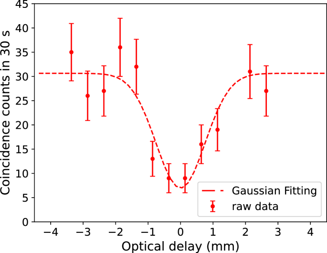
Next, we performed the Hong-Ou-Mandel (HOM) experiment to adjust the optical delays of the photons arriving from the different nodes (Hong et al., 1987). For example, for the HOM interference between the photons at modes and , the H-polarized photons are mixed by measuring the V-polarized photons at modes and . The experimental result of the HOM dip is shown in Fig. 6. From the best fit to the experimental data with Gaussian functions, the visibility of the HOM interference between the photons from modes and is estimated to be . Similar experiments related to modes and were performed. The visibilities of the HOM experiments are and , respectively.
 \Description
[This is the result of Hong-Ou-Mandel experiment shown in a diagram in red color.]The vertical axis represents the number of coincidence counts measured over 30 seconds ranging from 0 to 45. The horizontal axis is labeled as optical delay measured in millimeter and ranges from minus 4 millimeter to plus 4 millimeter. The diagram shows 12 spots illustrating the actual coincidence counts in different optical delay lengths. A dashed curved, based on Gaussian fit of the raw data points, is also included.
Finally, we performed entanglement swapping. In the experiment, we set the position of the ODL to the bottom of the dip. We reconstructed the density operators of the two-photon states after the entanglement swapping related to mode pairs , and . The result for mode pair is shown in Fig. 7. The fidelities of the states are , , and , respectively. The values are much higher than 0.5. Thus, we conclude that entanglement swapping with the switching operation was successfully demonstrated.
 \Description
[A 3D graph represents the real values of density matrix.]The x-axis and y-axis are labeled with four values HH, HV, VH, VV. The corresponding z-axis are displayed as 3D bars with different color based on their value. The color spectrum ranges from dark blue for value of -0.5, transitioning through green for values near zero to dark red color for 0.5). Among 16 z-axis values, the 3D bars at (HV, HV) and (VH, VH) are in red. Two other cubes represent (VH, HV) and (HV, VH) are in lighter shades of red. The remaining bars, representing values close to zero, are green.
4.3. Evaluation of Loss and Infidelity
We list the loss caused by each of the optical components in our experiment in Tab. 3.
| Photon | Component | Optical Loss [dB] |
| inside node inc. SNSPD | 14.7 (A), 14.3 (B), 14.8 (C) | |
| Optical switch (SW 1) | 0.46 | |
| Optical switch (SW 2) | 0.41 | |
| ODL | 1.37 | |
| FBS | 0.27 | |
| FPBS | 0.46 | |
| inside node inc. SNSPD | 17.2 (A), 14.5 (B), 14.5 (C) |
The infidelity after the entanglement swapping is mainly caused by the imperfection of the HOM visibility, caused by synchronization and polarization mismatch at the BSA. From the experimental parameters, the impacts of the bandwidth and the multi-photon effects of the SPDC process on the HOM visibility are both estimated to be 0.9. The effects of the other imperfections on the HOM visibility, such as polarization mismatch or fluctuations during the experiment and the imbalance between the transmittance and reflectance of the FBS, are 0.9 for node pair , and 0.8 for node pairs and . The effects of imperfections outside of the SPDC process are 0.96, 0.84 and 0.82 for node pairs , and .
5. Projected Performance of the Q-Fly
Having measured the performance of one group switch equipped with three end nodes, we can now evaluate the performance of production-scale systems. Since we focus on the interconnect, we restrict ourselves to a single choice on each of the other major system parameters: physical technology, node design, quantum error correcting code, compilation method, and application. Each computational node is designed for surface code error correction with lattice surgery (Fowler et al., 2012; Horsman et al., 2012; Tan et al., 2024). Computation is organized and compiled according to the Game of Surface Codes approach (Litinski, 2019; Liu et al., 2023a). Each node is internally organized into a set of tiles (which define the code distance), and one or more tiles is used as a patch to hold a single logical qubit. Some logical single-qubit gates must be decomposed into longer sequences of up to several hundred and gates, which in turn are executed on the surface code using gate teleportation (Ross and Selinger, 2016). We adopt Gidney’s state of the art state cultivation, in which preparation of the ancilla state needed for non-Clifford gates costs about the same as a lattice surgery CNOT (Gidney et al., 2024) 111It is worth emphasizing Gidney’s observation that cultivation is the end point of a series of innovations that have reduced the execution cost of magic state preparation by a factor of a thousand. This preparation will no longer be the performance bottleneck even in monolithic systems.. We choose a large-scale, -qubit quantum Fourier transform (QFT) consisting of gates as the workload, which is useful not only for Shor’s factoring algorithm, the related quantum phase estimation problem, and some forms of arithmetic, but also for Jordan et al.’s new decoded quantum interferometry (DQI) (Jordan et al., 2024; Shor, 1997; Yoshioka et al., 2024).
We focus on a two-level interconnect in the system, where qubit couplings within a node are all of a single, uniform type, and the inter-node connections are all optical. This is also for simplicity of analysis; multi-tier architectures were proposed some time ago and are in fact being built by some companies (Van Meter et al., 2010).
Inter-node logical two-qubit gates are assumed to be conducted by creating a physical Bell pair, transforming each of the two physical qubits into a logical qubit, performing purification (a form of error detection) using multiple logical Bell pairs, and finally using the high-fidelity Bell pair to perform lattice surgery-style logical gates (Nagayama et al., 2016; Horsman et al., 2012; Litinski, 2019; Eisert et al., 2000). We expect this approach to be higher performance than fully distributed lattice surgery (Guinn et al., 2023; Leone et al., 2024).
5.1. Two-node Entanglement Generation
We assess loss and infidelity caused by Q-Fly when entanglement generation is performed between two end nodes. Loss and infidelity depend mainly on the network topology of Q-Fly, the performance of the group switch, and the traffic pattern (due to the need for some connections to take a longer-than-shortest path when path contention occurs).
We assume that the entanglement generation process follows these steps over many application-specific rounds:
-
(1)
Pairs of nodes make requests for entanglement generation, in order to fulfill those nodes’ computational needs. These requests constitute our traffic pattern.
-
(2)
In order to fulfill those requests, the network protocol determines what the group switches’ state should be for a given round. In other words, the network protocol schedules the nodes’ requests for execution.
-
(3)
At set time intervals, the group switches’ state is reconfigured to match the next desired state.
-
(4)
Entanglement generation processes are executed until the end of the current round.
First, we consider the effect of steps 2, 3, and 4 on the overall entanglement generation rate between two nodes. In systems conducting a single, coordinated computation, step 2 is largely calculated at compilation time, along with the placement of variable qubits among the distributed nodes. We also need to consider when entanglement generation requests encounter congestion, such that requests are blocked waiting for resources to become available.
The main cost of step 3 is the time required for the group switches to change state, including ODL adjustment.
In step 4, the number of consecutive entanglement generations without switch state change depends on the application circuit and scheduling. The length of a round may depend on the amount of quantum memory each node has. Additional quantum memory enables the nodes to buffer entanglement for later use, so careful scheduling can reduce the number of switching rounds. For the remainder of this paper we assume that exactly one high-fidelity logical Bell pair is created per round. The length of the round, then, is the maximum of the values across the set of connections active in this round. To determine for each connection, we must evaluate the optical paths in use.
Assuming that the execution time of step 2 is negligible, the overall logical Bell pair generation time between two nodes is the physical Bell pair generation time times the number of physical Bell pairs required. Based on some assumptions about the cost of purification, we estimate that 80 physical Bell pairs are required, giving the time
| (1) |
and the final rate
| (2) |
where the first fraction is our duty cycle, the fraction of time the system is doing useful work. The duty cycle’s denominator is the total time for a round.
The critical criteria determining the performance of each individual optical path are loss and infidelity. These characteristics are dependent on the number of group switches total along both arms between the end nodes and the BSA, and on the loss of each group switch as a function of the group radix , which we will call and express in decibels. We introduce switch types and principles here, then evaluate concrete examples in the next subsection. Paths can be classified into two categories: intra-group and inter-group. Tab. 4 summarizes loss for each proposed network architecture and path type, as illustrated in Fig. 9.
 \Description
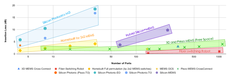
[The diagram illustrates insertion loss in various candidate switch technologies]The diagram’s horizontal axis represents the number of ports on a logarithmic scale, ranging from zero to 1000. The vertical axis is insertion loss in the scale of decibel ranging from zero to 20. The figure categorized different switch technologies or fabricated chips into five different categories: Silicon photonic category, using Mach-Zehnder Interferometer components, is positioned on the left-top side in blue color. The second category, labeled ”Homebuilt by 2x2” and shown in yellow, is located in the left side. The ”Hybrid Silicon+MEMS” category, shown in purple, is positioned in the middle of the diagram. The ”3D and piezo MEMS” category shown in green, spans from the left-bottom to the right-bottom side of the diagram. The fifth category, ”Fiber switching robot”, shown in red color, is located at the right-bottom side of the diagram
The actual values for GroupLoss() depend on the chosen switch technology. For example, fabrication of Mach-Zehnder switching components on silicon photonic chips is a promising technology, offering several benefits including a switching time ranging from nanoseconds in electro-optical switches (Dupuis et al., 2020; Qiao et al., 2017) to microseconds in thermo-optical switches (Suzuki et al., 2014; Tanizawa et al., 2015). However, as shown in Fig. 8 such switches suffer from significant fiber-to-fiber insertion loss that will grow as the group switch size increases.
In contrast, cross-connect MEMS technology enables high-radix switches with low fiber-to-fiber insertion loss (Calient, 2024; Inc., 2024; Kaman et al., 2007; Liu et al., 2023b), but with much slower switching time, typically on the order of a hundred milliseconds. These differing features have motivated design and fabrication of hybrid Silicon-MEMS devices, such as MEMS actuated vertical adiabatic couplers (Seok et al., 2016, 2019), to take advantage of the best qualities of each technology. This can increase switch scale while reducing insertion loss and switching time.
Finally, fiber-switching robots (Kewitsch, 2009; Telescent, 2024), designed for automation of topology management, offer lower insertion loss. However, their slow reconfiguration time, on the scale of minutes, limits their effectiveness in dynamic networks. Further performance improvements would be required to enable their use in quantum interconnection networks.
We summarize actual values of GroupLoss() based on our implementation and publicly available information in Fig. 8.
We assume that group switch infidelity originates from inaccuracies in polarization stabilization as well as imperfections in BSA measurements. Based on our laboratory measurements, we further assume that effects from the group switch itself are negligible. In this model, the infidelity caused by Q-Fly is independent from the configuration-dependent parameters Tab. 1. Based on our data, the infidelity caused by Q-Fly is about ten percent in our lab, a figure we will reuse here.
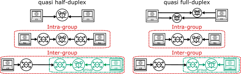
Rows of node icons showing flow of photons and number of switches crossed for each path type.
| Path type | ||
| quasi-half dup., 1 path | ||
| quasi-half dup., 2 path | ||
| quasi-full dup., 2 path |
5.2. Computation Time Estimation
With the above basis, we next evaluate the Q-Fly workload using a performance evaluation tool we have developed.
5.2.1. Evaluation setup and conditions
The magnitude of the overhead is inversely proportional to the transmission probability through the channel for each photon. Using Tab. 4, we can estimate the effective loss (Azuma et al., 2023) in single-path quasi-half duplex Q-Fly depicted in Fig. 3(a), in decibels, as
| (3) | ||||
The first term captures the effect of finite success probability at the BSA. The second term is the propagation loss in fiber between nodes separated by distance , with denoting the loss per kilometer in fiber, in decibels. The last term is at a single group switch. Assumed interconnect lengths range from several dozens to several hundreds of meters, meaning that for a loss of dB/km, photon loss in the fiber can be neglected. Q-Fly has directional connectivity between group switches and the number of hops, , is defined by the number of group switches on the path connecting end nodes.
To investigate behavior quantitatively, we assume that the group switch is Beneš’s non-blocking optical switch network (Spanke and Benes, 1987). Every photon passes through () switches within every group switch. Therefore, the insertion loss of every group switch with radix is roughly
| (4) |
where is the insertion loss of a single switch inside the group switches. We estimated the total losses depended on actual topologies, with parameter settings shown in Tab. 5, along with the actual losses. We use the insertion loss of a single MEMS switch of 0.4 dB from Tab. 3, which means single photon passes through this switch with transmittance of 90%. Finally, the overhead factors are obtained from losses, for example, the factor is 53 for dB in the first line of Tab. 5.
| Exp. # | [dB] | |||||||
| 1 | 2 | 4 | 5 | 10 | 13 | 130 | 3 | 7.2 |
| 2 | 6 | 8 | 5 | 30 | 4 | 120 | 5 | 9.9 |
| 3 | 4 | 8 | 9 | 36 | 4 | 144 | 5 | 9.9 |
| 4 | 2 | 8 | 13 | 26 | 5 | 130 | 5 | 9.9 |
| 5 | 14 | 16 | 5 | 70 | 2 | 140 | 7 | 12.7 |
| 6 | 8 | 16 | 17 | 136 | 1 | 136 | 7 | 12.7 |
5.2.2. Performance estimation
Figure 10 shows spatial and temporal resource occupation for Experiment #1 in Tab. 5, depicted as block objects. Segments of blocks and lines which have the same color represent single-qubit gates. Note that due to the large number of gates, the color varies smoothly. The yellow colors correspond to the first logical qubit gates executed. Then, roughly all end nodes are operated in a clockwise stream, illustrating the essentially sequential nature of the QFT algorithm.
Because CNOT gates using lattice surgery need to occupy resources between the control qubit and the target qubit during execution, parallel execution of multiple CNOT gates may be prevented due to competing resources. Therefore, the total execution time depends on the network topology and placement of logical qubits.
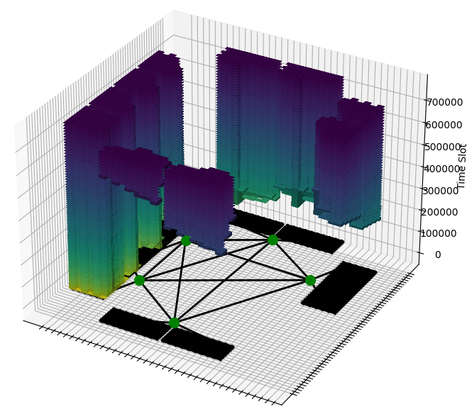
[A 3D graph illustrating a network of switches and the stacked states of end-nodes connected to them]The switches are labeled as S1 to S4 and nodes are represented as planar 3 by 3 square grids. The state of each end-node has stacked along the z-axis, representing the changes over time.
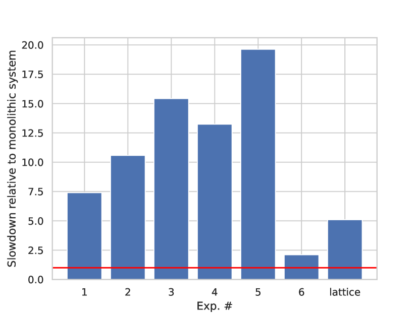
[Execution time comparison bar graph.]Execution time comparison bar graph.
Fig. 11 compares the estimated performance of Q-fly networks shown in Tab. 5. Note that all links have the same quantum communication capacity. Note that because the absolute execution time is technology-dependent, we stick to the relative comparison and renormalize all execution times to the monolithic case. The graph shows that the performance depends largely on the network topology. Experiment #1 shows use of multi-hop routing and effects of contention for inter-group links. Due to the 1.4dB GroupLoss(k=4), round time is 1.3x slower, but with achieved concurrency, overall performance improves. The best case is Experiment #6, consisting of 17 groups, each holding a switch with radix of 16 and 8 end nodes, and each end node holds only one logical data qubit. This setting also gives very high concurrency (up to 40 connections active) and always uses single-hop paths. It is the highest performing configuration but requires the largest number of fibers and switch ports. This pattern is the fastest because the competing resources to execute multiple lattice surgeries in parallel are avoided thanks to the non-blocking switch design, and all CNOT gates can be executed in parallel unless the same logical qubits are used in the CNOT gates simultaneously.
6. Discussion
With our proposed Q-Fly topology now evaluated in light of our prototype network for one of the most important subroutines, we turn our attention to the next steps for deploying Q-Fly in production systems.
The end-to-end performance of our prototype implementation is only a few on average. The losses in Tab. 3 total to (depending on which nodes are to be entangled) and the BSA success probability is . This gives a success rate of less than one in a million against a trial rate of . Another main reason for the low rate is that the SPDC entanglement generation probability is set to for each attempt. Over two hops, that low probability is squared. Employing technology such as cavity enhancement of photon emission from atoms could possibly lead to success probability improvements of an order of magnitude or more; however, this approach lengthens photon emission time and correspondingly reduces the trial rate, so the net effect must be engineered carefully (Krutyanskiy et al., 2023). Another factor decreasing the performance of the network is the switching time to change the state of the group switch. Integrated photonic circuits will be a good option when the state changes of the group switches occur at a high rate.
Another option for building a high-performance link is to use one-photon interference, which suffers photon loss probability along a path where two-photon interference suffers in (Lucamarini et al., 2018). About improvement would be expected in our case, at the cost of far more severe phase stabilization demands on the interferometer; path lengths must be stabilized to much less than the wavelength of the photons, in sharp contrast to the looser requirements for two-photon interference described in Fig. 6.
Sharp-eyed readers may have noted that Fig. 1 uses entangled photon pair sources as part of each end node, but Fig. 3 focuses on computational end nodes that can emit photons entangled with their memories. The best way to use EPPS sources deserves further study, especially with respect to methods of connecting nodes with memory to the network (Soon et al., 2024).
We should also consider the recovery time of SNSPDs. In our case, it is 15 ns (67 MHz). This time is much longer than the repetition rate of the entanglement generation (1 GHz). In our network prototype, it does not matter because of the low success rate of entangled photon generation. If we increase the success rate, it could cause problems. Suppose we have quantum computers at the end nodes with communication qubits that transmit photons. In that case, the reset time of communication qubits and the round-trip time, including photon transmission and herald notification, must be considered. More specifically, given 10-meter links between computational nodes and BSAs, the optical transmission round-trip time, including photon transmission and herald notification, is about 100 ns. Depending on the technology, the communication qubit’s reset time typically ranges from 1 ns to 1 s. Since these factors limit the repetition rate, the SNSPDs’ recovery times will not cause a major problem.a
Here, we have proposed only three variants of the Q-Fly architecture. Further analysis of quantum computing workloads and their traffic patterns is necessary to determine optimal designs for datacenter-scale quantum networks. The relative number and destination of group interconnects, arrangement of BSAs, and composition of end nodes can all be adjusted, and all affect both the performance and construction cost of such networks. This flexibility makes Dragonfly-based designs such as Q-Fly a promising framework for exploring and addressing future computational needs.
7. Conclusion
We proposed Q-Fly, a quantum interconnect for high-performance connectivity for distributed quantum computation, and evaluated our implementation of many of the elements of a full interconnect stack, from the physical level through compiling distributed programs. We developed and demonstrated an elementary building block of the Q-Fly network, composed of three optical end nodes and an optical quantum switch node, integrating quantum and classical hardware and software. We evaluated the performance of the Q-Fly network with a distributed quantum computing performance evaluation tool developed for this work with a QFT circuit. Our simulation model is designed with the loss-based transmittance of practical 22 switches. We discussed the applicability of our demonstrated network to actual distributed quantum computation with end nodes with stationary qubits.
Based on the findings we have elucidated in this study, more advanced systems and their architectures can be designed: memory-equipped quantum network systems, interoperable systems of memoryless and memory-equipped quantum networks, and multiplexed networks, which must contribute to generating Bell pairs in the time required for remote stabilizer measurement for fault-tolerant quantum computation.
The goal of this work is far more ambitious than just demonstration of a one-off prototype. We expect portions of our technology to be used in development of much larger, production systems, and to serve as a basis for continued evolution. Even more importantly, we intend for the protocols and network architecture be standardized (Kozlowski et al., 2023), much as the interconnects for classical supercomputers are, and are working toward publication of specifications that will advance interoperability and the development of commercial products.
Acknowledgments
This work was supported by JST [Moonshot R&D Program] Grant Number [JPMJMS226C] (all authors), and Grant Numbers [JPMJMS2066] (RI) and [JPMJMS2061] (RDV). YU thanks the RIKEN Special Postdoctoral Researcher Program. The authors thank Takao Tomono, Masahiro Takeoka, Tomoyuki Horikiri, Teruo Tanimoto, and Yuya Kawakami for technical advice and student support; Kent Oonishi, Kaori Nogata, Kaori Sugihara, Saori Sato and junsec for logistical support; and the many members of QITF, the Nagayama Moonshot, AQUA, and WIDE for technical collaborations and support.
Availability
Specifications for many of the classical control protocols and designs will be published as Creative Commons-licensed documents.
References
- (1)
- Ahsan et al. (2015) Muhammad Ahsan, Rodney Van Meter, and Jungsang Kim. 2015. Designing a Million-Qubit Quantum Computer Using a Resource Performance Simulator. J. Emerg. Technol. Comput. Syst. 12, 4, Article 39 (Dec. 2015), 25 pages. https://doi.org/10.1145/2830570
- Ajima et al. (2009) Yuichiro Ajima, Shinji Sumimoto, and Toshiyuki Shimizu. 2009. Tofu: A 6D Mesh/Torus Interconnect for Exascale Computers. Computer 42 (2009), 36–40. https://doi.org/10.1109/MC.2009.370
- Alshowkan et al. (2022) Muneer Alshowkan, Philip G. Evans, Brian P. Williams, Nageswara S. V. Rao, Claire E. Marvinney, Yun-Yi Pai, Benjamin J. Lawrie, Nicholas A. Peters, and Joseph M. Lukens. 2022. Advanced architectures for high-performance quantum networking. J. Opt. Commun. Netw. 14, 6 (Jun 2022), 493–499. https://doi.org/10.1364/JOCN.450201
- Alshowkan et al. (2021) Muneer Alshowkan, Brian P. Williams, Philip G. Evans, Nageswara S.V. Rao, Emma M. Simmerman, Hsuan-Hao Lu, Navin B. Lingaraju, Andrew M. Weiner, Claire E. Marvinney, Yun-Yi Pai, Benjamin J. Lawrie, Nicholas A. Peters, and Joseph M. Lukens. 2021. Reconfigurable Quantum Local Area Network Over Deployed Fiber. PRX Quantum 2 (Oct 2021), 040304. Issue 4. https://doi.org/10.1103/PRXQuantum.2.040304
- Ang et al. (2024) James Ang, Gabriella Carini, Yanzhu Chen, Isaac Chuang, Michael DeMarco, Sophia Economou, Alec Eickbusch, Andrei Faraon, Kai-Mei Fu, Steven Girvin, Michael Hatridge, Andrew Houck, Paul Hilaire, Kevin Krsulich, Ang Li, Chenxu Liu, Yuan Liu, Margaret Martonosi, David McKay, Jim Misewich, Mark Ritter, Robert Schoelkopf, Samuel Stein, Sara Sussman, Hong Tang, Wei Tang, teague tomesh, Norm Tubman, Chen Wang, Nathan Wiebe, Yongxin Yao, Dillon Yost, and Yiyu Zhou. 2024. ARQUIN: Architectures for Multinode Superconducting Quantum Computers. ACM Transactions on Quantum Computing 5, 3 (Sep 2024), 1–59. https://doi.org/10.1145/3674151
- Arute et al. (2019) Frank Arute, Kunal Arya, Ryan Babbush, Dave Bacon, Joseph C Bardin, Rami Barends, Rupak Biswas, Sergio Boixo, Fernando GSL Brandao, David A Buell, et al. 2019. Quantum supremacy using a programmable superconducting processor. Nature 574, 7779 (2019), 505–510.
- Athas and Seitz (1988) William C. Athas and Charles L. Seitz. 1988. Multicomputers: message-passing concurrent computers. IEEE Computer 21 (Aug. 1988), 9–24.
- Awschalom et al. (2021) David Awschalom, Karl K. Berggren, Hannes Bernien, Sunil Bhave, Lincoln D. Carr, Paul Davids, Sophia E. Economou, Dirk Englund, Andrei Faraon, Martin Fejer, Saikat Guha, Martin V. Gustafsson, Evelyn Hu, Liang Jiang, Jungsang Kim, Boris Korzh, Prem Kumar, Paul G. Kwiat, Marko Lončar, Mikhail D. Lukin, David A.B. Miller, Christopher Monroe, Sae Woo Nam, Prineha Narang, Jason S. Orcutt, Michael G. Raymer, Amir H. Safavi-Naeini, Maria Spiropulu, Kartik Srinivasan, Shuo Sun, Jelena Vučković, Edo Waks, Ronald Walsworth, Andrew M. Weiner, and Zheshen Zhang. 2021. Development of Quantum Interconnects (QuICs) for Next-Generation Information Technologies. PRX Quantum 2 (Feb 2021), 017002. Issue 1. https://doi.org/10.1103/PRXQuantum.2.017002
- Azuma et al. (2023) Koji Azuma, Sophia E. Economou, David Elkouss, Paul Hilaire, Liang Jiang, Hoi-Kwong Lo, and Ilan Tzitrin. 2023. Quantum repeaters: From quantum networks to the quantum internet. Rev. Mod. Phys. 95 (2023), 045006. https://doi.org/10.1103/RevModPhys.95.045006
- Barral et al. (2024) David Barral, F Javier Cardama, Guillermo Díaz, Daniel Faílde, Iago F Llovo, Mariamo Mussa Juane, Jorge Vázquez-Pérez, Juan Villasuso, César Piñeiro, Natalia Costas, et al. 2024. Review of distributed quantum computing. from single qpu to high performance quantum computing. arXiv preprint arXiv:2404.01265 (2024).
- Bennett et al. (1993a) Charles H. Bennett, Gilles Brassard, Claude Crépeau, Richard Jozsa, Asher Peres, and William K. Wootters. 1993a. Teleporting an unknown quantum state via dual classical and Einstein-Podolsky-Rosen channels. Physical Review Letters 70, 13 (3 1993), 1895. https://doi.org/10.1103/PhysRevLett.70.1895
- Bennett et al. (1993b) Charles H. Bennett, Gilles Brassard, Claude Crépeau, Richard Jozsa, Asher Peres, and William K. Wootters. 1993b. Teleporting an unknown quantum state via dual classical and Einstein-Podolsky-Rosen channels. Phys. Rev. Lett. 70 (Mar 1993), 1895–1899. Issue 13. https://doi.org/10.1103/PhysRevLett.70.1895
- Besta and Hoefler (2014) Maciej Besta and Torsten Hoefler. 2014. Slim Fly: A Cost Effective Low-Diameter Network Topology. In SC ’14: Proceedings of the International Conference for High Performance Computing, Networking, Storage and Analysis. IEEE, New Orleans, LA, USA, 348–359. https://doi.org/10.1109/SC.2014.34
- Briegel et al. (1998) H.-J. Briegel, W Dür, J I Cirac, and P Zoller. 1998. Quantum Repeaters: The Role of Imperfect Local Operations in Quantum Communication. Physical Review Letters 81, 26 (12 1998), 5932–5935. https://doi.org/10.1103/PhysRevLett.81.5932
- Caleffi et al. (2024) Marcello Caleffi, Michele Amoretti, Davide Ferrari, Jessica Illiano, Antonio Manzalini, and Angela Sara Cacciapuoti. 2024. Distributed quantum computing: a survey. Computer Networks 254 (2024), 110672.
- Calient (2024) Calient. (accessed: 18.11.2024). . CALIENT Technologies. https://www.calient.net/
- Dally and Towles (2004) William James Dally and Brian Towles. 2004. Principles and Practices of Interconnection Networks. Elsevier, San Francisco, CA, USA.
- de Bone et al. (2024) Sébastian de Bone, Paul Möller, Conor E. Bradley, Tim H. Taminiau, and David Elkouss. 2024. Thresholds for the distributed surface code in the presence of memory decoherence. AVS Quantum Science 6, 3 (July 2024), 033801. https://doi.org/10.1116/5.0200190 _eprint: https://pubs.aip.org/avs/aqs/article-pdf/doi/10.1116/5.0200190/20024398/033801_1_5.0200190.pdf.
- De Sensi et al. (2020) Daniele De Sensi, Salvatore Di Girolamo, Kim H McMahon, Duncan Roweth, and Torsten Hoefler. 2020. An in-depth analysis of the slingshot interconnect. In SC20: International Conference for High Performance Computing, Networking, Storage and Analysis. IEEE, IEEE, Atlanta, GA, USA, 1–14.
- Devitt et al. (2013) Simon J. Devitt, Kae Nemoto, William J. Munro, and Kae Nemoto. 2013. Quantum Error Correction for Beginners. Reports on Progress in Physics 76, 7 (6 2013), 076001. https://doi.org/10.1088/0034-4885/76/7/076001
- Dong et al. (2022) Mark Dong, Genevieve Clark, Andrew J Leenheer, Matthew Zimmermann, Daniel Dominguez, Adrian J Menssen, David Heim, Gerald Gilbert, Dirk Englund, and Matt Eichenfield. 2022. High-speed programmable photonic circuits in a cryogenically compatible, visible–near-infrared 200 mm CMOS architecture. Nature Photonics 16, 1 (2022), 59–65.
- Dupuis et al. (2020) Nicolas Dupuis, Jonathan E Proesel, Nicolas Boyer, Herschel Ainspan, Christian W Baks, Fuad Doany, Elaine Cyr, and Benjamin G Lee. 2020. An 8 8 silicon photonic switch module with nanosecond-scale reconfigurability. In 2020 Optical Fiber Communications Conference and Exhibition (OFC). IEEE, San Diego, CA, USA, 1–3.
- Dür and Briegel (2007) Wolfgang Dür and Hans J Briegel. 2007. Entanglement purification and quantum error correction. Reports on Progress in Physics 70, 8 (2007), 1381.
- Eisert et al. (2000) J. Eisert, K. Jacobs, P. Papadopoulos, and M. B. Plenio. 2000. Optimal local implementation of nonlocal quantum gates. Phys. Rev. A 62 (Oct 2000), 052317. Issue 5. https://doi.org/10.1103/PhysRevA.62.052317
- Ekert (1991) Artur K. Ekert. 1991. Quantum cryptography based on Bell’s theorem. Phys. Rev. Lett. 67 (Aug 1991), 661–663. Issue 6. https://doi.org/10.1103/PhysRevLett.67.661
- Fowler et al. (2012) Austin G. Fowler, Matteo Mariantoni, John M. Martinis, and Andrew N. Cleland. 2012. Surface codes: Towards practical large-scale quantum computation. Phys. Rev. A 86 (Sep 2012), 032324. Issue 3. https://doi.org/10.1103/PhysRevA.86.032324
- Fowler et al. (2009) Austin G Fowler, Ashley M Stephens, and Peter Groszkowski. 2009. High-threshold universal quantum computation on the surface code. Physical Review A—Atomic, Molecular, and Optical Physics 80, 5 (2009), 052312.
- Gidney et al. (2024) Craig Gidney, Noah Shutty, and Cody Jones. 2024. Magic state cultivation: growing T states as cheap as CNOT gates. arXiv:2409.17595 [quant-ph] https://arxiv.org/abs/2409.17595
- Gottesman et al. (2012) Daniel Gottesman, Thomas Jennewein, and Sarah Croke. 2012. Longer-Baseline Telescopes Using Quantum Repeaters. Phys. Rev. Lett. 109 (Aug 2012), 070503. Issue 7. https://doi.org/10.1103/PhysRevLett.109.070503
- Guinn et al. (2023) Charles Guinn, Samuel Stein, Esin Tureci, Guus Avis, Chenxu Liu, Stefan Krastanov, Andrew A. Houck, and Ang Li. 2023. Co-Designed Superconducting Architecture for Lattice Surgery of Surface Codes with Quantum Interface Routing Card. arXiv:2312.01246 [quant-ph] https://arxiv.org/abs/2312.01246
- Hong et al. (1987) C. K. Hong, Z. Y. Ou, and L. Mandel. 1987. Measurement of subpicosecond time intervals between two photons by interference. Phys. Rev. Lett. 59 (Nov 1987), 2044–2046. Issue 18. https://doi.org/10.1103/PhysRevLett.59.2044
- Horodecki et al. (2009) Ryszard Horodecki, Paweł Horodecki, Michał Horodecki, and Karol Horodecki. 2009. Quantum entanglement. Rev. Mod. Phys. 81 (Jun 2009), 865–942. Issue 2. https://doi.org/10.1103/RevModPhys.81.865
- Horsman et al. (2012) Dominic Horsman, Austin G Fowler, Simon Devitt, and Rodney Van Meter. 2012. Surface code quantum computing by lattice surgery. New Journal of Physics 14, 12 (2012), 123011.
- IBM (2024) IBM. (accessed: 22.11.2024). Expanding the IBM Quantum roadmap to anticipate the future of quantum-centric supercomputing (Updated 2024). IBM. https://www.ibm.com/quantum/blog/ibm-quantum-roadmap-2025
- Inc. (2024) Polatis Inc. (accessed: 18.11.2024). All SDN Optical Switches. HUBER+SUHNER Polatis. https://www.polatis.com/
- Isailovic et al. (2006) Nemanja Isailovic, Yatish Patel, Mark Whitney, and John Kubiatowicz. 2006. Interconnection Networks for Scalable Quantum Computers. In Proceedings of the 33rd Annual International Symposium on Computer Architecture (ISCA ’06). IEEE Computer Society, USA, 366–377. https://doi.org/10.1109/ISCA.2006.24
- James et al. (2001) Daniel F. V. James, Paul G. Kwiat, William J. Munro, and Andrew G. White. 2001. Measurement of qubits. Phys. Rev. A 64 (Oct 2001), 052312. Issue 5. https://doi.org/10.1103/PhysRevA.64.052312
- Jiang et al. (2007) Liang Jiang, Jacob M. Taylor, Anders S. Sørensen, and Mikhail D. Lukin. 2007. Distributed quantum computation based on small quantum registers. Phys. Rev. A 76 (Dec 2007), 062323. Issue 6. https://doi.org/10.1103/PhysRevA.76.062323
- Jordan et al. (2024) Stephen P Jordan, Noah Shutty, Mary Wootters, Adam Zalcman, Alexander Schmidhuber, Robbie King, Sergei V Isakov, and Ryan Babbush. 2024. Optimization by Decoded Quantum Interferometry. (2024). https://doi.org/10.48550/arXiv.2408.08292
- Kaman et al. (2007) Volkan Kaman, Roger J Helkey, and John E Bowers. 2007. Compact and scalable three-dimensional microelectromechanical system optical switches. Journal of Optical Networking 6, 1 (2007), 19–24.
- Kewitsch (2009) Anthony S Kewitsch. 2009. Large scale, all-fiber optical cross-connect switches for automated patch-panels. Journal of Lightwave Technology 27, 15 (2009), 3107–3115.
- Kim et al. (2003) J. Kim et al. 2003. 1100x1100 Port MEMS-Based Optical Crossconnect with 4-dB Maximum Loss. IEEE Photonics Technology Letters 15, 11 (2003), 1537–1539.
- Kim et al. (2008) John Kim, Wiliam J Dally, Steve Scott, and Dennis Abts. 2008. Technology-driven, highly-scalable dragonfly topology. ACM SIGARCH Computer Architecture News 36, 3 (2008), 77–88.
- Kozlowski et al. (2023) Wojciech Kozlowski, Stephanie Wehner, Rodney Van Meter, Bruno Rijsman, Angela Sara Cacciapuoti, Marcello Caleffi, and Shota Nagayama. 2023. Architectural Principles for a Quantum Internet. RFC 9340. https://doi.org/10.17487/RFC9340
- Krutyanskiy et al. (2023) V. Krutyanskiy, M. Galli, V. Krcmarsky, S. Baier, D. A. Fioretto, Y. Pu, A. Mazloom, P. Sekatski, M. Canteri, M. Teller, J. Schupp, J. Bate, M. Meraner, N. Sangouard, B. P. Lanyon, and T. E. Northup. 2023. Entanglement of Trapped-Ion Qubits Separated by 230 Meters. Phys. Rev. Lett. 130 (Feb 2023), 050803. Issue 5. https://doi.org/10.1103/PhysRevLett.130.050803
- Lakhotia et al. (2022) Kartik Lakhotia, Maciej Besta, Laura Monroe, Kelly Isham, Patrick Iff, Torsten Hoefler, and Fabrizio Petrini. 2022. PolarFly: A Cost-Effective and Flexible Low-Diameter Topology. In SC22: International Conference for High Performance Computing, Networking, Storage and Analysis. IEEE, Dallas, TX, USA, 1–15. https://doi.org/10.1109/SC41404.2022.00017
- Leiserson (1985) Charles E. Leiserson. 1985. Fat-trees: Universal networks for hardware-efficient supercomputing. IEEE Trans. Comput. C-34, 10 (1985), 892–901. https://doi.org/10.1109/TC.1985.6312192
- Leiserson et al. (1992) Charles E. Leiserson, Zahi S. Abuhamdeh, David C. Douglas, Carl R. Feynman, Mahesh N. Ganmukhi, Jeffrey V. Hill, Daniel Hillis, Bradley C. Kuszmaul, Margaret A. St. Pierre, David S. Wells, Monica C. Wong, Shaw-Wen Yang, and Robert Zak. 1992. The network architecture of the Connection Machine CM-5 (extended abstract). In Proceedings of the Fourth Annual ACM Symposium on Parallel Algorithms and Architectures (San Diego, California, USA) (SPAA ’92). Association for Computing Machinery, New York, NY, USA, 272–285. https://doi.org/10.1145/140901.141883
- Leone et al. (2024) Hudson Leone, Thinh Le, S. Srikara, and Simon Devitt. 2024. Resource overheads and attainable rates for trapped-ion lattice surgery. arXiv:2406.18764 [quant-ph] https://arxiv.org/abs/2406.18764
- Litinski (2019) Daniel Litinski. 2019. A Game of Surface Codes: Large-Scale Quantum Computing with Lattice Surgery. Quantum 3 (March 2019), 128. https://doi.org/10.22331/q-2019-03-05-128
- Liu et al. (2023b) Hong Liu, Ryohei Urata, Kevin Yasumura, Xiang Zhou, Roy Bannon, Jill Berger, Pedram Dashti, Norm Jouppi, Cedric Lam, Sheng Li, Erji Mao, Daniel Nelson, George Papen, Mukarram Tariq, and Amin Vahdat. 2023b. Lightwave Fabrics: At-Scale Optical Circuit Switching for Datacenter and Machine Learning Systems. In Proceedings of the ACM SIGCOMM 2023 Conference (New York, NY, USA) (ACM SIGCOMM ’23). Association for Computing Machinery, New York, NY, USA, 499–515. https://doi.org/10.1145/3603269.3604836
- Liu et al. (2023a) Sitong Liu, Naphan Benchasattabuse, Darcy QC Morgan, Michal Hajdušek, Simon J. Devitt, and Rodney Van Meter. 2023a. A Substrate Scheduler for Compiling Arbitrary Fault-Tolerant Graph States. In 2023 IEEE International Conference on Quantum Computing and Engineering (QCE), Vol. 01. IEEE, Bellevue, WA, USA, 870–880. https://doi.org/10.1109/QCE57702.2023.00101
- Lucamarini et al. (2018) Marco Lucamarini, Zhiliang L Yuan, James F Dynes, and Andrew J Shields. 2018. Overcoming the rate–distance limit of quantum key distribution without quantum repeaters. Nature 557, 7705 (2018), 400–403.
- Min et al. (2023) Dongmoon Min, Junpyo Kim, Junhyuk Choi, Ilkwon Byun, Masamitsu Tanaka, Koji Inoue, and Jangwoo Kim. 2023. QIsim: Architecting 10+K Qubit QC Interfaces Toward Quantum Supremacy. In Proceedings of the 50th Annual International Symposium on Computer Architecture (Orlando, FL, USA) (ISCA ’23). Association for Computing Machinery, New York, NY, USA, Article 1, 16 pages. https://doi.org/10.1145/3579371.3589036
- Murali et al. (2019) Prakash Murali, Norbert Matthias Linke, Margaret Martonosi, Ali Javadi Abhari, Nhung Hong Nguyen, and Cinthia Huerta Alderete. 2019. Full-stack, real-system quantum computer studies: architectural comparisons and design insights. In Proceedings of the 46th International Symposium on Computer Architecture (Phoenix, Arizona) (ISCA ’19). Association for Computing Machinery, New York, NY, USA, 527–540. https://doi.org/10.1145/3307650.3322273
- Nagayama (2017) Shota Nagayama. 2017. Distributed Quantum Computing Utilizing Multiple Codes on Imperfect Hardware. Ph. D. Dissertation. Keio University. https://arxiv.org/abs/1704.02620
- Nagayama et al. (2016) Shota Nagayama, Byung-Soo Choi, Simon Devitt, Shigeya Suzuki, and Rodney Van Meter. 2016. Interoperability in encoded quantum repeater networks. PHYSICAL REVIEW A 93 (2016), 042338. https://doi.org/10.1103/PhysRevA.93.042338
- Nickerson et al. (2014) Naomi H. Nickerson, Joseph F. Fitzsimons, and Simon C. Benjamin. 2014. Freely Scalable Quantum Technologies Using Cells of 5-to-50 Qubits with Very Lossy and Noisy Photonic Links. Phys. Rev. X 4 (Dec 2014), 041041. Issue 4. https://doi.org/10.1103/PhysRevX.4.041041
- Nickerson et al. (2013) Naomi H Nickerson, Ying Li, and Simon C Benjamin. 2013. Topological quantum computing with a very noisy network and local error rates approaching one percent. Nature communications 4 (2013), 1756.
- Oi et al. (2006) Daniel K. L. Oi, Simon J. Devitt, and Lloyd C. L. Hollenberg. 2006. Scalable error correction in distributed ion trap computers. Physical Review A—Atomic, Molecular, and Optical Physics 74 (2006), 052313.
- Pompili et al. (2022) M. Pompili, C. Delle Donne, I. te Raa, B. van der Vecht, M. Skrzypczyk, G. Ferreira, L. de Kluijver, A. J. Stolk, S. L. N. Hermans, P. Pawełczak, W. Kozlowski, R. Hanson, and S. Wehner. 2022. Experimental demonstration of entanglement delivery using a quantum network stack. npj Quantum Information 8, 1 (2022), 121. https://doi.org/10.1038/s41534-022-00631-2
- Preskill (2018) John Preskill. 2018. Quantum Computing in the NISQ era and beyond. Quantum 2 (8 2018), 79. https://doi.org/10.22331/q-2018-08-06-79
- Qiao et al. (2017) Lei Qiao, Weijie Tang, and Tao Chu. 2017. 32 32 silicon electro-optic switch with built-in monitors and balanced-status units. Scientific Reports 7, 1 (2017), 42306.
- Rao et al. (2023) Nageswara S. V. Rao, Muneer Alshowkan, Joseph C. Chapman, Nicholas A. Peters, and Joseph M. Lukens. 2023. Throughput Measurements and Capacity Estimates for Quantum Connections. In IEEE INFOCOM 2023 - IEEE Conference on Computer Communications Workshops (INFOCOM WKSHPS). IEEE, Hoboken, NJ, USA, 1–6. https://doi.org/10.1109/INFOCOMWKSHPS57453.2023.10226117
- Ross and Selinger (2016) Neil J Ross and Peter Selinger. 2016. Optimal ancilla-free Clifford+ T approximation of z-rotations. Quantum Inf. Comput. 16, 11&12 (2016), 901–953.
- Seok et al. (2019) Tae Joon Seok, Kyungmok Kwon, Johannes Henriksson, Jianheng Luo, and Ming C. Wu. 2019. 240×240 Wafer-Scale Silicon Photonic Switches. In Optical Fiber Communication Conference (OFC) 2019. Optica Publishing Group, San Diego, California, USA, Th1E.5. https://doi.org/10.1364/OFC.2019.Th1E.5
- Seok et al. (2016) Tae Joon Seok, Niels Quack, Sangyoon Han, Richard S Muller, and Ming C Wu. 2016. Large-scale broadband digital silicon photonic switches with vertical adiabatic couplers. Optica 3, 1 (2016), 64–70.
- Shor (1997) Peter W. Shor. 1997. Polynomial-time algorithms for prime factorization and discrete logarithms on a quantum computer. SIAM J. Comput. 26, 5 (1997), 1484–1509. https://doi.org/10.1137/S0097539795293172
- Shpiner et al. (2017) Alexander Shpiner, Zachy Haramaty, Saar Eliad, Vladimir Zdornov, Barak Gafni, and Eitan Zahavi. 2017. Dragonfly+: Low Cost Topology for Scaling Datacenters. In 2017 IEEE 3rd International Workshop on High-Performance Interconnection Networks in the Exascale and Big-Data Era (HiPINEB). IEEE, Austin, TX, USA, 1–8. https://doi.org/10.1109/HiPINEB.2017.11
- Soon et al. (2024) Kento Samuel Soon, Michal Hajdušek, Shota Nagayama, Naphan Benchasattabuse, Kentaro Teramoto, Ryosuke Satoh, and Rodney Van Meter. 2024. An Implementation and Analysis of a Practical Quantum Link Architecture Utilizing Entangled Photon Sources. arXiv:2405.09861 [quant-ph] https://arxiv.org/abs/2405.09861
- Spanke and Benes (1987) R. A. Spanke and V. E. Benes. 1987. N-stage planar optical permutation network. Appl. Opt. 26, 7 (Apr 1987), 1226–1229. https://doi.org/10.1364/AO.26.001226
- Steffen et al. (2011) M. Steffen, D. P. DiVincenzo, J. M. Chow, T. N. Theis, and M. B. Ketchen. 2011. Quantum computing: An IBM perspective. IBM Journal of Research and Development 55, 5 (2011), 13:1–13:11. https://doi.org/10.1147/JRD.2011.2165678
- Stunkel et al. (2020) C. B. Stunkel, R. L. Graham, G. Shainer, M. Kagan, S. S. Sharkawi, B. Rosenburg, and G. A. Chochia. 2020. The high-speed networks of the Summit and Sierra supercomputers. IBM Journal of Research and Development 64, 3/4 (2020), 3:1–3:10. https://doi.org/10.1147/JRD.2020.2967330
- Suzuki et al. (2014) Keijiro Suzuki, Ken Tanizawa, Takashi Matsukawa, Guangwei Cong, Sang-Hun Kim, Satoshi Suda, Morifumi Ohno, Tadashi Chiba, Hirofumi Tadokoro, Masashi Yanagihara, et al. 2014. Ultra-compact 8 8 strictly-non-blocking Si-wire PILOSS switch. Optics Express 22, 4 (2014), 3887–3894.
- Tan et al. (2024) Daniel Bochen Tan, Murphy Yuezhen Niu, and Craig Gidney. 2024. A SAT Scalpel for Lattice Surgery: Representation and Synthesis of Subroutines for Surface-Code Fault-Tolerant Quantum Computing . In 2024 ACM/IEEE 51st Annual International Symposium on Computer Architecture (ISCA). IEEE Computer Society, Los Alamitos, CA, USA, 325–339. https://doi.org/10.1109/ISCA59077.2024.00032
- Tanizawa et al. (2015) Ken Tanizawa, Keijiro Suzuki, Munehiro Toyama, Minoru Ohtsuka, Nobuyuki Yokoyama, Kazuyuki Matsumaro, Miyoshi Seki, Keiji Koshino, Toshio Sugaya, Satoshi Suda, et al. 2015. Ultra-compact 32 32 strictly-non-blocking Si-wire optical switch with fan-out LGA interposer. Optics express 23, 13 (2015), 17599–17606.
- Telescent (2024) Telescent. (accessed: 18.11.2024). https://www.telescent.com/products
- Vaidman and Yoran (1999) Lev Vaidman and Nadav Yoran. 1999. Methods for reliable teleportation. Phys. Rev. A 59 (Jan 1999), 116–125. Issue 1. https://doi.org/10.1103/PhysRevA.59.116
- Van Meter (2014) Rodney Van Meter. 2014. Quantum networking. John Wiley & Sons, Hoboken, NJ, USA.
- Van Meter and Devitt (2016) Rodney Van Meter and Simon Devitt. 2016. The Path to Scalable Distributed Quantum Computing. IEEE Computer 49, 9 (Sept. 2016), 31–42. https://doi.org/10.1109/MC.2016.291
- Van Meter et al. (2010) Rodney Van Meter, Thaddeus D. Ladd, Austin G. Fowler, and Yoshihisa Yamamoto. 2010. Distributed Quantum Computation Architecture Using Semiconductor Nanophotonics. International Journal of Quantum Information 8 (2010), 295–323. https://www.worldscientific.com/doi/abs/10.1142/S0219749910006435
- Van Meter et al. (2008) Rodney Van Meter, W. J. Munro, Kae Nemoto, and Kohei M. Itoh. 2008. Arithmetic on a Distributed-Memory Quantum Multicomputer. Journal of Emerging Technologies in Computing Systems 3, 4 (Jan. 2008), 17. https://doi.org/10.1145/1324177.1324179
- Van Meter III (2006) Rodney Doyle Van Meter III. 2006. Architecture of a Quantum Multicomputer Optimized for Shor’s Factoring Algorithm. Ph. D. Dissertation. Keio University. available as arXiv:quant-ph/0607065.
- Wootters and Zurek (1982) W. K. Wootters and W. H. Zurek. 1982. A single quantum cannot be cloned. Nature 299, 5886 (1982), 802–803. https://doi.org/10.1038/299802a0
- Yang et al. (2010) Min Yang, William MJ Green, Solomon Assefa, Joris Van Campenhout, Benjamin G Lee, Christopher V Jahnes, Fuad E Doany, Clint L Schow, Jeffrey A Kash, and Yurii A Vlasov. 2010. Non-blocking 4x4 electro-optic silicon switch for on-chip photonic networks. Optics express 19, 1 (2010), 47–54.
- Yoshioka et al. (2024) Nobuyuki Yoshioka, Tsuyoshi Okubo, Yasunari Suzuki, Yuki Koizumi, and Wataru Mizukami. 2024. Hunting for quantum-classical crossover in condensed matter problems. npj Quantum Information 10, 1 (2024), 45.