Bullet pressure-cell design for neutron scattering experiments with horizontal magnetic fields and dilution temperatures
Abstract
The simultaneous application of high magnetic fields and high pressures for controlling magnetic ground states is important for testing our understanding of many-body quantum theory. However, the implementation for neutron scattering experiments presents a technical challenge. To overcome this challenge we present an optimized pressure-cell design with a novel bullet shape, which is compatible with horizontal-field magnets, in particular the high-field magnet operating at the Helmholtz-Zentrum Berlin. The cell enabled neutron diffraction and spectroscopy measurements with the combination of three extreme conditions: high pressures, high magnetic fields, and dilution temperatures, simultaneously reaching , , and . Our results demonstrate the utility of informed material choices and the efficiency of finite-element analysis for future pressure-cell designs to be used in combination with magnetic fields and dilution temperatures for neutron scattering purposes.
I Introduction
To map out phase diagrams and to characterize critical behavior close to quantum phase transitions it is essential to be able to control applied magnetic fields, hydrostatic pressures and temperatures simultaneously during an experiment. The Zeeman term in the spin Hamiltonian is exact and the magnetic field strength may be tuned accurately in situ. Hydrostatic pressure is a means of manipulating interatomic bond lengths and angles and thereby alter magnetic interactions while preserving the chemical composition. Many quantum magnets require low temperatures to reach the interesting part of their phase diagrams Sachdev (2000); Vasiliev et al. (2018). Finally, neutron scattering is a unique technique for studying spin correlations directly Boothroyd (2020) and because neutrons penetrate matter easily compared to other scattering probes, such as X-rays or electrons, it is possible to have large equipment for controlling the sample environment. Therefore, neutron scattering experiments for studying quantum magnetic systems under applied magnetic field and pressures and at low temperatures constitute an extremely powerful tool.
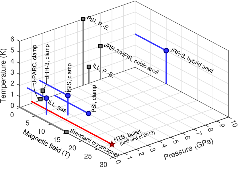
| Facility | Cell type | Pressure (GPa) | Magnetic field (T) | Temperature (K) | Sample space (mm3) |
|---|---|---|---|---|---|
| ISIS Goodway and Kirichek ; Neutron and Source (2022) | Clamp | 1.75 | 9 | 1.8 | Ø |
| ILL Laue-Langevin (2022) | P.-E. | 6.0 | – | 1.5 | Ø |
| Gas | 0.7 | 6 | 1.5 | Ø | |
| PSI Khasanov et al. (2022); Institute (2022) | Clamp | 3.0 | 11 | 0.020 | Ø |
| P.-E. | 5.5 | – | 6 | Ø | |
| JRR-3 Aso et al. (2007); Kaneko et al. (2024); Osakabe et al. (2010) | Clamp | 2.0 | – | 0.8 | Ø |
| Hybrid anvil | 10 | 10 | 3 | Ø | |
| JRR-3 / HFIR Dissanayake et al. (2019) | Cubic anvil | 7.0 | – | 3 | |
| J-PARC (Komatsua et al., 2015) | Clamp | 1.8 | – | 0.1 | Ø |
| HZB (until end of 2019) | Bullet | 1.0 | 25.9 | 0.200 | Ø |
An overview of capabilities at different neutron scattering facilities is presented in Table 1 and illustrated in Fig. 1. A combination of a dilution refrigerator and a standard vertical superconducting cryomagnet provides routinely and , which gives access to the phase diagram of many systems. Until the end of 2019 a High Field Magnet (HFM) facility for neutron scatttering was operated at the Extreme Environment Diffractometer (EXED) at the Helmholtz-Zentrum Berlin (HZB) Prokhnenko et al. (2015); Smeibidl et al. (2016); Prokhnenko et al. (2016, 2017). The hybrid magnet consisted of a resistive and a superconducting coil, which together with a bespoke dilution refigerator, built in collaboration with the University of Birmingham, provided field strengths up to and temperatures down to at the sample position. However, combining low temperatures with applied pressures is more challenging because of the power required to cool the pressure cell, which is typically a large piece of metal. This has been achieved and documented in literature down to for pressures up to Kozlenko et al. (2008); Rüegg et al. (2008), down to for pressures up to Terada et al. (2020); Fogh et al. (2024a), and down to for pressures up to Klotz et al. (2016), depending on the type of pressure cell and the type of measurement. Neutron scattering studies with high pressures and temperatures below remain very few and to our best knowledge there have to date been no reports of combining all three extremes: High pressures (), high magnetic fields () and low temperatures ().
In this paper, we present a piston-cylinder pressure cell compatible with the dilution insert of the unique HFM/EXED instrument at the HZB. With an ultra-compact-cell design and optimized material choices, we succeeded in performing an inelastic neutron scattering experiment at , , and , and in this way probing spin excitations under these extreme conditions. The novel bullet design, meaning with a dome shape on the outgoing neutron beam side, allows the scattered signal to escape in a wide range of angles. The concept opens an alternative path to explore for future pressure-cell engineering for neutron scattering purposes, in particular in combination with horizontal magnetic fields.
II Overview of apparatus
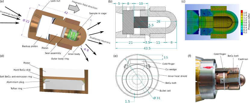
The horizontal geometry and limited sample space of the magnet called for a highly specialized pressure-cell design. We used finite-element analysis as implemented in the software package ANSYS to simulate the pressure inside the cell and the strain on the components in order to optimize dimensions and material choices. The aim was to minimize the neutron background and attenuation, as well as to maximize the sample volume while obtaining at the sample position. Existing piston-cylinder cells typically consist of a vertical double-walled cylinder with pistons pushing from both top and bottom. In such cells, the neutrons travel through the cylinder walls in the transverse direction and not through the pistons. In the case of the spacially limited horizontal HFM, the neutrons were instead required to travel along the length of the cylinder. To minimize the neutron beam path through the pistons, we proposed a design consisting of a single piston assembly in the incoming beam path and a dome-shaped single wall at the other end. Due to this shape, it was named the ”bullet” cell. A 3-dimensional (3D) representation and technical drawing of the bullet cell are shown in Fig. 2(a)-(b) and a color contour representation of the pressure distribution is shown in Fig. 2(c).
The outer diameter of the cell is with a sample space diameter of . The sample space height is around and the total length of the cell around when closed. The exact dimensions when loaded depend on the piston displacement. The body of the cell is a double wall of hardened BeCu with the outer support ring shink fitted in place. The dome-shaped part of the cell consists of a single wall, which allows more neutrons to escape when scattered from the sample compared to a double wall. This shape also provides an optimal force distribution, such that a single wall can support the required pressure. On the incoming-beam side, the locknut has a conical opening to allow rotation of the cell with respect to the incoming neutron beam. Ceramic ZrO2 (Coorstek Technox 3000) is the material choice for the piston in order to minimize the absorption of incoming neutrons when they travel through the piston to reach the sample. The ceramic is more transparent to neutrons than, for example, tungsten carbide, but it is brittle compared to metallic BeCu. Therefore the piston is the limiting part in this design with regards to the maximum achievable pressure.
The seal assembly [Fig. 2(d)] consists of four parts: a teflon ring, an aluminum plug, a soft BeCu anti-extrusion ring and a hardened BeCu disk. The assembly seals directly against the wall of the bore and no sample can is required. Because of this design it is necessary to polish the bore inside prior to loading in order to remove any scratches that may cause leaks. This was performed using a lathe and SiC grinding paper down to Grit 4000 (US #1200) and then diamond paste down to a grain size of . This procedure was repeated for each loading, which means that the bore gets slightly wider for each load and will eventually be too wide to be used with the same seal assembly and pistons. The anti-extrusion ring was covered with indium to create the initial seal. The BeCu disk inserted at the end serves to prevent the ceramic pistons from cracking by mediating the force more evenly over the surface. The disk is slightly dome shaped.
All parts of the pressure cell, seal assembly and pistons were cleaned carefully using acetone and an ultrasound bath prior to loading. Afterwards, the sample was placed in the bore. The seal assembly was then prepared by squeezing the anti-extrusion ring with on a hydraulic press using a steel ball with diameter to achieve a slightly tighter fit inside the bore of the cell. The teflon ring was mounted on the aluminum plug. A deuterated 4:1 methanol-ethanol mixture was used as pressure medium and injected with a syringe to prevent air bubbles from becoming trapped under the sample. Deuterated methanol-ethanol was used to avoid the large incoherent neutron scattering associated with hydrogen Sears (1992), which generates an undesired addition to the background. In order to allow sufficient piston displacement for the required pressure while engaging enough thread to sustain the load on the locknut, a pressure-medium level of approximately as measured from the top of the bore was optimal. The seal was then placed by first inserting the aluminum plug with the teflon ring and using a brass plate to push it in evenly. The anti-extrusion ring was placed on top and also pushed in with the brass plate. The BeCu disk was placed in the bore with the top of the dome on the piston side. The assembly was engaged using a tungsten (W720) dummy piston and loaded to for initial sealing. Finally, pressure was applied using the ceramic pistons while making sure that all parts were well centered, ensuring an even load and that the locknut would fit the threads once the desired piston displacement had been reached. Note that to minimize material, the locknut did not reach the thread of the cell body prior to loading. A holder fitted to the dome shape of the bullet cell body allowed us to carry out the loading on a standard hydraulic press. The load was increased slowly and continuously. Once the maximum load of was reached the cell was monitored for approximately to ensure that all components stayed in place and no leaks appeared. The locknut was tightened 3 times to , with the load topped up to between each tightening. The duration of the press release was similar to the loading process while keeping track of the piston displacement in both directions. The loaded cell had a total mass of approximately .
The cell was mounted on the cold finger of the dilution refrigerator for the HFM by using a BeCu belt of thickness , as shown in Figs. 2(e)-(f). To adapt from the flat surface of the cold finger to the rounded shape of the pressure cell, as well as to ensure thermal contact, a Cu wedge was inserted between the two surfaces. The wedge was gold plated on the curved side. The belt was tightened by engaging screws on either side. Cadmium masks were added on both the incoming and scattered beam sides to reduce the amount of illuminated cell material and to prevent neutrons scattered off the cell from reaching the detector.
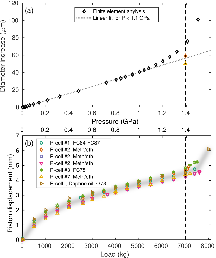
Figure 3(a) shows the simulated diameter increase of the pressure cell as a function of the applied pressure. The curve deviates from linear behavior above around . The corresponding measured piston displacement as a function of applied load is shown for 7 individual loadings in Fig. 3(b). The loading curves are remarkably similar, regardless of the cell number and pressure medium. The linear behavior ends around , which corresponds to at the sample position assuming no friction. Noting that the linear behavior of the piston displacement starts only around , and allowing for some of the applied force being lost to friction, the simulation and experiment can be said to agree with each other. The fact that the loading curve is initially non-linear is explained by air trapped in the system, which has a much higher compressibility compared to the any of the pressure media used in our tests. Beyond a load of , the BeCu deforms plastically. Especially the dome part of the cell with its single wall expands irregularly and does not revert to original size and shape upon depressurization. Note that upon cooling there is a substantial pressure loss of 30-50% (pressure determination at is treated in Section IV). Furthermore, once loaded the pressure was found to be leaking slowly (half life around 10 days with pressure fully lost after a month). This was observed by monitoring the decrease of the cell diameter over time. Consequently one needs to load the cell immediately before the experiment and cool it down without delay. Once the pressure medium is frozen, the pressure is conserved.
III Experiment
The material of choice for testing the bullet pressure-cell design is the quantum magnet SrCu2(BO3)2, which represents a physical realization Miyahara and Ueda (1999) of what is known as the Shastry-Sutherland model (SSM) Shastry and Sutherland (1981). The magnetic lattice consists of pairs of Cu2+ () ions (dimers) arranged orthogonally to all neighboring pairs. The superexchange interactions are within the dimer, and between dimers. At ambient conditions, SrCu2(BO3)2 is well described by the SSM with Miyahara and Ueda (1999); Kageyama et al. (1999a, 2000a, 2000b); Gaulin et al. (2004); Kakurai et al. (2005), and the ground state of the system is a product of singlets on the dimers Koga and Kawakami (2000); Chung et al. (2001); Läuchli et al. (2002); Corboz and Mila (2013); Nakano and Sakai (2018); Xi et al. (2023). Upon applying a magnetic field, a series of magnetization plateaux is observed Onizuka et al. (2000); Takigawa et al. (2013); Matsuda et al. (2013); Shi et al. (2022); Nomura et al. (2023) with the first of these occuring at . Here, the magnetization is 1/8 of its saturation value and a spin superstructure is predicted Corboz and Mila (2014). Torque measurements and numerical calculations indicate that applying pressure to SrCu2(BO3)2 suppresses the transition field, bringing it below Haravifard et al. (2016); Mila and Schmidt (2016); Shi et al. (2022) and thus enabling a neutron scattering study of the magnetization plateau in SrCu2(BO3)2 by using a combination of the bullet cell and the HFM/EXED facility.
The HFM allowed for direct probing of the magnetic structure and dynamics up to static magnetic fields, the bulllet cell provided a hydrostatic pressure of , and the dilution insert took the system to a temperature of . The magnet had conical opening angles, which in combination with magnet rotation of from the incident neutron beam and the time-of-flight (ToF) technique implemented on EXED, gave access to a substantial region in momentum transfer, , and energy transfer, . A schematic representation of the setup is shown in Fig. 4(a). Three different chopper settings produced a wavelength band of Å for diffraction and incoming energies and for inelastic measurements. A general characterization study of the bullet cell was performed by varying the magnet rotation angle. For collecting magnetic diffraction data we chose magnet rotation angle and for inelastic measurements we positioned the magnet at . The latter angle was chosen as a compromise between access to a larger portion of reciprocal space and optimal neutron transmission through the pressure cell. Only forward scattering detectors were used in this experiment.
A single crystal of SrCu2(BO3)2 grown by the floating-zone method Kageyama et al. (1999b); Jorge et al. (2004), was cut with octagonal cross section perpendicular to the -direction. This shape was chosen as a compromise between maximizing the sample volume in the cylindrical sample space and still being practical to cut. The resulting sample had a mass of and was mounted in an aluminum cage as shown in Fig. 2(a). The orientation of the SrCu2(BO3)2 crystal was chosen to optimize the coverage in . Multiple scenarios for sample and magnet orientations were simulated using the software packages EXEQ and InEXEQ, developed specfically for experiment planning at the HFM/EXED facility Bartkowiak et al. (2020). Theoretical calculations predict a spin texture with ordering vector in the -plane for the magnetization plateau Corboz and Mila (2014). To observe this, the -direction of the crystal had to be tilted in the horizontal plane with respect to the magnetic field direction and with an optimal tilt angle of . The resulting sample orientation was determined by tracking nuclear Bragg peak positions on the detector upon magnet rotation.
IV Results
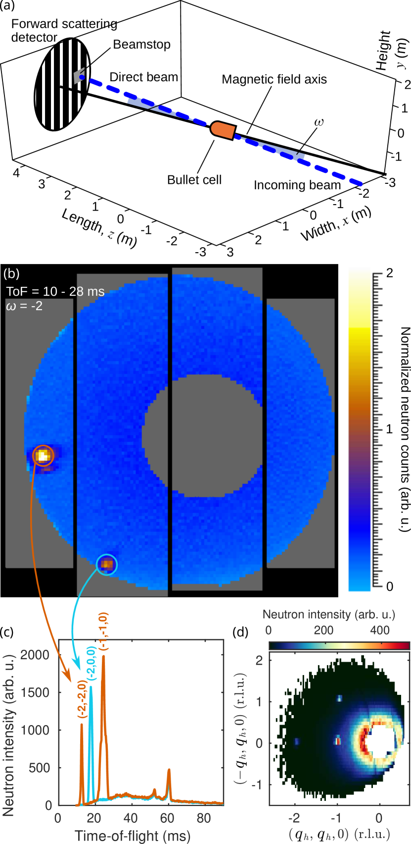
We start by examining the characterization results with a representative zero-field detector image shown in Fig. 4(b). The corresponding ToF intensity profiles for the observed nuclear Bragg peaks and reciprocal coverage are shown in Fig. 4(c)-(d). All nuclear signals were observed for flight times below . At larger flight times, around and , two additional peaks were observed. These are of spurious origin, as we demonstrate further below. To estimate the overall signal-to-noise performance of the bullet cell we did the following for each magnet rotation angle: (i) the Bragg peak intensities were determined by numerical integration over the relevant detector pixels and ToF intervals like in Fig. 4(b)-(c), (ii) the background signals were estimatated by integrating parts of the detector for similarly located regions but away from any Bragg-peak intensity (not shown), and (iii) the signal-to-noise ratio was evaluated. The maximum signal-to-noise ratio obtained was around 8 times lower with the bullet cell in the beam compared to the ambient-pressure experiment performed without a pressure cell Fogh et al. (2024b).
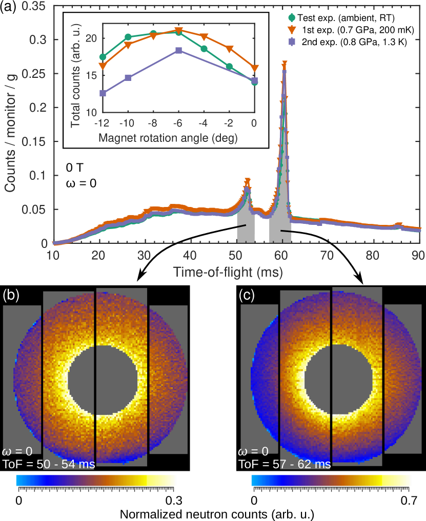
The total detector counts measured as a function of the neutron ToF are shown in Fig. 5(a) for three different pressure cells and samples. Regions of the detector containing nuclear Bragg peak intensity were excluded and hence the curves in Fig. 5(a) represent the background, which is due largely to the pressure cell. There are two prominent features at and on top of a very broad structure with maximum around . These features are also clearly present in Fig. 4(b). The intensity around the peaks has no structure in [Fig. 5(b)-(c)] and are believed to originate from multiple scattering involving the BeCu pressure cell and one of the upstream aluminum windows. The transmission is optimum around , which is why this particular magnet rotation angle was chosen for the inelastic neutron data collection. The small discrepancies between the curves in Fig. 5(a) (main panel and inset) are explained by slight differences in the cell orientation, which occur when mounting and aligning the cell by eye.
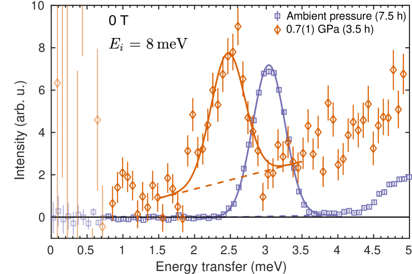
The pressure was determined by the energy shift of the first triplet excitation in SrCu2(BO3)2 at base temperature [Fig. 6]. The ambient-pressure reference was measured in a separate experiment without a pressure cell and a full treatment of these data is published elsewhere Fogh et al. (2024b). The integration ranges in Fig. 6 were , , for the curve at finite pressure and , , for the data at ambient pressure. The dispersionless nature of the triplet excitation in SrCu2(BO3)2 renders a direct comparison between the mode positions in such two regions of a valid approach. The large integration ranges were required to improve the neutron counting statistics. The resulting spectra were fitted to Gaussian profiles with a sloping background and the fitted center positions yielded a shift of . Using the linear relation, , between pressure and peak position given in Ref. Zayed et al., 2014 we obtain a pressure of . At this pressure, the transition field to the magnetization plateau is predicted to be Mila and Schmidt (2016); Haravifard et al. (2016), which means that it is sufficiently suppressed to be probed at the HFM/EXED facility.
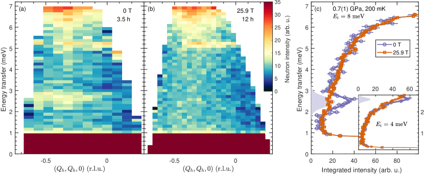
We now turn to finite magnetic fields where extensive diffraction data were collected at (34 h), (35 h) and (22 h). No magnetic-field-induced intensity was observed and we discuss the possible reasons for this further on. The inelastic signal at zero field and at is compared in Fig. 7(a)-(b). At zero field, the triplet excitation is located around and it is almost dispersionless as expected. At , the triplet excitation is no longer observed and the spectrum is almost featureless. As a general observation in both cases, the neutron intensity is larger for larger . Figure 7(c) shows the integrated neutron counts as a function of energy for the ranges , , for measurements with incoming energy and , and for measurements with incoming energy . The scattering intensity at is smeared out, which results in a slightly higher overall count rate but with no clear features compared to the zero-field spectrum. The resolution is improved when collecting data using , as shown in the inset of Fig. 7(c). Here, at zero field, the triplet mode is located at the edge of the accessible energy range and as a consequence its position is not well-determined. Nevertheless, it is clear that no new modes could be observed below the triplet at high fields.
We point out that the geometry of the HFM/EXED setup dictates that different values in correspond to different values in Fogh et al. (2024b); Allenspach et al. (2022). This is not a problem in the particular case of SrCu2(BO3)2 where the excitations are highly localized in all directions (and therefore show very little dispersion). In a system with more significant dispersion the approach of integrating over such a large volume of reciprocal space to improve the neutron statistics would be invalid.
We also note the spurious signal around in Fig. 7(a)-(b). This signal does not come from the pressure cell, as it was also seen in the ambient-pressure experiment Fogh et al. (2024b) but is most likely also not from the sample itself because the spurion position is independent of magnetic field and pressure. In the data measured with incoming energy , a corresponding spurion appears around . In the -integrated data shown in Fig. 7(c), a Gaussian with a linear background was fitted to the zero-field data to describe the spurious signal and subsequently subtracted.
V Discussion
Our work underlines the challenge of performing neutron scattering experiments under the simultaneous application of several extreme conditions. We discuss below the performance of the bullet cell, interpret the results and suggest improvements for future designs. We point out that the discontinued operation of the BER-II research reactor at the HZB impeded thorough testing of the bullet cell using well-known samples as well as empty-cell measurements. This limited available beamtime meant that we aimed directly for doing a real experiment which in turn carries a higher risk due to more unknown variables. Nevertheless, we succeeded in measuring an inelastic signal under conditions of , and .
Our pressure determination relies solely on the position of the triplet excitation of SrCu2(BO3)2 in zero field together with its known evolution with pressure Zayed et al. (2014). This is the main weakness of the setup and gives rise to a high uncertainty in the pressure determination. With the plateau extending for only a narrow field interval (around wide) at a given pressure Haravifard et al. (2016); Levy et al. (2008); Shi et al. (2022), it is easy to overshoot or undershoot with the field. Below the plateau resides a spin-nematic phase Fogh et al. (2024b), which is expected to be the ground state of the system at for pressures below Mila and Schmidt (2016). The spectrum in the spin-nematic phase was previously characterized both experimentally and theoretically Fogh et al. (2024b), and does not ressemble the results in Figs. 7(b)-(c). On the other hand, if the pressure is higher than estimated, then at the system could already be on the next plateau where the magnetization is of the saturated moment. Future pressure cell designs for similar setups should include an independent pressure gauge such as Pb or NaCl for more accurate pressure determination.
Whereas nuclear Bragg peaks from the sample were clearly visible, no magnetic-field-induced changes were observed in the neutron diffraction signal. This is expected in the spin-nematic phase at , where there is no long-range order. However, magnetic order is predicted at higher fields, i.e. both on the and plateaux Corboz and Mila (2014) but we observed no magnetic Bragg peaks or diffuse magnetic intensity. There are a number of reasons for why such signal may not appear: (1) Truly two-dimentional order leads to rods of scattering. In the experiment, we bisect only a finite volume of the rods and do not capture the full scattering intensity. Consequently the magnetic signal could be too weak to be observed in this experiment. (2) We rely on model predictions for the choice of range. If the model is wrong, we would simply be looking in the wrong part of reciprocal space. (3) The energy scale of the excitations on the plateau is likely lower compared to at zero field, which means that the temperature scale also decreases. Therefore, might not be cold enough to enter the plateau.
In general, when magnetic fields stronger than around are required, the only option currently available for neutron scattering experiments is that of pulsed magnetic fields. With this method, field strengths up to may be reached Duc et al. (2018); Fogh et al. (2020); Gazizulina et al. (2021); Holm-Janas et al. (2024), but only for a duration of a few milli seconds, which means a very low integrated measuring time. Consequently, this technique has to date only been suitable for diffraction studies where, as a rule, signals are orders of magnitudes stronger than inelastic signals. Combinations with pressures and dilution temperatures have not been attempted. The pulsed-field path is therefore limited in applications. Conversely, the results presented here demonstrate the feasibility of pressure-cell engineering for high-field magnets and may prove relevant for next-generation static magnets based on high- superconducting ceramic materials and delivering beyond Markiewicz et al. (2012); Bai et al. (2020). Moreover, our experiment was carried out on a medium-flux reactor but the future European Spallation Source will provide orders of magnitude higher neutron flux which render neutron scattering experiments using a similar combination of extreme conditions for studying quantum magnetic systems promising. Until such time, the bullet-type pressure cells have potential for use with existing static horizontal-field magnets at the various neutron facilities for combined pressure and field studies of spin textures with long periods such as skyrmions Mühlbauer et al. (2009), vortex lattices Xie et al. (2024) and spin spirals Romaguera and Medarde (2024).
VI Conclusions
We designed and constructed a pressure cell for neutron scattering experiments in combination with applied horizontal magnetic fields. Its bullet shape and optimized material choices enabled collection of inelastic neutron scattering and neutron diffraction data at , , and . Under these conditions it was possible to investigate the magnetization plateau in the frustrated quantum magnet SrCu2(BO3)2. Our work demonstrates the capabilities and future directions for combining the three extremes of high pressures, high magnetic fields and low temperatures for state-of-the-art neutron scattering experiments in the field of quantum magnetism.
Acknowledgements.
This work was funded by the European Research Council through the Synergy network HERO (Grant No. 810451) and by the Swiss National Science Foundation through Project Grant No. 188648. We would like to extend our gratitude to the team running the High Magnet Facility at the Helmholtz-Zentrum Berlin: many thanks to S. Gerischer, P. Heller, R. Wahle, S. Kempfer and P. Smeibidl for taking care of the dilution refrigerator and for making sure that the magnet was delivering its . E.F. is grateful to B. Normand for discussions and insight while shaping this work.Data Availability Statement
Raw data were generated at the BER-II research reactor at the Helmholtz-Zentrum Berlin. Derived data supporting the findings of this study are available from the corresponding author upon reasonable request.
Conflict of Interest Statement
The authors have no conflicts to disclose.
References
- Sachdev (2000) S. Sachdev, “Quantum Criticality: Competing Ground States in Low Dimensions,” Science 288, 475–480 (2000).
- Vasiliev et al. (2018) A. Vasiliev, O. Volkova, E. Zvereva, and M. Markina, “Milestones of low-D quantum magnetism,” npj Quant. Mater. 3, 18 (2018).
- Boothroyd (2020) A. T. Boothroyd, “Principles of Neutron Scattering from Condensed Matter,” (2020).
- (4) C. Goodway and O. Kirichek, Private communication.
- Neutron and Source (2022) ISIS Neutron and Muon Source, “Sample environment page,” (2022), access date: 2022-04-25.
- Laue-Langevin (2022) Institute Laue-Langevin, “Sample environment page,” (2022), access date: 2022-04-25.
- Khasanov et al. (2022) R. Khasanov, R. Urquhart, M. Elender, and Konstantin Kamenev, “Three-wall piston-cylinder type pressure cell for muon-spinrotation/relaxation experiments,” High Press. Res. 42, 29–46 (2022).
- Institute (2022) Paul Scherrer Institute, “Sample environment page,” (2022), access date: 2022-04-25.
- Aso et al. (2007) N. Aso, T. Fujiwara, Y. Uwatoko, H. Miyano, and H. Yoshizawa, “Development of a hybrid CuBe/NiCrAl clamp-type high pressure cell for neutron diffraction,” J. Phys. Soc. Jpn. 76, 228–229 (2007).
- Kaneko et al. (2024) K. Kaneko, C. Tabata, M. Hagihala, H. Yamauchi, Y. Oba, T. Kumada, M. Kubota1, Y. Kojima1, N. Nabatame, M. Sasaki1, Y. Shimojo, K. Kodama, and T. Osakabe, “New Standard for Low Temperature Sample Environment at JAEA/JRR-3,” JPS Conf. Proc. 41, 011015 (2024).
- Osakabe et al. (2010) T. Osakabe, K. Kuwahara, D. Kawana, K. Iwasa, D. Kikuchi, Y. Aoki, M. Kohgi, and H. Sato, “Pressure-Induced Antiferromagnetic Order in Filled Skutterudite PrFe4P12 Studied by Single-Crystal High-Pressure Neutron Diffraction,” J. Phys. Soc. Jpn. 79, 034711 (2010).
- Dissanayake et al. (2019) S. E. Dissanayake, M. Matsuda, K. Munakata, H. Kagi, J. Gouchi, and Y. Uwatoko, “Development of cubic anvil type high pressure apparatus for neutron diffraction,” J. Phys.: Condens. Matter 31, 384001 (2019).
- Komatsua et al. (2015) K. Komatsua, K. Munakata, K. Matsubayashi, Y. Uwatokoc, Y. Yokoyamad, K. Sugiyamad, and M. Matsuda, “Zr-based bulk metallic glass as a cylinder material for high pressure apparatuses,” High. Press. Res. 35, 54–262 (2015).
- Prokhnenko et al. (2015) O. Prokhnenko, W.-D. Stein, H.-J. Bleif, M. Fromme, M. Bartkowiak, and T. Wilpert, “Time-of-flight extreme environment diffractometer at the Helmholtz-Zentrum Berlin,” Rev. Sci. Instrum. 86, 033102 (2015).
- Smeibidl et al. (2016) P. Smeibidl, M. Bird, H. Ehmler, I. Dixon, J. Heinrich, M. Hoffmann, S. Kempfer, S. Bole, J. Toth, O. Prokhnenko, and B. Lake, “First hybrid magnet for neutron scattering at Helmholtz-Zentrum Berlin,” IEEE Trans. Appl. Supercond. 26, 4301606 (2016).
- Prokhnenko et al. (2016) O. Prokhnenko, M. Bartkowiak, W.-D. Stein, N. Stuesser, H.-J. Bleif, M. Fromme, K. Prokes, P. Smeibidl, M. Bird, and B. Lake, “HFM-EXED - the high field facility for neutron scattering at HZB,” Proceedings of ICANS-XXI , 278–285 (2016).
- Prokhnenko et al. (2017) O. Prokhnenko, P. Smeibidl, W. D. Stein, M. Bartkowiak, and N. Stuesser, “HFM/EXED: The High Magnetic Field Facility for Neutron Scattering at BER II,” JLSRF 3, A115 (2017).
- Kozlenko et al. (2008) D. P. Kozlenko, I. Mirebeau, J.-G. Park, I. N. Goncharenko, S. Lee, J. Park, and B. N. Savenko, “High-pressure-induced spin-liquid phase of multiferroic YMnO3,” Phys. Rev. B 78, 054401 (2008).
- Rüegg et al. (2008) Ch. Rüegg, B. Normand, M. Matsumoto, A. Furrer, D. F. McMorrow, K. W. Krämer, H.-U. Güdel, S. N. Gvasaliya, H. Mutka, and M. Boehm, “Quantum Magnets under Pressure: Controlling Elementary Excitations in TlCuCl3,” Phys. Rev. Lett. 100, 205701 (2008).
- Terada et al. (2020) N. Terada, C. V. Colin, N. Qureshi, T. C. Hansen, K. Matsubayashi, Y. Uwatoko, and A. A. Belik, “Pressure-induced incommensurate antiferromagnetic order in a ferromagnetic B-site ordered double-perovskite Lu2NiMnO6,” Phys. Rev. B 102, 094412 (2020).
- Fogh et al. (2024a) E. Fogh, G. Giriat, M. E. Zayed, A. Piovano, M. Boehm, P. Steffens, I. Safiulina, U. B. Hansen, S. Klotz, J.-R. Soh, E. Pomjakushina, F. Mila, B. Normand, and H. M. Rønnow, “Spin waves and three-dimensionality in the high-pressure antiferromagnetic phase of SrCu2(BO3)2,” (2024a), arXiv:2406.17546 [cond-mat] .
- Klotz et al. (2016) S. Klotz, Th. Strässle, B. Lebert, M. d’Astuto, and Th. Hansen, “High pressure neutron diffraction to beyond 20 GPa and below 1.8 K using Paris-Edinburgh load frames,” High Press. Res. 36, 73–78 (2016).
- Sears (1992) V. F. Sears, “Neutron scattering lengths and cross sections,” Neutron News 3, 26–27 (1992).
- Miyahara and Ueda (1999) S. Miyahara and K. Ueda, “Exact dimer ground state of the two-dimensional Heisenberg spin system SrCu2(BO3)2,” Phys. Rev. Lett. 82, 3701 (1999).
- Shastry and Sutherland (1981) B. S. Shastry and B. Sutherland, “Exact ground state of a quantum mechanical antiferromagnet,” Physica B+C 108, 1069 (1981).
- Kageyama et al. (1999a) H. Kageyama, K. Yoshimura, R. Stern, N. V. Mushnikov, K. Onizuka, M. Kato, K. Kosuge, C. P. Slichter, T. Goto, and Y. Ueda, “Exact dimer ground state and quantized magnetization plateaus in the two-dimensional spin system SrCu2(BO3)2,” Phys. Rev. Lett. 82, 3168 (1999a).
- Kageyama et al. (2000a) H. Kageyama, M. Nishi, N. Aso, K. Onizuka, T. Yosihama, K. Nukui, K. Kodama, K. Kakurai, and Y. Ueda, “Direct evidence for the localized single-triplet excitations and the dispersive multitriplet excitations in SrCu2(BO3)2,” Phys. Rev. Lett. 84, 5876 (2000a).
- Kageyama et al. (2000b) H. Kageyama, K. Onizuka, Y. Ueda, M. Nohara, H. Suzuki, and H. Takagi, “Low-temperature specific heat study of SrCu2(BO3)2 with an exactly solvable ground state,” J. Exp. Theor. Phys. 90, 129 (2000b).
- Gaulin et al. (2004) B. D. Gaulin, S. H. Lee, S. Haravifard, J. P. Castellan, A. J. Berlinsky, H. A. Dabkowska, Y. Qiu, and J. R. D. Copley, “High-resolution study of spin excitations in the singlet ground state of SrCu2(BO3)2,” Phys. Rev. Lett. 93, 267202 (2004).
- Kakurai et al. (2005) K. Kakurai, K. Nukui, N. Aso, M. Nishi, H. Kadowaki, H. Kageyama, Y. Ueda, L-P. Regnault, and O. Cépas, “Neutron Scattering Investigation on Quantum Spin System SrCu2(BO3)2,” Progress of Theoretical Physics Supplement 159, 22 (2005).
- Koga and Kawakami (2000) A. Koga and N. Kawakami, “Quantum Phase Transitions in the Shastry-Sutherland Model for SrCu2(BO3)2,” Phys. Rev. Lett. 84, 4461–4464 (2000).
- Chung et al. (2001) C. H. Chung, J. B. Marston, and S. Sachdev, “Quantum phases of the Shastry-Sutherland antiferromagnet: Application to SrCu2(BO3)2,” Phys. Rev. B 64, 134407 (2001).
- Läuchli et al. (2002) A. Läuchli, S. Wessel, and M. Sigrist, “Phase diagram of the quadrumerized Shastry-Sutherland model,” Phys. Rev. B 66, 014401 (2002).
- Corboz and Mila (2013) P. Corboz and F. Mila, “Tensor network study of the Shastry-Sutherland model in zero magnetic field,” Phys. Rev. B 87, 115144 (2013).
- Nakano and Sakai (2018) H. Nakano and T. Sakai, “Third Boundary of the Shastry–Sutherland Model by Numerical Diagonalization,” J. Phys. Soc. Jpn. 87, 123702 (2018).
- Xi et al. (2023) N. Xi, H. Chen, Z. Y. Xie, and R. Yu, “Plaquette valence bond solid to antiferromagnet transition and deconfined quantum critical point of the Shastry-Sutherland model,” Phys. Rev. B 107, L220408 (2023).
- Onizuka et al. (2000) K. Onizuka, H. Kageyama, Y. Narumi, K. Kindo, Y. Ueda, and T. Goto, “1/3 magnetization plateau in SrCu2(BO3)2 - stripe order of excited triplets -,” J. Phys. Soc. Jpn. 69, 1016 (2000).
- Takigawa et al. (2013) M. Takigawa, M. Horvatić, T. Waki, S. Krämer, C. Berthier, F. Lévy-Bertrand, I. Sheikin, H. Kageyama, Y. Ueda, and F. Mila, “Incomplete Devil’s Staircase in the Magnetization Curve of SrCu2(BO3)2,” Phys. Rev. Lett. 110, 067210 (2013).
- Matsuda et al. (2013) Y. H. Matsuda, N. Abe, S. Takeyama, H. Kageyama, P. Corboz, A. Honecker, S. R. Manmana, G. R. Foltin, K. P. Schmidt, and F. Mila, “Magnetization of SrCu2(BO3)2 in Ultrahigh Magnetic Fields up to 118 T,” Phys. Rev. Lett. 111, 137204 (2013).
- Shi et al. (2022) Z. Shi, S. Dissanayake, P. Corboz, W. Steinhardt, D. Graf, D. M. Silevitch, H. A. Dabkowska, T. F. Rosenbaum, F. Mila, and S. Haravifard, “Discovery of quantum phases in the Shastry-Sutherland compound SrCu2(BO3)2 under extreme conditions of field and pressure,” Nat. Commun. 13, 2301 (2022).
- Nomura et al. (2023) T. Nomura, P. Corboz, A. Miyata, S. Zherlitsyn, Y. Ishii, Y. Kohama, Y. H. Matsuda, A. Ikeda, C. Zhong, H. Kageyama, and F. Mila, “Unveiling new quantum phases in the Shastry-Sutherland compound SrCu2(BO3)2 up to the saturation magnetic field,” Nat. Commun. 14, 3769 (2023).
- Corboz and Mila (2014) P. Corboz and F. Mila, “Crystals of bound states in the magnetization plateaus of the Shastry-Sutherland model,” Phys. Rev. Lett. 112, 147203 (2014).
- Haravifard et al. (2016) S. Haravifard, D. Graf, A. E. Feiguin, C. D. Batista, J. C. Lang, D. M. Silevitch, G. Srajer, B. D. Gaulin, H. A. Dabkowska, and T. F. Rosenbaum, “Crystallization of spin superlattices with pressure and field in the layered magnet SrCu2(BO3)2,” Nat. Commun. 7, 11956 (2016).
- Mila and Schmidt (2016) D. A. Schneider K. Coester F. Mila and K. P. Schmidt, “Pressure dependence of the magnetization plateaus of SrCu2(BO3)2,” Phys. Rev. B 93, 241107(R) (2016).
- Kageyama et al. (1999b) H. Kageyama, K. Onizuka, T. Yamauchi, and Y. Ueda, “Crystal growth of the two-dimensional spin gap system SrCu2(BO3)2,” J. Cryst. Growth 206, 65–67 (1999b).
- Jorge et al. (2004) G. Jorge, M. Jaime, N. Harrison, R. Stern, H. Dabkowska, and B. D. Gaulin, “High magnetic field magnetization and specific heat of the 2D spin–dimer system SrCu2(BO3)2,” J. Alloys Compd. 369, 90–92 (2004).
- Bartkowiak et al. (2020) M. Bartkowiak, K. Prokeš, M. Fromme, A. Budack, J. Dirlick, and O. Prokhnenko, “Exeq and inexeq: software tools for experiment planning at the extreme environment diffractometer,” J. Appl. Cryst. 53, 1613–1619 (2020).
- Fogh et al. (2024b) E. Fogh, M. Nayak, O. Prokhnenko, M. Bartkowiak, K. Munakata, J.-R. Soh, A. A. Turrini, M. E. Zayed, E. Pomjakushina, H. Kageyama, H. Nojiri, K. Kakurai, B. Normand, F. Mila, and H. M. Rønnow, “Field-induced bound-state condensation and spin-nematic phase in SrCu2(BO3)2 revealed by neutron scattering up to 25.9 T,” Nat. Commun. 15, 442 (2024b).
- Zayed et al. (2014) M. E. Zayed, Ch. Rüegg, Th. Strässle, U. Stuhr, B. Roessli, M. Ay, J. Mesot, P. Link, E. Pomjakushina, M. Stingaciu, K. Conder, and H. M. Rønnow, “Correlated decay of triplet excitations in the Shastry-Sutherland compound SrCu2(BO3)2,” Phys. Rev. Lett. 113, 067201 (2014).
- Allenspach et al. (2022) S. Allenspach, A. Madsen, A. Biffin, M. Bartkowiak, O. Prokhnenko, A. Gazizulina, X. Liu, R. Wahle, S. Gerischer, S. Kempfer, P. Heller, P. Smeibidl, A. Mira, N. Laflorencie, F. Mila, B. Normand, and Ch. Rüegg, “Investigating field-induced magnetic order in Han purple by neutron scattering up to 25.9 T,” Phys. Rev. B 106, 104418 (2022).
- Levy et al. (2008) F. Levy, I. Sheikin, C. Berthier, M. Horvatić, M. Takigawa, H. Kageyama, T. Waki, and Y. Ueda, EPL 81, 67004 (2008).
- Duc et al. (2018) F. Duc, X. Tonon, J. Billette, B. Rollet, W. Knafo, F. Bourdarot, J. Béard, F. Mantegazza, B. Longuet, J. E. Lorenzo, E. Lelièvre-Berna, P. Frings, and L.-P. Regnault, “40-Tesla pulsed-field cryomagnet for single crystal neutron diffraction,” Rev. Sci. Instrum. 89, 053905 (2018).
- Fogh et al. (2020) E. Fogh, T. Kihara, R. Toft-Petersen, M. Bartkowiak, Y. Narumi, O. Prokhnenko, A. Miyake, M. Tokunaga, K. Oikawa, M. K. Sørensen, J. C. Dyrnum, H. Grimmer, H. Nojiri, and N. B. Christensen, “Magnetic structures and quadratic magnetoelectric effect in LiNiPO4 beyond 30 T,” Phys. Rev. B 101, 024403 (2020).
- Gazizulina et al. (2021) A. Gazizulina, D. L. Quintero-Castro, Z. Wang, F. Duc, F. Bourdarot, K. Prokes, W. Schmidt, R. Daou, S. Zherlitsyn, N. Islam, N. H. Kolnes, A. B. Kademane, A. Schilling, and B. Lake, “Neutron diffraction of field-induced magnon condensation in the spin-dimerized antiferromagnet Sr3Cr2O8,” Phys. Rev. B 104, 064430 (2021).
- Holm-Janas et al. (2024) S. Holm-Janas, M. Akaki, E. Fogh, T. Kihara, M. D. Le, P. C. Forino, S. E. Nikitin, T. Fennell, A. Painganoor, D. Vaknin, M. Watanabe, N. B. Christensen, H. Nojiri, and R. Toft-Petersen, “Magnetic structure and magnetoelectric properties of the spin-flop phase in LiFePO4,” Phys. Rev. B 109, 174413 (2024).
- Markiewicz et al. (2012) W. D. Markiewicz, D. C. Larbalestier, H W. Weijers, A. J. Voran, K. W. Pickarda, W. R. Sheppard, J. Jaroszynski, A. Xu, R. P. Walsh, J. Lu, A. V. Gavrilin, and P. D. Noyes, “Design of a Superconducting 32 T Magnet With REBCO High Field Coils,” IEEE Trans. Appl. Supercond. 22, 4300704 (2012).
- Bai et al. (2020) H. Bai, M. D. Bird, L. D. Cooley, I. R. Dixon, K. L. Kim, D. C. Larbalestier, W. S. Marshall, U. P. Trociewitz, H. W. Weijers, D. V. Abraimov, and G. S. Boebinger, “The 40 T Superconducting Magnet Project at the National High Magnetic Field Laboratory,” IEEE Trans. Appl. Supercond. 30, 4300405 (2020).
- Mühlbauer et al. (2009) S. Mühlbauer, B. Binz, F. Jonietz, C. Pfleiderer, A. Rosch, A. Neubauer, R. Georgii, and P. Böni, “Skyrmion Lattice in a Chiral Magnet,” Science 323, 915–919 (2009).
- Xie et al. (2024) Y. Xie, N. Chalus, Z. Wang, W. Yao, J. Liu, Y. Yao, J. S. White, L. M. DeBeer-Schmitt, J.-X. Yin, P. Dai, and M. R. Eskildsen, “Conventional superconductivity in the doped kagome superconductor Cs(V0.86Ta0.14)3Sb5 from vortex lattice studies,” Nat. Commun. 15, 6467 (2024).
- Romaguera and Medarde (2024) A. Romaguera and M. Medarde, “Room temperature magnetoelectric magnetic spirals by design,” Front. Mater. 11, 144876 (2024).