Intertwined Fano resonances in sub-wavelength metallic gratings: omnidirectional and wideband optical transmission
Abstract
Metallic gratings can be used as infrared filters, but their performance is often limited by bandwidth restrictions due to metallic losses. In this work, we propose a metallic groove-slit-groove (GSG) structure that overcomes these limitations by exhibiting a large bandwidth, angularly independent, extraordinary optical transmission. Our design achieves high transmission efficiency in the longwave infrared range, driven by Fano-type resonances created through the interaction between the grooves and the central slit. This mechanism results in a tunable transmission window with high rejection rate. We extend the concept to a two-dimensional GSG array, exhibiting a polarization insensitive 80% transmission window for incident angles up to 50°, offering significant potential for infrared filtering applications.
Metallic films patterned with holes or slit arrays can exhibit the so-called extraordinary optical transmission phenomenon [1, 2, 3]. It was given its name since the transmission efficiency outperforms both the geometrical aperture ratio, as well as the transmission expected from diffraction theory by a single hole [4]. This extraordinary transmission can be explained by the presence of plasmonic resonances, either propagative (for a periodic array of slits) or localized in a cavity (for a Fabry-Perot type slit) [5, 6]. These seminal demonstrations have been applied to spectral filters from the visible range [7] to the THz [8] and are particularly appealing for infrared multispectral imaging compared to thin film technology [9, 10, 11, 12, 13, 14].
Yet, these solutions suffer from various drawbacks. First, the transmission follows in most cases a lorentzian shape with a full width at half maximum (FWHM) that cannot be easily modified. Besides, nanostructured filters that rely on propagative resonances are very sensitive to the incidence angle thus restricting them to applications with limited numerical apertures [15]. In contrast, Fabry-Perot resonances are able to sustain angularly stable resonances, and can be obtained with a slit array in a metallic film of a typical quarter wavelength thickness [16], but their FWHM remains determined by the material losses, thus limiting their bandwidth.
Here, we theoretically investigate a metallic groove-slit-groove (GSG) structure that supports localized resonances and exhibits bandpass-like filtering in the mid-infrared. We begin by showing the complete structure under study in this article, and comparing it to the well-known slit-array. The rest of the article is devoted to explaining the optical behavior at play. To this end, we show that one groove associated with a slit (SG structure), each supporting a Fabry-Perot like resonance, leads to a Fano-type profile with a larger bandwidth. We then show that the combination of a slit with two grooves behaves as an angularly stable transmission filter of tunable bandwidth. We extend these results to unpolarized filters and demonstrate an omnidirectional high transmission filter.
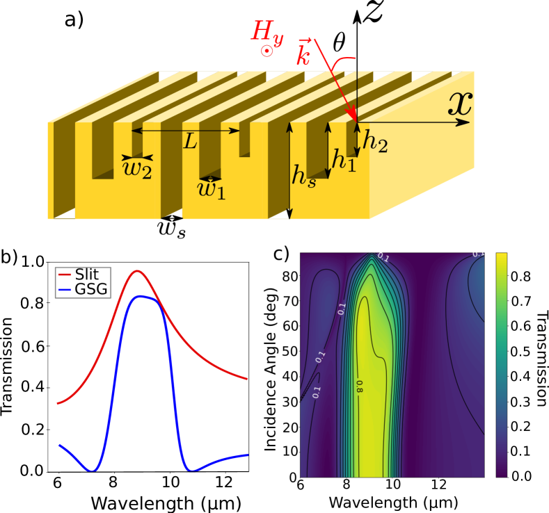
The scheme of the GSG structure is presented on Fig. 1a). Its unit-cell consists of one slit and two grooves repeated with a period , and light is impinging on the structure with an angle and a transverse magnetic (TM) polarization. The metal here is gold, though it has little incidence on the overall behavior, as the wavelength is far beyond the plasma frequency.
The transmission spectrum of this GSG structure at normal incidence is shown in Fig. 1b), demonstrating its band-pass behavior centered at 9. The key features of this structure are first its 80% transmission plateau with a spectral width of 1. Second, on each side of the resonance, there is a zero of transmission and then a low value of transmission (below 10%) that yields good rejection performance for a plasmonic filter. To highlight the performance of our structure, the transmission spectrum of a simple slit array of same dimensions is also shown in Fig. 1b). It behaves as a Fabry-Perot cavity in transmission, whose resonance wavelength is set by the optical length of the slit as (here due to the coupling of the surface plasmons on the cavity sidewalls and accounts for the reflection phase shift at both slit interfaces) [2]. The slits of the GSG structures also behave as Fabry-Perot cavities with a back mirror reflection, thus their resonance wavelength is given by [17].
The transmission spectrum for varying angular incidence is shown in Fig. 1c), demonstrating that these filtering properties have a high angular tolerance, with the 80% high, 2 wide transmission bandwidth being exhibited on a range. Between and , the transmission remains higher than 70% on the plateau bandwidth (8.5 to 9.5 ). The resonances spectral positions are angularly stable up to grazing incidence but the transmission amplitude and the bandwidth are gradually decreasing. Remarkably, the zero of transmission at is stable up to grazing incidence, while the one at is perturbed by the diffraction order for angles higher than .
The angular tolerance of this structure is expected, given the nature of the resonances at play. Indeed, the Fabry-Perot cavities made by the metallic slits are known to exhibit particularly angularly stable resonances [16]. As these resonances control the optical transmission of the structure, the final transmission spectrum is also angularly stable. This also implies that the spectrum shape (zeros and maximum) are easily controlled by tuning the dimensions of the slits and grooves, as will be detailed further below.
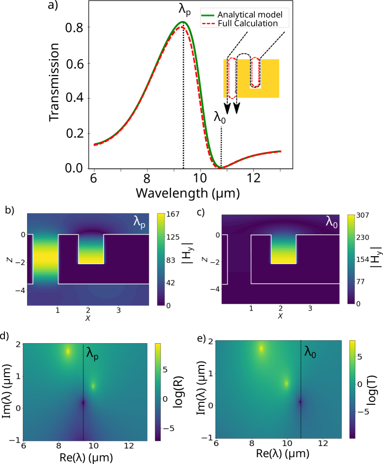
The particular shape of the extraordinary optical transmission resonance is due to the participation of two different Fano interferences [18, 19]. Each of these Fano interferences arises from the combination of the resonances of the slit and of one of the grooves. To confirm this, the transmission of the slit and the first groove (SG1 structure) with the same dimensions and the same period is plotted in Fig. 2a). It exhibits the typical lineshape of a Fano interference. The inset shows schematically the explanation of this phenomenon, i.e. two optical paths that interfere in the structure, giving rise to interferences. The spectra in Fig. 2a) are computed independently by an analytical one-mode model [20] and a full field modal method [21]. The perfect agreement between both simulations shows that only the fundamental mode has to be taken into account to explain the spectral profile, which is consistent with the Fano interference explanation.
The magnetic field amplitude maps in Fig. 2b-c) show that at the resonance peak (), both the slit and the groove are concentrating the field and thus playing a role on the resonance. This hints at a coupling mechanism which slightly modifies the resonance frequencies. A detailed study of the resonant modes can be found in the Supplementary Material. On the other hand, at the resonance dip (), the field is concentrated only in the groove, prohibiting the transmission. To investigate further the mechanism at stake, we use the singular analysis approach in the domain of complex frequencies. In this case, the scattering matrix can be written as , where and are poles and zeros, and a scaling constant [22]. The combination of a pole and a zero with different real part of the frequency makes a Fano profile appear, leading to the sharp slope between the maximum transmission and zero transmission [23]. The complex pole study in Fig. 2d-e) shows the resonant behavior of the SG combination. The slit alone has a resonance corresponding to the pole at . However, when combined with the slit, a pole-zero combination appears for the transmission around 10.5, as seen on Fig. 2d), leading to a sharp Fano profile. The transmission maximum itself is better seen with the zero of the reflection on Fig. 2e).
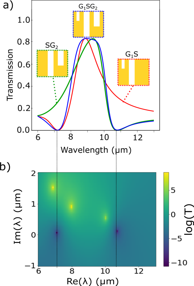
This analysis can be applied to the complete GSG structure to demonstrate that it behaves as the combination of two independent Fano profiles. The transmission spectrum of the GSG structure is compared to both SG structures in Fig. 3. The resonant transmission of the complete structure is surrounded by two transmission zeros at and . Each of these zeros corresponds to a Fano profile exhibited by a given SG combination that follows the classical form , where is the Fano parameter that depends on the phase difference between the resonator and the continuum (see Supp. Mat. for values of q in SG structures) and that dictates the asymmetry of the response and is the normalized frequency detuning with the resonator. Indeed, the green (resp. red) curve on Fig. 3 corresponds to the transmission spectrum of the slit and the deeper groove (resp. shallower groove), exhibiting a Fano profile with zero at (resp. ). Remarkably, when the GSG combination is done, the zeros are identical to the individual SG ones (see supplemental material). The response of the GSG structure can be described as the product of the two individual Fano responses , and in that optimized structure, .
The complex pole study of this full structure in Fig. 3 confirms this interpretation: each zero in the transmission is close to, but not vertically aligned with, a transmission pole. The transmission band is thus widened by the combination of the two transmission peaks, and the slopes between the peak and the zeros are sharpened due to the Fano profile.
This Fano behavior can easily be tuned by choosing different depths for the slits and grooves. Though a coupling between the slit and groove modes appears, leading to non-trivial shifts in the resonances (see Supp. Mat.), a reliable rule of thumb for the structure design is the following. First, the central wavelength of the transmission band is controlled by the resonance wavelength of the slit that acts as a half-wavelength resonator. The bandwidth is controlled by the quarter-wavelength resonance of the two grooves, and that defined the transmission zeros on each side of the transmission band. These values must take into account the phase offset induce by the reflections inside each cavity as wemm as the effective index [24]. Besides, if the structure is buried or filled with a given material, all the depths must be divided by the refractive index. Though similar ”free standing” structures have already been fabricated [3], the use of a low refractive index substrate would slightly affect the transmission (see supp. Mat.).
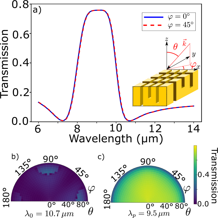
In order to extend the angular stability of this filter to azimuthal variations, it is possible to use a 3D structured surface, where slits and grooves are etched in perpendicular directions. The unit cell of this structure is shown in inset of Figure 4. On Figure 4a) are shown transmission spectra for various incident polarization of azimuthal angle and computed with RCWA [25]. These spectra show that the 3D structure has exactly the same response in transmission as the 2D structure.
Figure 4b-c) shows polar representations of the evolution of the transmission at the resonance zero (Figure 4b) and peak (Figure 4c)) as a function of both polar and azimuthal angles. We can see that the resonance is very stable and polarization-insensitive, to the same degree as the 2D structure.
In conclusion, we have demonstrated numerically the characteristics of a band-pass filter of tunable bandwidth and wavelength, whose main asset is its large angular stability (-50°,+50°). The double Fano profile mechanism giving rise to this behavior was explained and verified, giving valuable insights to design similar structures.
Funding
This work was supported by an AID scholarship
Disclosures
The authors declare no conflicts of interest.
Data availability
Data underlying the results presented in this paper can be obtained from the authors upon reasonable request.
Supplemental document
See Supplement 1 for supporting content.
References
- Ebbesen et al. [1998] T. W. Ebbesen, H. J. Lezec, H. Ghaemi, T. Thio, and P. A. Wolff, Extraordinary optical transmission through sub-wavelength hole arrays, nature 391, 667 (1998).
- Porto et al. [1999] J. Porto, F. Garcia-Vidal, and J. Pendry, Transmission resonances on metallic gratings with very narrow slits, Physical review letters 83, 2845 (1999).
- Collin et al. [2010] S. Collin, G. Vincent, R. Haïdar, N. Bardou, S. Rommeluère, and J.-L. Pelouard, Nearly perfect fano transmission resonances through nanoslits drilled in a metallic membrane, Physical review letters 104, 027401 (2010).
- Bethe [1944] H. A. Bethe, Theory of diffraction by small holes, Physical review 66, 163 (1944).
- Garcia-Vidal et al. [2010] F. J. Garcia-Vidal, L. Martin-Moreno, T. Ebbesen, and L. Kuipers, Light passing through subwavelength apertures, Reviews of Modern Physics 82, 729 (2010).
- Collin [2014] S. Collin, Nanostructure arrays in free-space: optical properties and applications, Reports on Progress in Physics 77, 126402 (2014).
- Miyamichi et al. [2018] A. Miyamichi, A. Ono, H. Kamehama, K. Kagawa, K. Yasutomi, and S. Kawahito, Multi-band plasmonic color filters for visible-to-near-infrared image sensors, Optics express 26, 25178 (2018).
- Wu et al. [2003] D. Wu, N. Fang, C. Sun, X. Zhang, W. J. Padilla, D. N. Basov, D. R. Smith, and S. Schultz, Terahertz plasmonic high pass filter, Applied Physics Letters 83, 201 (2003).
- Haïdar et al. [2010] R. Haïdar, G. Vincent, S. Collin, N. Bardou, N. Guérineau, J. Deschamps, and J.-L. Pelouard, Free-standing subwavelength metallic gratings for snapshot multispectral imaging, Applied Physics Letters 96 (2010).
- Duempelmann et al. [2017] L. Duempelmann, B. Gallinet, and L. Novotny, Multispectral imaging with tunable plasmonic filters, ACS Photonics 4, 236 (2017).
- Pelzman and Cho [2018] C. Pelzman and S.-Y. Cho, Multispectral and polarimetric photodetection using a plasmonic metasurface, Journal of Applied Physics 123 (2018).
- Stewart et al. [2020] J. W. Stewart, J. H. Vella, W. Li, S. Fan, and M. H. Mikkelsen, Ultrafast pyroelectric photodetection with on-chip spectral filters, Nature materials 19, 158 (2020).
- Shaik et al. [2023] N. E. K. Shaik, B. Widdicombe, D. Sun, S. E. John, D. Ryu, A. Nirmalathas, and R. R. Unnithan, Longwave infrared multispectral image sensor system using aluminum-germanium plasmonic filter arrays, Nano Research 16, 10018 (2023).
- Ding et al. [2024] K. Ding, M. Wang, M. Chen, X. Wang, K. Ni, Q. Zhou, and B. Bai, Snapshot spectral imaging: from spatial-spectral mapping to metasurface-based imaging, Nanophotonics 13, 1303 (2024).
- Davis et al. [2017] M. S. Davis, W. Zhu, T. Xu, J. K. Lee, H. J. Lezec, and A. Agrawal, Aperiodic nanoplasmonic devices for directional colour filtering and sensing, Nature communications 8, 1347 (2017).
- Astilean et al. [2000] S. Astilean, P. Lalanne, and M. Palamaru, Light transmission through metallic channels much smaller than the wavelength, Optics Communications 175, 265 (2000).
- Bouchon et al. [2011] P. Bouchon, F. Pardo, B. Portier, L. Ferlazzo, P. Ghenuche, G. Dagher, C. Dupuis, N. Bardou, R. Haïdar, and J.-L. Pelouard, Total funneling of light in high aspect ratio plasmonic nanoresonators, Applied Physics Letters 98 (2011).
- Limonov et al. [2017] M. F. Limonov, M. V. Rybin, A. N. Poddubny, and Y. S. Kivshar, Fano resonances in photonics, Nature photonics 11, 543 (2017).
- Limonov [2021] M. F. Limonov, Fano resonance for applications, Advances in optics and photonics 13, 703 (2021).
- Langevin et al. [2020] D. Langevin, E. El Shamy, J. Jaeck, R. Haïdar, and P. Bouchon, Study of disordered metallic groove arrays with a one-mode analytical model, Optics Express 28, 22549 (2020).
- Bouchon et al. [2010] P. Bouchon, F. Pardo, R. Haïdar, and J.-L. Pelouard, Fast modal method for subwavelength gratings based on b-spline formulation, JOSA A 27, 696 (2010).
- Grigoriev et al. [2013a] V. Grigoriev, A. Tahri, S. Varault, B. Rolly, B. Stout, J. Wenger, and N. Bonod, Optimization of resonant effects in nanostructures via weierstrass factorization, Physical Review A 88, 011803 (2013a).
- Grigoriev et al. [2013b] V. Grigoriev, S. Varault, G. Boudarham, B. Stout, J. Wenger, and N. Bonod, Singular analysis of fano resonances in plasmonic nanostructures, Physical Review A 88, 063805 (2013b).
- Collin et al. [2007] S. Collin, F. Pardo, and J.-L. Pelouard, Waveguiding in nanoscale metallic apertures, Optics Express 15, 4310 (2007).
- Langevin et al. [2024] D. Langevin, P. Bennet, and A. Moreau, Rcwa, RCWA code available at https://github.com/Milloupe/Code_RCWA (2024).