Spectroscopy of the spin waves of a synthetic antiferromagnet grown on a piezoelectric substrate
Abstract
Efficient coupling between magnons and phonons requires material platforms that contain magnetic multilayers with versatile high-frequency properties grown on piezoelectric substrates with large electromechanical coupling coefficients. One of these systems is the CoFeB/Ru/CoFeB Synthetic antiferromagnet grown on Lithium Niobate substrate. We investigate its microwave magnetic properties using a combination of ferromagnetic resonance and propagating spin wave spectroscopy, from which we extract the dispersion relation of the acoustic branch of spin waves. The frequency and the linewidth of this spin wave resonance, its field dependence and its dispersion relation indicate that the magnetic properties are as good as when grown on standard non-piezoelectric substrates, as well as being in line with theory. This new material platform opens opportunities to extend microwave acousto-magnonics beyond the use of single layer magnets.
I Introduction
Devices exploiting surface acoustic waves (SAWs) play a significant role in numerous modern technological applications, ranging from wireless communications [1] to medicine [2], sensors [3], and RF signal processing in telecommunications. However, they have certain limitations, such as a reciprocal propagation and the near-absence of tunability. Circumventing these limitations may be possible by coupling SAWs with magnons [4, 5, 6, 7, 8, 9, 10, 11] since the latter feature tunability and non-reciprocity. In particular, the spin waves (SWs) within magnetic bilayers have attracted interest [12] because of their convenient high frequency SWs with long propagation lengths. Ensuring the high quality of both the magnetic thin film and the piezoelectric substrate is crucial to benefit from the SAW-SW coupling.
In this study, we investigate SWs within a synthetic antiferromagnet (SAF) grown on a piezoelectric lithium niobate substrate LiNbO3. The SAF consists of two magnetic layers of CoFeB, separated by a non-magnetic spacer layer mediating antiferromagnetic coupling. The SAF exhibits two eigenmodes: the optical mode and the acoustic mode, characterized by out-of-phase and in-phase precession of the magnetizations, respectively [13, 14, 15, 16, 17, 18]. It is known that the SW properties are very sensitive to the material structure, the roughness and the interdiffusion inside the stack [19]. Here we measure the properties of acoustic SWs using inductive techniques and demonstrate that it is possible to grow high-quality SAFs on high performing LiNbO3 piezoelectric substrates.
II Materials and devices
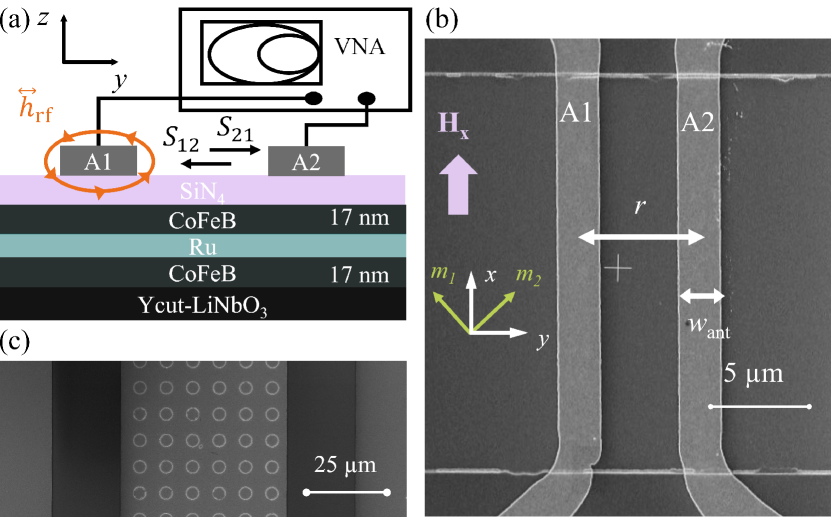
We use a SAF of composition LiNbO3 (Y-cut substrate)/Ta /Co40Fe40B20( nm) /Ru(0.7nm) /Co40Fe40B20() /Ru /Ta(cap) [Fig. 1.(a)]. The CoFeB has a magnetization and an interlayer exchange field mT. We pattern [18] the SAF into stripes of width m and much longer length. We cover the sample with and fabricate two micrometer-sized single wire antennas of widths and variable center-to-center distances from 3.4 to 6 m [Fig. 1(c)]. This device will be used to perform propagating spin waves spectroscopy (PSWS) and compare the material quality to existing benchmarks. The analysis of PSWS data will require the knowledge of the resonant frequencies of uniform SWs, for which we fabricate an additional device to perform VNA-FMR [20]. To ensure comparability, the VNA-FMR device is built on the same chip as the PSWS device. It consists of an array of circular 4 m dots 111The geometry were chosen to reduce the effect of shape anisotropy. inductively coupled to a much wider coplanar waveguide [Fig. 1(b)], which excites the uniform SW modes. The linewidth and the resonant frequencies of the uniform acoustic and optical spin wave modes shall provide the value of and of the damping parameter .
III Ferromagnetic resonance of the acoustic spin waves
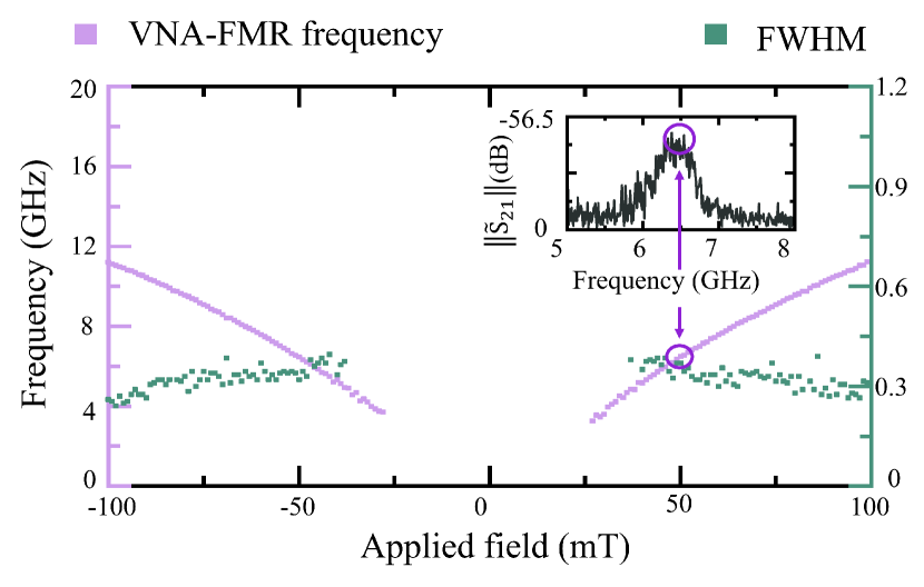
Fig. 2 summarizes the results obtained by VNA-FMR. The resonant frequency of the acoustic spin wave (pink curve) of the dots evolves quasi-linearly with the applied field. The resonance has the classical Lorentzian line shape (inset in Fig. 2), with a full width at half maximum that is almost independent of the field, being for instance 370 MHz for an applied field of mT leading to a resonant frequency of GHz. The analysis of the linewidth using ref. 22 yields a Gilbert damping of , where is the gyromagnetic ratio.
Because of shape anisotropy, the uniform resonance of the dots differs from the uniform resonance of the stripe on which PSWS will be performed. Let us model this difference using the demagnetizing factors of our geometries . Using Eq. 11 of 23, the demagnetizing factors of each layer of the dot are . Using 24, the demagnetizing tensor of each layer of the stripe is . Since , is the easy axis and we can define a shape anisotropy field as . We also define the saturation fields and for saturation by fields in either the or the direction.
For a field of magnitude applied in the direction, the SAF stripe is in a scissors state with the layers’ magnetizations being:
| (1) |
Linearization of the equations of motions can be used to derive the frequency of the acoustic spin wave:
| (2) |
We have deduced from , , and Eq. 2. The expected uniform resonance frequencies of the magnetic stripes for an applied field mT is for instance GHz. The resonance frequencies and their linewidth are very similar to that of samples grown on non-piezoelectric substrates [25, 26]. This is a first indicating that high quality SAF can be grown also on piezoelectric substrates. Let us determine the spin wave dispersion relation and its field dependence to assess this statement in a more quantitative way.
IV Spin wave spectroscopy of the acoustic spin waves of the synthetic antiferromagnets
IV.1 Propagating spin wave measurements and methods
To get the dispersion relations, we performed propagating spin wave spectroscopy. We use the standard method and connect the two antennas A1 and A2 to the two ports of a calibrated VNA to measure the forward and backward transmission parameters for various applied field [Fig. 1(a)]. The SWs of SAF in this field configuration are known (and were checked) to be frequency-reciprocal [17]. The data processing meant to maximize the signal-to-noise ratio is carried out following the time-gating and field-differentiation methods detailed in refs. 27 and 18.
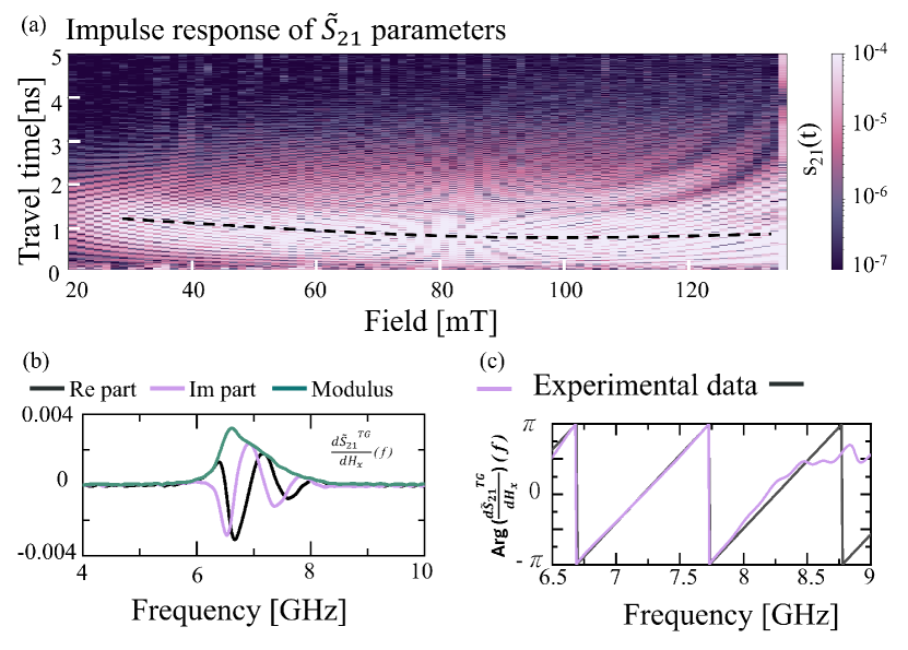
Fig 3.(a) shows the impulse response for a SW propagation distance m. The wavepackets of the acoustic SWs reach the second antenna in a travel time of typically ns. This group delay is essentially independent of the applied fields for fields inducing a scissor state 222For applied fields near and above saturation mT, the initially single wavepacket of the impulse response progressively splits into several separated wavepackets arriving at different ’s. This is indicative to the presence of several SW mode with different group velocities, most probably quantized in the width of the stripe [22]. [see the dashed line in Fig 3(a)]. This group delay yields a first estimate of the group velocity of km.s-1 and a first estimate of the attenuation length of m of the propagating acoustic spin waves.
Fig 3(b) shows a representative processed transmission spectrum around the frequency of the acoustic spin waves. The phase of the signal is reported in Fig 3(c). Transforming these phases into dispersion relations requires the modeling of the device’s response.
IV.2 Model of for reciprocal spin waves
For reciprocal waves with a -shaped dispersion relation, the contribution of the diagonal terms of the magnetic susceptibility to the forward transmission coefficient can be deduced from the sum of the experimental forward and reverse transmission coefficients (see the section IX.B of ref. 29):
| (3) |
We consider in addition the limit of an ultra-thin antenna placed close to the magnetic film. Using the formalism of ref. 29, we can reformulate an expression of for reciprocal SWs with a -shaped dispersion relation. Apart very near the uniform acoustic resonance, the scattering parameters can be expressed as [29]:
| (4) |
for , with a Lorentzian function centered at and of width related to the inverse attenuation length 333We neglect any variation of the attenuation length with the wavevector..
The propagation term is expressed using the function that expresses the phase rotation and the decay of the wave upon its propagation.
Using Eq. 2 and 4 and taking into consideration that , we can state that for the experimental data can be linked to the SW wavevector of the acoustic SW branch by:
| (5) |
with . The value of can be found from the frequency of the uniform mode () determined in section II. The equation 5 expresses that the phase of the field derivative of parameter evolves linearly with the wavevector with a distance independent correction term. This correction term can be rewritten as to evidence that it tends towards when working at frequencies . Fig. 3(c) shows the comparison of the experimental phase of the field derivative of with Eq. 5 for input values adjusted according to experimental measurements. The agreement is satisfactory and the dispersion relation can thus be deduced from a fit to Eq. 5.
IV.3 Dispersion relation of the acoustic spin waves
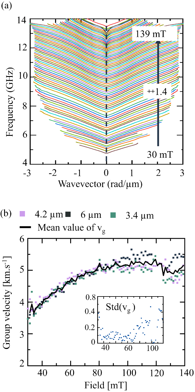
Fig. 4(a) gathers the dispersion relations of the acoustic SWs measured for applied field spanning from 30 mT up to 139 mT. This extends up to the maximum wavevector m that can be investigated with our antenna width. The part of the dispersion relations are constructed by symmetry.
For each applied field, the quasi-linear V-shape of the dispersion relation allows to define a characteristic group velocity. Fig. 4(b) reports the group velocity of SW deduced from linear fits done in the 0.7 to 1.3 rad/m interval of wavevector. For mT the group velocity is . It increases up to for mT. The group velocities deduced from samples with different propagation distances match together within a standard deviation of typically 200 m/s [inset of Fig. 4(b)]. This consistency among different devices is indicative of a good homogeneity of the magnetic properties despite their growth on non-standard substrates.
The group velocity is found to increase with the applied field until it saturates and decreases slightly for H mT. This behavior is in semi-quantitative agreement with the predictions for a 2-macrospin SAF [17], for which when , the group velocity is expected to be for (corresponding to the scissors state), and then to be slightly decreasing following for larger fields (corresponding to the saturated parallel state). This is an additional indication of proper synthetic antiferromagnetic behavior.
V Summary and concluding remarks
In summary, we have measured several metrics representative of the dynamical properties of synthetic antiferromagnets grown on LiNbO3 substrates and patterned into magnonic devices. The measurements include the uniform resonance of the acoustic spin waves, the dispersion relation of these spin waves, and consequently their group velocities and attenuation lengths. These metrics are indicative that the SAFs grown on LiNbO3 have very similar properties as the SAFs grown on standard non-piezoelectric substrates, for instance on silicon substrates [25, 17]. The new material platform shall enable to efficiently couple the magnetics degrees of freedom to the elastic ones, for instance to confer non-reciprocity to surface acoustic wave delay lines [31].
Acknowledgements.
This work was supported by the French RENATECH network, by the French National Research Agency (ANR) as part of the “Investissements d’Avenir” and France 2030 programs. This includes the SPICY project of the Labex NanoSaclay: ANR-10-LABX-0035, the MAXSAW project ANR-20-CE24-0025 and the PEPR SPIN projects ANR 22 EXSP 0008 and ANR 22 EXSP 0004. We acknowledge Aurélie Solignac for material growth and Loukas Kokkinos, Joo-Von Kim and Maryam Massouras for helpful comments.AUTHOR DECLARATIONS
Conflict of Interest
The authors have no conflicts to disclose.
Author Contributions
G. Y. Thiancourt: Data curation (lead); Formal analysis (lead); Writing– original draft (equal); Writing– review and editing (equal); Measurements (supporting); Investigation (equal). S. M. Ngom: Resources (equal); Investigation (equal); Measurements (equal). N. Bardou: Resources (equal). T. Devolder: Funding acquisition (lead); Investigation (equal); Measurements (equal); Writing– original draft (equal); Writing– review and editing (lead); Conceptualization (lead).
DATA AVAILABILITY
The data that support the findings of this study are available within the article from the corresponding author upon reasonable request.
REFERENCES
References
- Campbell [1998] C. Campbell, “Surface acoustic wave devices for mobile and wireless communications, four-volume set,” (Academic Press, 1998).
- Länge, Rapp, and Rapp [2008] K. Länge, B. E. Rapp, and M. Rapp, “Surface acoustic wave biosensors: a review,” Analytical and bioanalytical chemistry 391, 1509–1519 (2008).
- Pohl [2000] A. Pohl, “A review of wireless saw sensors,” IEEE transactions on ultrasonics, ferroelectrics, and frequency control 47, 317–332 (2000).
- Kittel [1958] C. Kittel, “Interaction of Spin Waves and Ultrasonic Waves in Ferromagnetic Crystals,” Physical Review 110, 836–841 (1958).
- Dreher et al. [2012] L. Dreher, M. Weiler, M. Pernpeintner, H. Huebl, R. Gross, M. S. Brandt, and S. T. B. Goennenwein, “Surface acoustic wave driven ferromagnetic resonance in nickel thin films: Theory and experiment,” Physical Review B 86, 134415 (2012).
- Küß et al. [2023] M. Küß, S. Glamsch, Y. Kunz, A. Hörner, M. Weiler, and M. Albrecht, “Giant Surface Acoustic Wave Nonreciprocity with Low Magnetoacoustic Insertion Loss in CoFeB/Ru/CoFeB Synthetic Antiferromagnets,” ACS Applied Electronic Materials 5, 5103–5110 (2023).
- Küß et al. [2021a] M. Küß, M. Heigl, L. Flacke, A. Hörner, M. Weiler, A. Wixforth, and M. Albrecht, “Nonreciprocal Magnetoacoustic Waves in Dipolar-Coupled Ferromagnetic Bilayers,” Physical Review Applied 15, 034060 (2021a).
- Küß et al. [2021b] M. Küß, M. Heigl, L. Flacke, A. Hefele, A. Hörner, M. Weiler, M. Albrecht, and A. Wixforth, “Symmetry of the Magnetoelastic Interaction of Rayleigh and Shear Horizontal Magnetoacoustic Waves in Nickel Thin Films on Li Ta O 3,” Physical Review Applied 15, 034046 (2021b).
- Huang et al. [2024] M. Huang, Y. Liu, W. Hu, Y. Wu, W. Wang, W. He, H. Zhang, and F. Bai, “Large nonreciprocity of shear-horizontal surface acoustic waves induced by a magnetoelastic bilayer,” Physical Review Applied 21, 014035 (2024).
- Xu et al. [2020] M. Xu, K. Yamamoto, J. Puebla, K. Baumgaertl, B. Rana, K. Miura, H. Takahashi, D. Grundler, S. Maekawa, and Y. Otani, “Nonreciprocal surface acoustic wave propagation via magneto-rotation coupling,” Science Advances 6, eabb1724 (2020).
- Yamamoto et al. [2022] K. Yamamoto, M. Xu, J. Puebla, Y. Otani, and S. Maekawa, “Interaction between surface acoustic waves and spin waves in a ferromagnetic thin film,” Journal of Magnetism and Magnetic Materials 545, 168672 (2022).
- Kwon et al. [2016] J. H. Kwon, J. Yoon, P. Deorani, J. M. Lee, J. Sinha, K.-J. Lee, M. Hayashi, and H. Yang, “Giant nonreciprocal emission of spin waves in ta/py bilayers,” Science Advances 2, e1501892 (2016).
- Stamps [1994] R. L. Stamps, “Spin configurations and spin-wave excitations in exchange-coupled bilayers,” Physical Review B 49, 339–347 (1994).
- Nörtemann, Stamps, and Camley [1993] F. C. Nörtemann, R. L. Stamps, and R. E. Camley, “Microscopic calculation of spin waves in antiferromagnetically coupled multilayers: Nonreciprocity and finite-size effects,” Physical Review B 47, 11910–11923 (1993).
- Ishibashi et al. [2020] M. Ishibashi, Y. Shiota, T. Li, S. Funada, T. Moriyama, and T. Ono, “Switchable giant nonreciprocal frequency shift of propagating spin waves in synthetic antiferromagnets,” Science Advances 6, eaaz6931 (2020).
- Gallardo et al. [2019] R. Gallardo, T. Schneider, A. Chaurasiya, A. Oelschlägel, S. Arekapudi, A. Roldán-Molina, R. Hübner, K. Lenz, A. Barman, J. Fassbender, J. Lindner, O. Hellwig, and P. Landeros, “Reconfigurable Spin-Wave Nonreciprocity Induced by Dipolar Interaction in a Coupled Ferromagnetic Bilayer,” Physical Review Applied 12, 034012 (2019).
- Millo et al. [2023] F. Millo, J.-P. Adam, C. Chappert, J.-V. Kim, A. Mouhoub, A. Solignac, and T. Devolder, “Unidirectionality of spin waves in synthetic antiferromagnets,” Physical Review Applied 20, 054051 (2023).
- Thiancourt et al. [2024] G. Thiancourt, S. Ngom, N. Bardou, and T. Devolder, “Unidirectional spin waves measured using propagating-spin-wave spectroscopy,” Physical Review Applied 22, 034040 (2024).
- Mouhoub et al. [2023] A. Mouhoub, F. Millo, C. Chappert, J.-V. Kim, J. Létang, A. Solignac, and T. Devolder, “Exchange energies in CoFeB/Ru/CoFeB synthetic antiferromagnets,” Physical Review Materials 7, 044404 (2023).
- Bilzer et al. [2007] C. Bilzer, T. Devolder, P. Crozat, C. Chappert, S. Cardoso, and P. Freitas, “Vector network analyzer ferromagnetic resonance of thin films on coplanar waveguides: Comparison of different evaluation methods,” Journal of applied physics 101 (2007).
- Note [1] The geometry were chosen to reduce the effect of shape anisotropy.
- Devolder et al. [2022] T. Devolder, S.-M. Ngom, A. Mouhoub, J. Letang, J.-V. Kim, P. Crozat, J.-P. Adam, A. Solignac, and C. Chappert, “Measuring a population of spin waves from the electrical noise of an inductively coupled antenna,” Physical Review B 105, 214404 (2022).
- Beleggia, De Graef, and Millev [2006] M. Beleggia, M. De Graef, and Y. Millev, “The equivalent ellipsoid of a magnetized body,” Journal of Physics D: Applied Physics 39, 891 (2006).
- Aharoni [1998] A. Aharoni, “Demagnetizing factors for rectangular ferromagnetic prisms,” Journal of applied physics 83, 3432–3434 (1998).
- Seeger et al. [2023] R. L. Seeger, F. Millo, A. Mouhoub, G. de Loubens, A. Solignac, and T. Devolder, “Inducing or suppressing the anisotropy in multilayers based on CoFeB,” Physical Review Materials 7, 054409 (2023).
- Wojewoda et al. [2023] O. Wojewoda, J. Holobrádek, D. Pavelka, E. Pribytova, J. Krčma, J. Klíma, J. Michalička, T. Lednický, A. V. Chumak, and M. Urbánek, “Unidirectional propagation of zero-momentum magnons,” (2023), arXiv:2311.10044 [cond-mat].
- Devolder et al. [2021] T. Devolder, G. Talmelli, S. M. Ngom, F. Ciubotaru, C. Adelmann, and C. Chappert, “Measuring the dispersion relations of spin wave bands using time-of-flight spectroscopy,” Physical Review B 103, 214431 (2021).
- Note [2] For applied fields near and above saturation mT, the initially single wavepacket of the impulse response progressively splits into several separated wavepackets arriving at different ’s. This is indicative to the presence of several SW mode with different group velocities, most probably quantized in the width of the stripe [22].
- Devolder [2023] T. Devolder, “Propagating-spin-wave spectroscopy using inductive antennas: Conditions for unidirectional energy flow,” Physical Review Applied 20, 054057 (2023).
- Note [3] We neglect any variation of the attenuation length with the wavevector.
- Verba, Tiberkevich, and Slavin [2019] R. Verba, V. Tiberkevich, and A. Slavin, “Wide-band nonreciprocity of surface acoustic waves induced by magnetoelastic coupling with a synthetic antiferromagnet,” Physical Review Applied 12, 054061 (2019).