ORB-SLAM3AB: Augmenting ORB-SLAM3 to Counteract Bumps with Optical Flow Inter-frame Matching
††thanks: This work was supported by the National Science Foundation of China 62271392, Shaanxi Innovation Team 2023CXTD04. Corresponding author: Chen He(chenhe@nwu.edu.cn).
1These authors contribute equally to this paper and should be considered as co-first author.
Abstract
This paper proposes an enhancement to the ORB-SLAM3 algorithm, tailored for applications on rugged road surfaces. Our improved algorithm adeptly combines feature point matching with optical flow methods, capitalizing on the high robustness of optical flow in complex terrains and the high precision of feature points on smooth surfaces. By refining the inter-frame matching logic of ORB-SLAM3, we have addressed the issue of frame matching loss on uneven roads. To prevent a decrease in accuracy, an adaptive matching mechanism has been incorporated, which increases the reliance on optical flow points during periods of high vibration, thereby effectively maintaining SLAM precision. Furthermore, due to the scarcity of multi-sensor datasets suitable for environments with bumpy roads or speed bumps, we have collected LiDAR and camera data from such settings. Our enhanced algorithm, ORB-SLAM3AB, was then benchmarked against several advanced open-source SLAM algorithms that rely solely on laser or visual data. Through the analysis of Absolute Trajectory Error (ATE) and Relative Pose Error (RPE) metrics, our results demonstrate that ORB-SLAM3AB achieves superior robustness and accuracy on rugged road surfaces.
Index Terms:
Bumpy Roads, Visual SLAM, Optical Flow, Inter-Frame Matching.I Introduction
SLAM (Simultaneous Localization and Mapping) is crucial for robotics and autonomous driving, providing essential capabilities for accurate navigation and environment mapping [1, 2, 3, 4, 5, 6, 7]. SLAM systems are mainly categorized into laser-based and visual SLAM.[8, 9, 10, 11, 12, 13, 14, 15, 16, 17, 18, 19] Laser SLAM methods, such as Livox-SLAM [20], R3LIVE [21], and CT-ICP [22], are known for their stability and accuracy. In contrast, visual SLAM methods, including ORB-SLAM3 [23] and VINS-Fusion [24], utilize texture information and techniques like feature matching and optical flow for high-precision localization and mapping.[25]
The origins of pure visual SLAM can be traced back to Davison’s Mono SLAM[26] in 2007. Significant advancements were made between 2015 and 2017 when Mur-Artal and his colleagues developed ORB-SLAM[27] and ORB-SLAM2 [28]. In 2016, J. Engel, V. Koltun and D. Cremers proposed Direct Sparse Odometry[29]. In 2021, Carlos Campos, Richard Elvira, and their colleagues introduced ORB-SLAM3, which accommodates different types of cameras and enhances pose estimation, further advancing the development of visual SLAM technology.
Among these algorithms, only a few, such as ORB-SLAM, support high-precision monocular camera SLAM, and most of them do not. Moreover, these monocular SLAM algorithms have neglected the research and development of robustness against bumpy ground. In 2024, Zhang Xiao and Li Shuaixin [30] proposed SL-SLAM, replacing traditional feature point selection and matching with deep learning techniques. However, this paper has not yet been published or had its code made public.
The work most closely related to ours is the ORB-SLAM2S[31]: A Fast ORB-SLAM2 System with Sparse Optical Flow Tracking proposed by Y. Diao, R. Cen, and F. Xue in 2021. However, their method focuses on improving the running speed through optical flow without enhancing the accuracy of SLAM in bumpy scenarios. Moreover, they use optical flow for non-keyframes and feature point methods for keyframes, which is significantly different from our designed integrated approach. In contrast, our algorithm enhances the robustness and precision of SLAM during bumpy conditions and has also been compared with laser SLAM on the same route.
In 2023, Zhao Tong and He Junxiang [32] introduced a dataset focused on road surface information, along with auxiliary algorithms for intelligent driving. In 2024 [33], Zhao Tong and Xie Yichen released the RSRD dataset, emphasizing complex road conditions with LiDAR and visual sensor data. However, datasets aimed at detecting ground unevenness pose significant challenges when used for SLAM.
This paper proposes a method that enhances the robustness and accuracy of ORB-SLAM3 under monocular conditions by integrating frame-to-frame matching based on optical flow with its existing feature-based approach. Using an adaptive algorithm to manage optical flow features, our approach improves ORB-SLAM3’s performance on bumpy roads. [34, 35, 36, 37, 38, 39, 40, 41]The comparison results with various monocular SLAM, pure LiDAR SLAM, and LiDAR-IMU combined SLAM algorithms demonstrate the superior effectiveness of our proposed method.
Our main contributions are as follows:
-
1.
We enhanced ORB-SLAM3’s frame-to-frame matching by integrating optical flow techniques, overcoming the limitations of feature-based matching and boosting robustness in scenarios with bumps and sharp turns.
-
2.
We conducted a comprehensive comparative analysis of our improved algorithm with both laser-based and pure monocular SLAM methods. This included plotting trajectories and calculating both Absolute Trajectory Error (ATE) and Relative Pose Error (RPE), with results demonstrating that our method excels in environments with intense bumps and significantly enhances the accuracy of monocular SLAM.
-
3.
We collected data from low-speed robots and high-speed vehicles in bumpy and multi-speed-bump scenarios, providing a valuable resource for assessing SLAM performance under these challenging conditions.
II ORB-SLAM3AB Framework
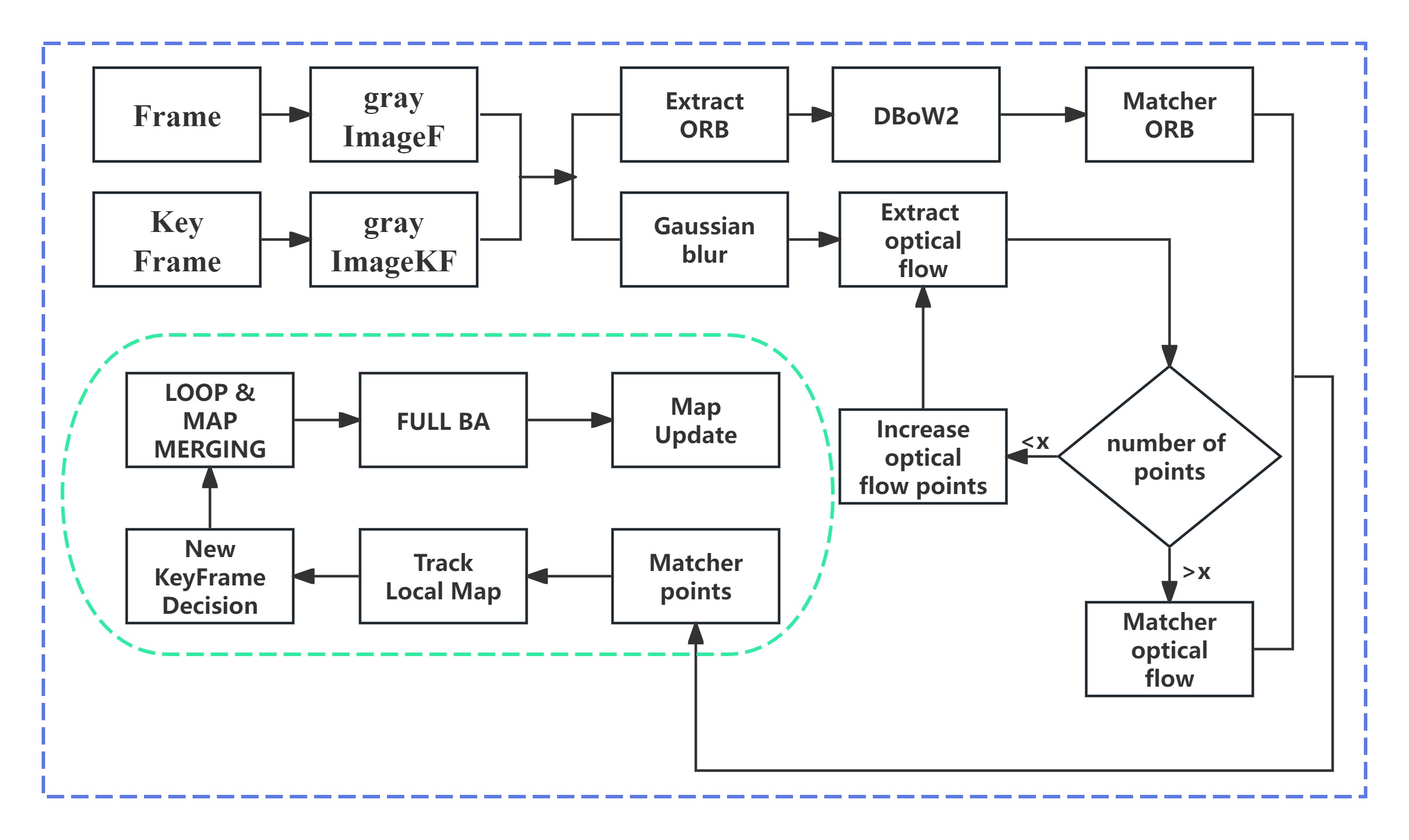
The ORB-SLAM3AB framework represents an advanced extension of the original ORB-SLAM3, designed to enhance the robustness and accuracy of monocular SLAM systems, particularly in challenging conditions such as bumpy roads. ORB-SLAM3AB improves the ORB-SLAM3 framework by incorporating enhanced feature point selection methods and modifying the feature point frame-to-frame matching strategy, addressing the limitations faced by visual SLAM in practical applications.For the process flow, please refer to Figure 1.
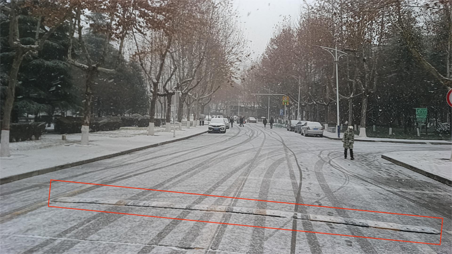

Multiple speed bump scenarios Bumpy road sections
II-A The System Overview
Feature points are prone to be lost in frame-to-frame matching due to complexity, while optical flow methods are less likely to lose track in frame-to-frame matching because they rely solely on photometric changes, but the accuracy of optical flow methods is often lower. Therefore, the organic combination of the two makes it possible to achieve high-precision monocular camera SLAM in bumpy scenarios.
ORB-SLAM3AB starts by processing monocular pinhole images, converting them to grayscale, and applying Gaussian denoising. The ORB algorithm extracts feature points, which are then used for optical flow-based frame-to-frame matching. To enhance robustness, we dynamically monitor the number of feature points matched between frames; if the match count is too low, we slightly increase the number of points selected by the optical flow method to ensure frame-to-frame matching can be performed even during bumps. When the match count is sufficient, we reduce the number of points selected by the optical flow method to increase the accuracy of SLAM.
It should be noted that in ORB-SLAM3, only increasing the number of feature points rather than the optical flow points can lead to unsuccessful frame-to-frame matching or significantly degrade the accuracy of SLAM due to an excessive increase in the number of points. Moreover, there are currently few monocular SLAM systems of this type available for comparative reference.
-
•
Image Preprocessing
The input keyframe image (imageKF) and the current frame image (imageF) undergo a color channel check followed by grayscale conversion. If the input images are in RGB format, a conversion function is employed to transform them into grayscale. Subsequently, Gaussian filtering is applied to the grayscale images to reduce noise and enhance the quality of the feature extraction.
-
•
Feature Point Extraction
Key points and descriptors are extracted from the grayscale images. The parameters of the feature point extractor, such as the number of detected points, scale factor, and the number of pyramid levels, are adjusted dynamically according to the detection strategy.
-
•
Dynamic Optical Flow Feature Point Detection and Matching
The detection of feature points using the optical flow method is based on the ORB operator. Initially, the number of optical flow points is set to half the number of feature points. If it is observed that the number of matched feature points in the current frame is insufficient during the subsequent matching process, the number of optical flow feature points is dynamically doubled. The specific values of these parameters should be adjusted according to the actual conditions, especially in scenarios with significant vibrations, where the number of selected feature points may need to be further increased.
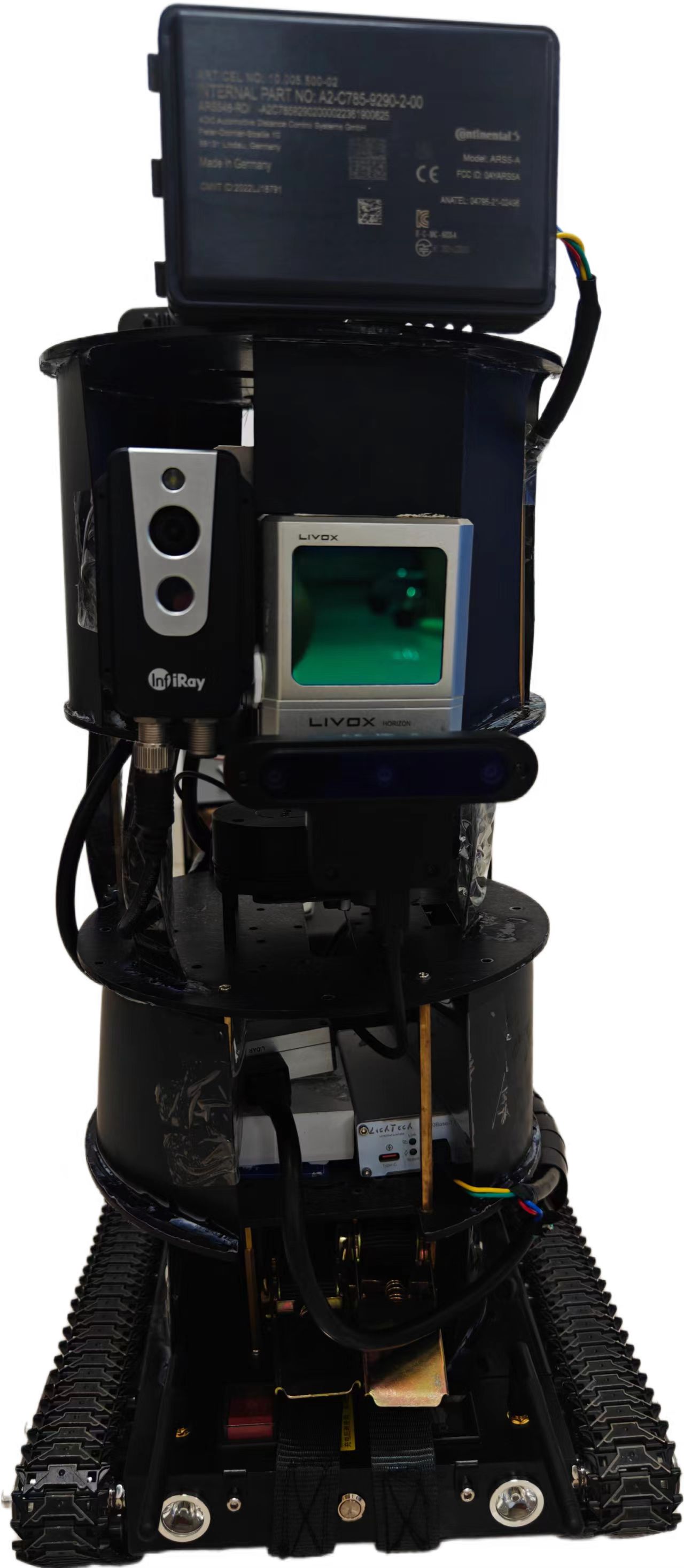
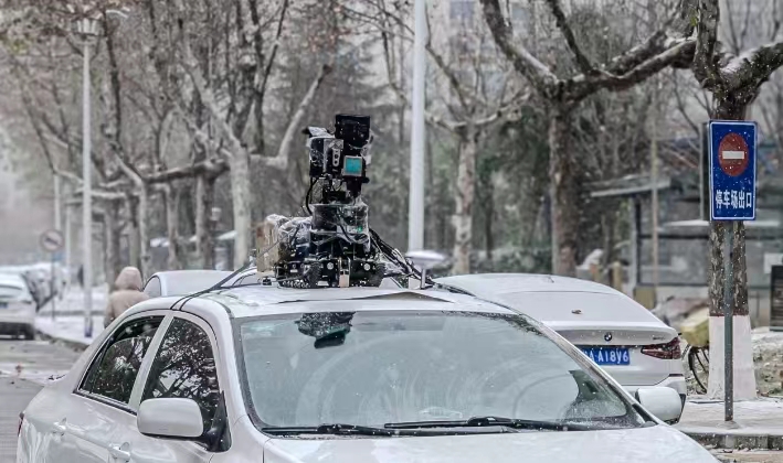
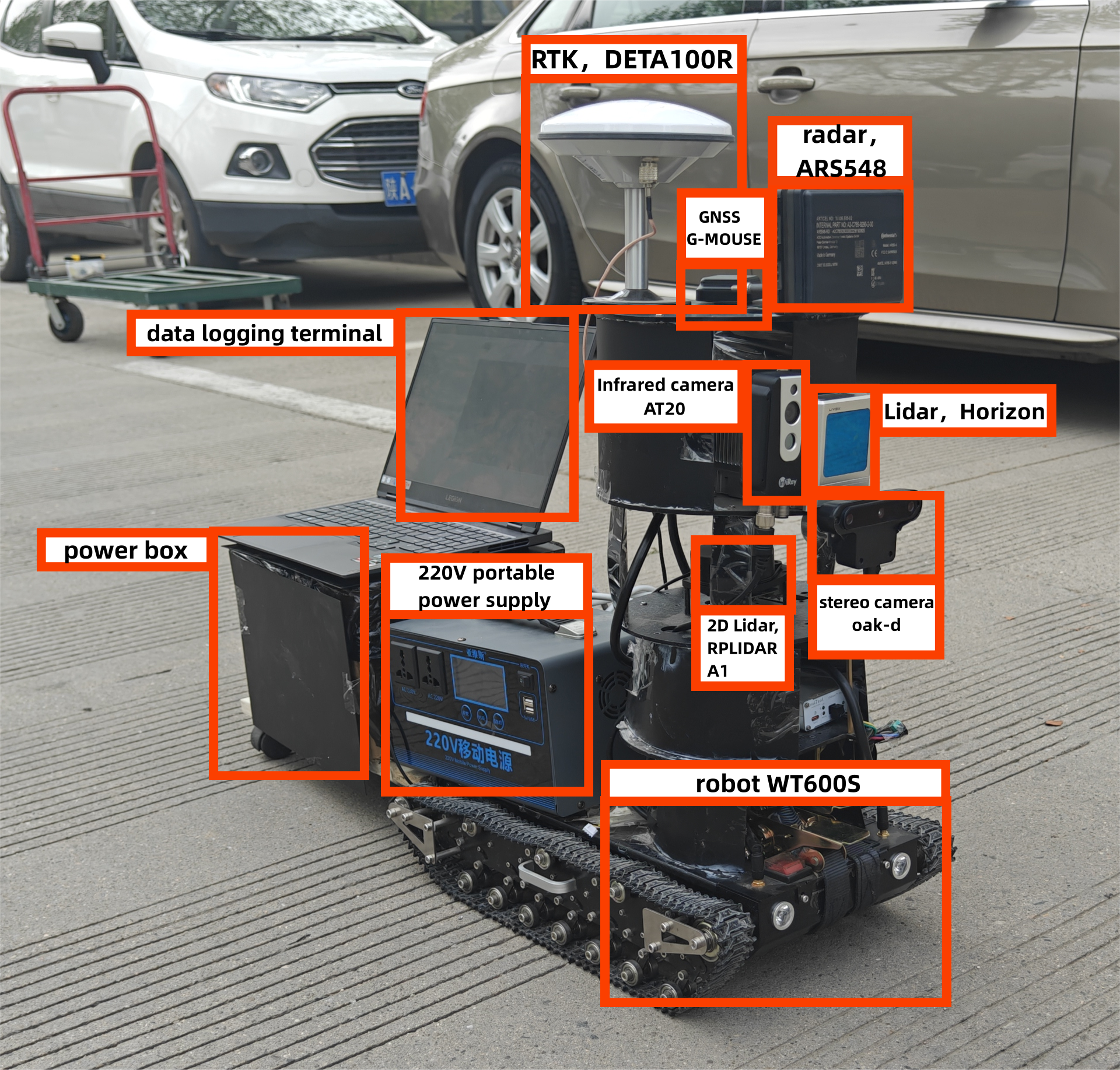
Figure 3: The diagram shows the actual ground robot and the sensor-equipped vehicle, with each component’s function clearly labeled. -
•
Rotation Consistency Check
A rotation consistency check is performed on the matched feature point pairs. The rotation angles of the feature points are statistically analyzed using the Histogram of Oriented Gradients (HOG) method, and potential erroneous matches are removed from the final results.
high speed bumps snowy day high speed bumps snowy night
low speed bumpy sunny day low speed bumpy sunny night
III Data Collection
Due to the rarity of multi-sensor datasets in bumpy scenarios, we designed and assembled a ground robot and integrated it into a vehicle using a detachable mounting system. The robot’s structure consists of five layers: the top three layers are equipped with various sensors, while the bottom two layers house interfaces, wiring, mobile power supplies, and computing units. As shown in Figure 3.
To achieve a comprehensive and diverse dataset, we employed both low-speed and high-speed data collection techniques. Our routes included a variety of scenarios, such as bumpy roads and flat roads with multiple speed bumps, and covered various weather conditions, including sunny, rainy, and snowy days, as well as different lighting conditions, including daytime and nighttime. This careful design ensures that our dataset captures a broad spectrum of speed, road, weather, and lighting conditions.
For low-speed data collection, we deployed ground robots to gather data from the same locations under different weather and lighting conditions. This approach allowed us to investigate the effects of specific conditions on sensor performance, with a particular focus on challenging bumpy road segments where loop closure detection was problematic due to their short distances.
In our high-speed data collection phase, we mounted the robot on the roof of a vehicle, maintaining consistent positions while varying weather and lighting conditions. This setup enabled us to collect high-speed data on roads with numerous speed bumps and to record data while navigating bumpy surfaces at high speeds.
We gathered approximately 1500 GB of image and point cloud data. This paper only utilized the bumpy scenarios from the dataset.
IV Evaluation
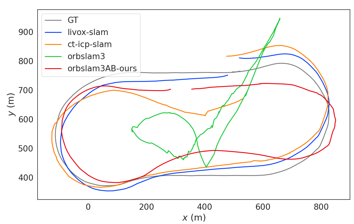
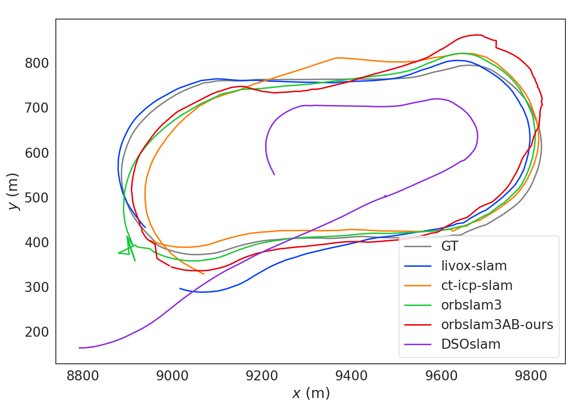
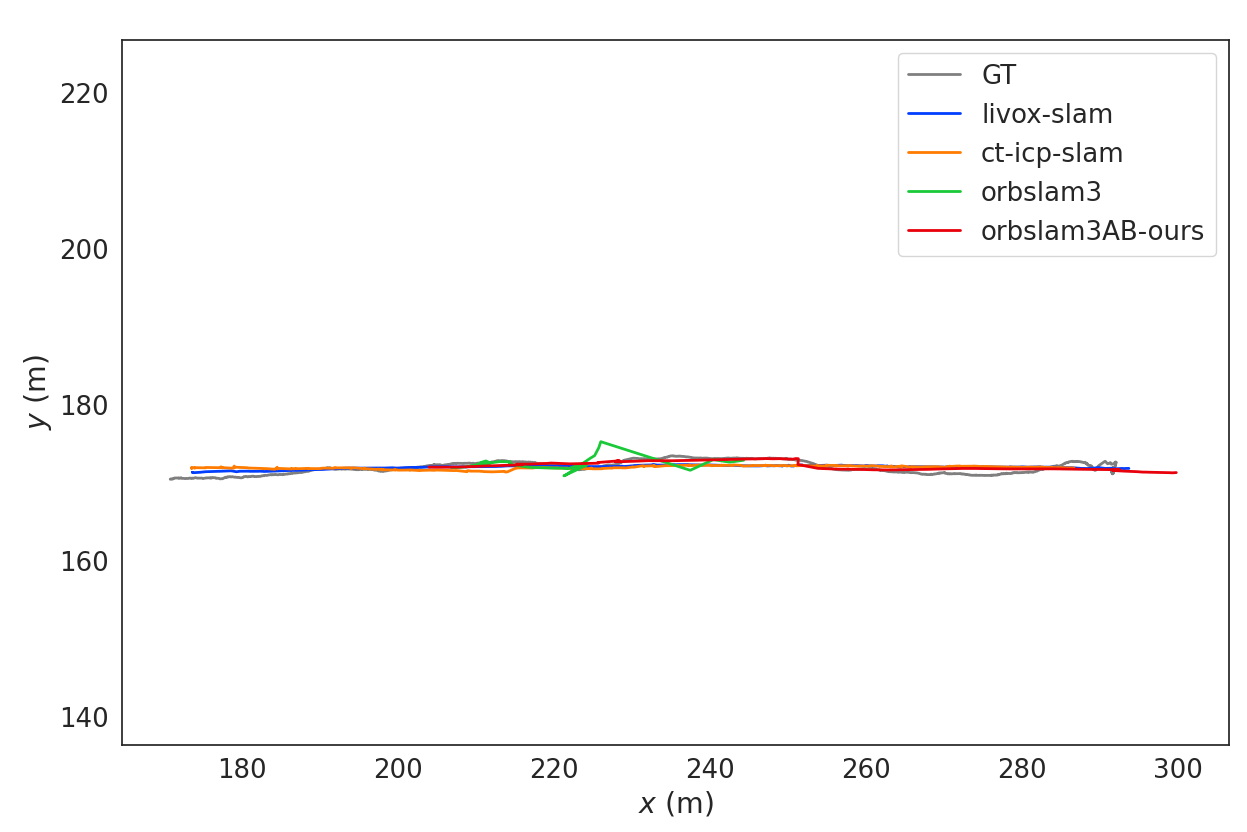
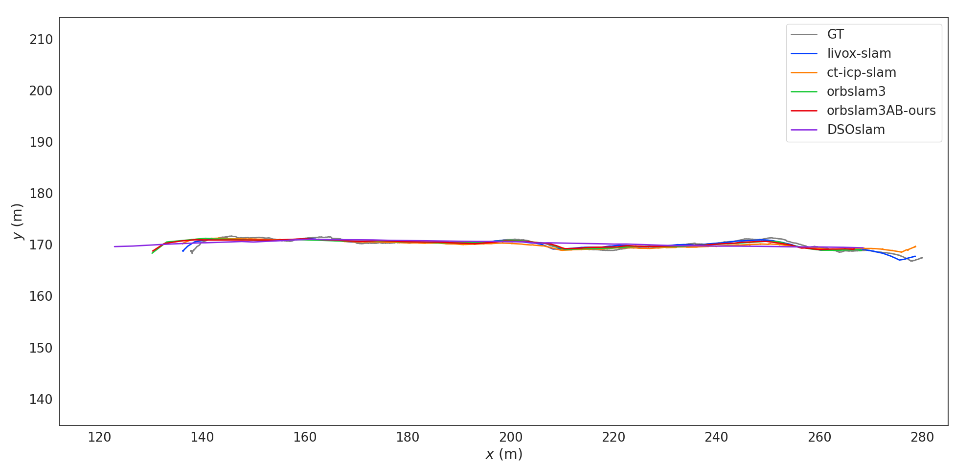
We applied various SLAM algorithms to the collected data across different scenarios. These included high-speed conditions with multiple speed bumps in sunny, rainy, and snowy weather, as well as low-speed conditions both during the day and night, with and without speed bumps. We evaluated laser-based SLAM and visual SLAM under varying weather conditions, and also assessed visual SLAM performance under different lighting and road conditions. The results were compared against ground truth, providing trajectory maps, Absolute Trajectory Error (ATE)[42, 43], and Relative Pose Error (RPE) [44, 45]. Detailed information about these test scenarios is presented in Tables 1 and Figure 4.
| Sequence | livox-slam | CT-ICP | DSO | ORB-SLAM3 | ORB-SLAM3AB(ours) | |||||
|---|---|---|---|---|---|---|---|---|---|---|
| ATE | RPE | ATE | RPE | ATE | RPE | ATE | RPE | ATE | RPE | |
| low-speed-bumpy- | ||||||||||
| sunny-day | 1.845 | 0.951 | 1.294 | 0.568 | x | x | x | x | 0.228 | 0.099 |
| low-speed-bumpy- | ||||||||||
| sunny-night | 1.901 | 0.960 | 1.852 | 0.686 | 0.110 | 0.121 | 0.039 | 0.041 | 0.038 | 0.040 |
| high-speed-bumps | ||||||||||
| snowy-day | 38.503 | 10.920 | 44.199 | 8.444 | 181.459 | 8.044 | 4.856 | 2.035 | 4.652 | 0.884 |
| high-speed-bumps | ||||||||||
| snowy-night | 33.675 | 12.819 | 53.614 | 7.300 | x | x | 7.643 | 0.700 | 1.791 | 0.283 |
Livox-SLAM, CT-ICP represent some of the most advanced laser-based SLAM algorithms available today. These algorithms deliver exceptional accuracy for large-scale SLAM tasks. Our analysis of ATE and RPE demonstrates that laser-based SLAM maintains robust performance over short, uneven terrain. Conversely, in long-distance scenarios with loop closures, the drift errors associated with LiDAR-based SLAM are substantially higher than those observed with visual SLAM methods.
ORB-SLAM3 is a well-established visual SLAM algorithm, known for its rapid response and accurate feature extraction using the ORB operator. However, its robustness significantly decreases under conditions of severe bumps or sharp turns. In high-speed snowy scenarios involving multiple speed bumps, excessive camera shake may lead to feature tracking failures, significant trajectory deviations, and anomalies in loop closure algorithms, resulting in strange-looking rendered images. Similarly, on continuous bumpy low-speed sunny days, the performance of visual SLAM is notably affected.
DSO is a monocular visual SLAM system known for its ability to overcome tracking scenarios with very little texture. This SLAM is more robust in mapping than ORB-SLAM, especially in areas with few features. However, it still exhibits low robustness or low accuracy in scenarios with speed bumps or continuous bumps. In high-speed snowy conditions, due to speed bumps encountered during turns and other reasons, its accuracy is significantly reduced. In high-speed snowy night scenarios, it even loses keyframe information directly, causing the algorithm to be unable to continue working. Similarly, during low-speed continuous bumpy days, the intense shaking of the robot makes feature point selection difficult, leading to an inability to complete the SLAM task.
We employed the improved ORB-SLAM3AB algorithm to test various scenarios, including low-speed bumpy roads during sunny days and nights, as well as high-speed roads with multiple speed bumps on snowy days. From the plotted trajectories, it can be seen that the improved algorithm’s tracks more closely match the ground truth. We calculated the corresponding ATE (Absolute Trajectory Error) and RPE (Relative Pose Error). Our algorithm effectively addresses the issue of poor inter-frame matching during bumps, and compared to laser-based SLAM and pure visual SLAM, the new algorithm exhibits lower ATE and RPE values. The experimental results demonstrate that our enhanced algorithm shows greater robustness and improved accuracy on bumpy roads.
V Reflection
Bumpy conditions can significantly degrade the accuracy of both visual SLAM and laser SLAM. Our algorithm leverages the precision of feature point methods and the robustness of optical flow methods to improve ORB-SLAM3 under pure visual conditions, ensuring that it can still complete mapping tasks with relatively high accuracy even in severe bump scenarios. However, introducing optical flow methods might reduce the precision of SLAM on smooth roads. A potential focus for future research could be how to increase robustness in bumpy scenarios without compromising, or even improving, the precision of SLAM on smooth roads. Additionally, investigating whether incorporating LiDAR data during severe bumps through sensor fusion can effectively enhance the robustness of the algorithm is also a direction for future study.
VI Conclusion
In this paper, we identified key issues with current visual SLAM systems, particularly the loss of frame-to-frame tracking under strong vibrations and rapid motion. Using ORB-SLAM3 as the framework, we leveraged the robustness of optical flow to increase the detection of flow points during heavy bumps, combining this with the accuracy of feature point methods, which significantly improved the performance of monocular visual SLAM. Due to the scarcity of public datasets that include LiDAR and camera data for speed bumps, continuous bumps, and day and night conditions, we conducted experiments on our self-collected dataset. The experiments demonstrated that our improved algorithm enhances the robustness and accuracy of pure visual SLAM in scenarios with speed bumps or continuous bumps. However, the algorithm still struggles with extremely rapid camera shake and vibrations. Future research will focus on further optimizing the system to address these challenges.
References
- [1] A. A. B. Pritsker, Introduction to Simulation and SLAM II. Halsted Press, 1984.
- [2] A. Singandhupe and H. M. La, “A review of slam techniques and security in autonomous driving,” in 2019 third IEEE international conference on robotic computing (IRC). IEEE, 2019.
- [3] C. Cadena et al., “Past, present, and future of simultaneous localization and mapping: Toward the robust-perception age,” IEEE Trans. Robot., vol. 32, no. 6, pp. 1309–1332, Dec. 2016.
- [4] J. Aulinas, Y. Petillot, J. Salvi, and X. Lladó, “The slam problem: a survey,” Artificial Intelligence Research and Development, pp. 363–371, 2008.
- [5] M. G. Dissanayake, P. Newman, S. Clark, H. F. Durrant-Whyte, and M. Csorba, “A solution to the simultaneous localization and map building (slam) problem,” IEEE Transactions on robotics and automation, vol. 17, no. 3, pp. 229–241, 2001.
- [6] J. Engel, T. Schöps, and D. Cremers, “Lsd-slam: Large-scale direct monocular slam,” in European conference on computer vision. Springer, 2014, pp. 834–849.
- [7] S. Kohlbrecher, O. Von Stryk, J. Meyer, and U. Klingauf, “A flexible and scalable slam system with full 3d motion estimation,” in 2011 IEEE international symposium on safety, security, and rescue robotics. IEEE, 2011, pp. 155–160.
- [8] A. Tourani, H. Bavle, J. L. Sanchez-Lopez, and H. Voos, “Visual slam: What are the current trends and what to expect?” Sensors, vol. 22, no. 23, p. 9297, Nov. 2022. [Online]. Available: http://dx.doi.org/10.3390/s22239297
- [9] L. Huang, “Review on lidar-based slam techniques,” in 2021 International Conference on Signal Processing and Machine Learning (CONF-SPML). IEEE, 2021, pp. 163–168.
- [10] A. Singandhupe and H. M. La, “A review of slam techniques and security in autonomous driving,” in 2019 third IEEE international conference on robotic computing (IRC). IEEE, 2019, pp. 602–607.
- [11] I. A. Kazerouni, L. Fitzgerald, G. Dooly, and D. Toal, “A survey of state-of-the-art on visual slam,” Expert Systems with Applications, vol. 205, p. 117734, 2022.
- [12] A. Macario Barros, M. Michel, Y. Moline, G. Corre, and F. Carrel, “A comprehensive survey of visual slam algorithms,” Robotics, vol. 11, no. 1, p. 24, 2022.
- [13] S. Sumikura, M. Shibuya, and K. Sakurada, “Openvslam: A versatile visual slam framework,” in Proceedings of the 27th ACM International Conference on Multimedia, 2019, pp. 2292–2295.
- [14] H. Strasdat, J. M. Montiel, and A. J. Davison, “Visual slam: why filter?” Image and Vision Computing, vol. 30, no. 2, pp. 65–77, 2012.
- [15] K. Yousif, A. Bab-Hadiashar, and R. Hoseinnezhad, “An overview to visual odometry and visual slam: Applications to mobile robotics,” Intelligent Industrial Systems, vol. 1, no. 4, pp. 289–311, 2015.
- [16] C. Debeunne and D. Vivet, “A review of visual-lidar fusion based simultaneous localization and mapping,” Sensors, vol. 20, no. 7, p. 2068, 2020.
- [17] D. Cattaneo, M. Vaghi, and A. Valada, “Lcdnet: Deep loop closure detection and point cloud registration for lidar slam,” IEEE Transactions on Robotics, vol. 38, no. 4, pp. 2074–2093, 2022.
- [18] X. Chen, T. Läbe, A. Milioto, T. Röhling, O. Vysotska, A. Haag, J. Behley, and C. Stachniss, “Overlapnet: Loop closing for lidar-based slam,” arXiv preprint arXiv:2105.11344, 2021.
- [19] C. Park, P. Moghadam, S. Kim, A. Elfes, C. Fookes, and S. Sridharan, “Elastic lidar fusion: Dense map-centric continuous-time slam,” in 2018 IEEE International Conference on Robotics and Automation (ICRA). IEEE, 2018, pp. 1206–1213.
- [20] J. Lin and F. Zhang, “Loam livox: A fast, robust, high-precision lidar odometry and mapping package for lidars of small fov,” in 2020 IEEE International Conference on Robotics and Automation (ICRA). IEEE, 2020.
- [21] ——, “R 2 live: A robust, real-time, lidar-inertial-visual tightly-coupled state estimator and mapping,” IEEE Robotics and Automation Letters, vol. 6, no. 4, pp. 7469–7476, 2021.
- [22] P. Dellenbach et al., “Ct-icp: Real-time elastic lidar odometry with loop closure,” in 2022 International Conference on Robotics and Automation (ICRA). IEEE, 2022.
- [23] C. Campos and J. D. Tardós, “Orb-slam3: An accurate open-source library for visual, visual–inertial, and multimap slam,” IEEE Transactions on Robotics, vol. 37, no. 6, pp. 1874–1890, 2021.
- [24] T. Qin, S. Cao, J. Pan, and S. Shen, “A general optimization-based framework for global pose estimation with multiple sensors,” arXiv preprint arXiv:1901.03642, 2019.
- [25] T. Taketomi, H. Uchiyama, and S. Ikeda, “Visual slam algorithms: A survey from 2010 to 2016,” IPSJ transactions on computer vision and applications, vol. 9, pp. 1–11, 2017.
- [26] A. J. Davison, I. D. Reid, N. D. Molton, and O. Stasse, “Monoslam: Real-time single camera slam,” IEEE transactions on pattern analysis and machine intelligence, vol. 29, no. 6, pp. 1052–1067, 2007.
- [27] R. Mur-Artal, J. M. M. Montiel, and J. D. Tardos, “Orb-slam: a versatile and accurate monocular slam system,” IEEE transactions on robotics, vol. 31, no. 5, pp. 1147–1163, 2015.
- [28] R. Mur-Artal and J. D. Tardós, “Orb-slam2: An open-source slam system for monocular, stereo, and rgb-d cameras,” IEEE transactions on robotics, vol. 33, no. 5, pp. 1255–1262, 2017.
- [29] J. Engel, V. Koltun, and D. Cremers, “Direct sparse odometry,” in arXiv:1607.02565, July 2016.
- [30] Z. Xiao and S. Li, “Sl-slam: A robust visual-inertial slam based deep feature extraction and matching,” arXiv preprint arXiv:2405.03413, 2024.
- [31] Y. Diao, R. Cen, F. Xue, and X. Su, “Orb-slam2s: A fast orb-slam2 system with sparse optical flow tracking,” in 2021 13th International Conference on Advanced Computational Intelligence (ICACI). IEEE, 2021, pp. 160–165.
- [32] T. Zhao, J. He, J. Lv, D. Min, and Y. Wei, “A comprehensive implementation of road surface classification for vehicle driving assistance: Dataset, models, and deployment,” IEEE Transactions on Intelligent Transportation Systems, vol. 24, no. 8, pp. 8361–8370, 2023.
- [33] T. Zhao, Y. Xie, M. Ding, L. Yang, M. Tomizuka, and Y. Wei, “A road surface reconstruction dataset for autonomous driving,” Scientific data, vol. 11, no. 1, p. 459, 2024.
- [34] F. H. Post, B. Vrolijk, H. Hauser, R. S. Laramee, and H. Doleisch, “The state of the art in flow visualisation: Feature extraction and tracking,” in Computer Graphics Forum, vol. 22, no. 4. Wiley Online Library, 2003, pp. 775–792.
- [35] S. S. Beauchemin and J. L. Barron, “The computation of optical flow,” ACM computing surveys (CSUR), vol. 27, no. 3, pp. 433–466, 1995.
- [36] J. L. Barron, D. J. Fleet, S. S. Beauchemin, and T. Burkitt, “Performance of optical flow techniques,” in Proceedings 1992 IEEE Computer Society Conference on Computer Vision and Pattern Recognition. IEEE Computer Society, 1992, pp. 236–237.
- [37] B. K. Horn and B. G. Schunck, “Determining optical flow,” Artificial intelligence, vol. 17, no. 1-3, pp. 185–203, 1981.
- [38] D. Sun, S. Roth, and M. J. Black, “Secrets of optical flow estimation and their principles,” in 2010 IEEE computer society conference on computer vision and pattern recognition. IEEE, 2010, pp. 2432–2439.
- [39] S. A. K. Tareen and Z. Saleem, “A comparative analysis of sift, surf, kaze, akaze, orb, and brisk,” in 2018 International conference on computing, mathematics and engineering technologies (iCoMET). IEEE, 2018, pp. 1–10.
- [40] H.-J. Chien, C.-C. Chuang, C.-Y. Chen, and R. Klette, “When to use what feature? sift, surf, orb, or a-kaze features for monocular visual odometry,” in 2016 International Conference on Image and Vision Computing New Zealand (IVCNZ). IEEE, 2016, pp. 1–6.
- [41] S. Gupta, M. Kumar, and A. Garg, “Improved object recognition results using sift and orb feature detector,” Multimedia Tools and Applications, vol. 78, no. 23, pp. 34 157–34 171, 2019.
- [42] Z. Zhang and D. Scaramuzza, “A tutorial on quantitative trajectory evaluation for visual (-inertial) odometry,” in 2018 IEEE/RSJ International Conference on Intelligent Robots and Systems (IROS). IEEE, 2018, pp. 7244–7251.
- [43] E. J. Shamwell, S. Leung, and W. D. Nothwang, “Vision-aided absolute trajectory estimation using an unsupervised deep network with online error correction,” in 2018 IEEE/RSJ International Conference on Intelligent Robots and Systems (IROS). IEEE, 2018, pp. 2524–2531.
- [44] D. Prokhorov et al., “Measuring robustness of visual slam,” in 2019 16th International conference on machine vision applications (MVA). IEEE, 2019.
- [45] A. Angelidis and G.-C. Vosniakos, “Prediction and compensation of relative position error along industrial robot end-effector paths,” International journal of precision engineering and manufacturing, vol. 15, pp. 63–73, 2014.