Enhancement of dynamical coupling in artificial spin-ice systems by incorporating perpendicularly magnetized ferromagnetic matrix
Abstract
Artificial spin-ice systems, consisting of arrays of interacting ferromagnetic nanoelements, offer a versatile platform for reconfigurable magnonics with potential in GHz logic and neuromorphic computing. However, weak dipolar coupling between nanoelements severely limits their functionality. We numerically demonstrate a rich spin-wave spectrum in a square spin-ice structure immersed in a perpendicularly magnetized ferromagnetic matrix, which is different from a single spin-ice system. We observe a strong magnon-magnon coupling between the bulk second-order mode of the nanoelements and the fundamental mode of the matrix, supported by a pronounced anticrossing frequency gap. We show that, in addition to the dipolar coupling, exchange interactions at the nanoelement-matrix interface play a crucial role in this hybridization. Furthermore, the strength of the coupling can be enhanced by almost 40% just by reconfiguring the magnetization at the vertices from low-energy to high-energy monopole states. These results open the way to exploit artificial spin-ice systems for magnonic applications, taking advantage of the strong coupling and vertex-dependent dynamics.
I Introduction
Spin waves (SWs) are being explored for information transfer and processing in reconfigurable systems [1, 2]. They offer numerous advantages as data carriers, including reduced waste heat, tunable wavelengths down to sub-100 nm, frequencies ranging from below 1 GHz to tens of THz, and coherent coupling between different SW modes (magnons), photons, and phonons [3, 4, 5, 6]. Recently, reconfigurable magnonic crystals (RMCs), a class of metamaterials, in which the magnetization state can be changed, have made significant progress in achieving useful functionalities, in particular, for low-power computing, high-speed data processing, and advanced signal processing [7, 1, 8, 9, 10, 11, 12].
Artificial spin ice (ASI) systems, which can be considered as a subset of RMCs, feature inter-element couplings, primarily governed by long-range magnetic dipole interactions, which introduce geometrical frustration of the magnetization orientation in a mono-domain ferromagnetic nanoelments [13, 14, 15, 16]. As a result, the ASI system exhibits a rich variety of magnetic states and behaviors, including the formation of magnetic monopole-like excitations, extensive degeneracy, Coulomb phase and other complex phenomena [17, 18, 19, 20, 21]. The resulting emergent magnetic monopoles and ground state magnetization degeneracy, combined with exceptional flexibility in lattice design, make ASI a promising candidate for reprogrammable functional magnonic devices [22, 23, 24]. Thus, magnetic resonances and SW confined modes have been investigated in a variety of ASI systems in recent times [8, 9, 25]. Collective SW behaviour, mode hybridization, and nonlinear multimagnon scattering have been demonstrated, highlighting the intricate and dynamic nature of these systems [26, 27, 28, 29, 30, 31, 32]. The evolution of mode dynamics from the ground state to charged monopole states has also been of particular interest, as investigated in depth in Ref. [26].
Moreover, recent research suggests that exploring the range of accessible microstates and unique magnonic behaviors in ASI systems can significantly enhance the capabilities for reservoir computing, a subset of neuromorphic computing [33]. In addition to the accessible magnetic states, the ASIs are also explored for magnon-magnon coupling [34, 35, 36, 37, 38]. Specifically, mode hybridizations and frequency anticrossing are highly dependent on vertex types in square ice configurations, with charged monopole vertices exhibiting an enhanced frequency gap [39]. Some studies have tuned magnon coupling strength in ASI through controlled dipolar interactions, interlayer exchange interaction, and modifying external magnetic field direction [37]. However, to date, ASI systems, even when based on multilayer ferromagnetic nano-elements, rely on a relatively weak, long-range dipolar coupling between them, which severely limits the strength of the coupling and the feasibility of the system to transfer information between discrete islands. These limit the potential applications of ASIs in magnonics.
Our previous experimental and numerical studies have demonstrated the SW dynamics in two-dimensional magnonic antidot lattice (ADLs) based on perpendicular magnetic anisotropy (PMA) multilayers [40, 41, 42]. In these systems, when the PMA multilayer is patterned with Ga ions (in a FIB process), the PMA at the edges of the antidots is significantly reduced. This results in the formation of in-plane magnetized edges around the antidots, which are immersed in an out-of-plane magnetized matrix, in remanence, or small biased magnetic fields. The recent results indicate a rather strong magnon-magnon coupling between the azimuthal SW mode in the rim and the SW mode of the PMA matrix. Interestingly, the exchange interactions at the rim-PMA matrix interface have been identified as a key source of this coupling. The coexistence of two magnetically different, in-plane and out-of-plane magnetized, but strongly coupled subsystems in the multilayer opens the possibility of creating a novel type of ASI system. Therefore, we propose to use square lattices of nanoelements with reduced PMA immersed in the metallic multilayer with interface-induced PMA as an ASI.
We investigate the SW dynamics in in-plane magnetized ferromagnetic nanoelements forming a square lattice ASI (SSI), and integrated with perpendicularly magnetized Co/Pd multilayer (SSI-PMA) using micromagnetic simulations. We observe rich and distinct magnonic spectra in SSI-PMA structures compared to the standalone SSI system. In particular, the second-order bulk mode of the SSI nanoelement hybridizes with the fundamental bulk mode of the PMA matrix, resulting in significant anticrossing frequency gaps and thus strong magnon-magnon coupling. By varying the vertex gap between the nanoelements and adjusting the effective thickness of the multilayer, the coupling strength can be tuned. Importantly, our results reveal that mode hybridization and coupling strength depend on the vertex type of the SSI, allowing the variety of magnetization states in ASIs to be exploited to control magnon-magnon coupling and collective SW dynamics. The proposed system can be fabricated experimentally by controlled focused ion irradiation of ferromagnetic multilayers with PMA and the predicted properties can be measured with a standard broadband ferromagnetic resonance technique. We have therefore shown that the study of PMA-based ASI systems is an important and compelling direction for future research in magnetism and magnonics.
II Structure and Methods
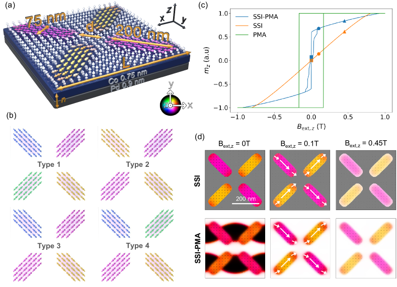
Our artificial SSI-PMA system is composed of in-plane magnetized nanoelements of elongated shape with rounded corners, with dimensions of 200 nm length and 75 nm width, immersed in a perpendicularly magnetized matrix, as schematically shown in Fig. 1(a). These dimensions are chosen to closely correspond to those in previous SSI studies [30, 26, 29]. Initially, the lattice constant of the structure is set to 424.26 nm (diagonal length 600 nm), and a vertex gap between nanoelements is 100 nm. The whole film is composed of a multilayer consisting of Co (0.75 nm) and Pd (0.9 nm), with total thickness of 13.2 nm. However, in micromagnetic simulation, this stack is represented as a single ferromagnetic layer with effective properties [41, 40]. The effective material parameters chosen for the Co/Pd multilayer are as follows: exchange constant pJ/m, and saturation magnetization kA/m. For clarity of the spectra in most simulations, we assume a negligible Gilbert damping constant , for selected cases a realistic value is assumed. We assume a bulk magnetic anisotropy, with constant J/m³ along the axis in the matrix region, while it is set to 0 in the in-plane magnetized SSI nanoelements.
The micromagnetic simulations are performed using own version of [43], called [44]. More detailed description of simulation procedures can be found in the Supplemental Information Sec. I.
III Results and Discussion
III.1 Artificial square spin ice and PMA
Our SSI-PMA consists of periodic vortices, connected by a PMA material, where four nanoelement magnetic moments converge. These vertices are generally categorized into four different types based on their magnetization configurations, as illustrated in Fig. 1(b). Each nanoelement in the vertex has two magnetization states that either point in or out. Out of the 16 possible configurations, 6 satisfy the two-in-two-out ice rule, corresponding to Type 1 and Type 2 vertices. The remaining configurations are classified as Type 3 or Type 4 vertices and host magnetic monopole charges, and , respectively. This is similar to the previously extensively studied square-lattice ASIs [22, 13]. To illustrate the novelty of the SSI-PMA system, we will compare its SW spectra with the system of the same in-plane nanoelements but without PMA matrix, which we will call the SSI system.
Figure 1(c) shows the simulated hysteresis loop for the SSI-PMA, SSI, and additionally for the homogeneous Co/Pd film with PMA (named as PMA, and having the same thickness as matrix in the SSI-PMA), with the magnetic field applied along the out-of-plane direction, and starting the simulations in full saturation with T. The PMA and SSI-PMA systems show behavior characteristics of easy-axis direction, while the SSI system exhibits a hard-axis type hysteresis loop. The large and different fields required for saturation of domains in SSI (0.80 T) and SSI-PMA (0.93 T) are due to the strong dipolar coupling between the in-plane nanoelements, and between nanoelements and PMA matrix, respectively. At remanence and field values up to the saturation, the in-plane nanoelements in both systems stabilize with Type 2 orientation of magnetization, as illustrated in Fig. 1(d) for , 0.1 and 0.45 T. Although the Type 1 state also satisfies the ice rule, it is difficult to achieve during remagnetization and is more easily achieved by thermal relaxation[22]. In contrast, the Type 2 state is more commonly observed during remagnetization in systems with short interelement distances between neighboring nanoelements, which leads to stronger dipolar interactions that favor this configuration. Thus in the following section, we will focus on the Type 2 configuration, and in Sec. III.4 we will extend our research with the other vertice types to study the influence of magnetic monopoles on SW spectra.
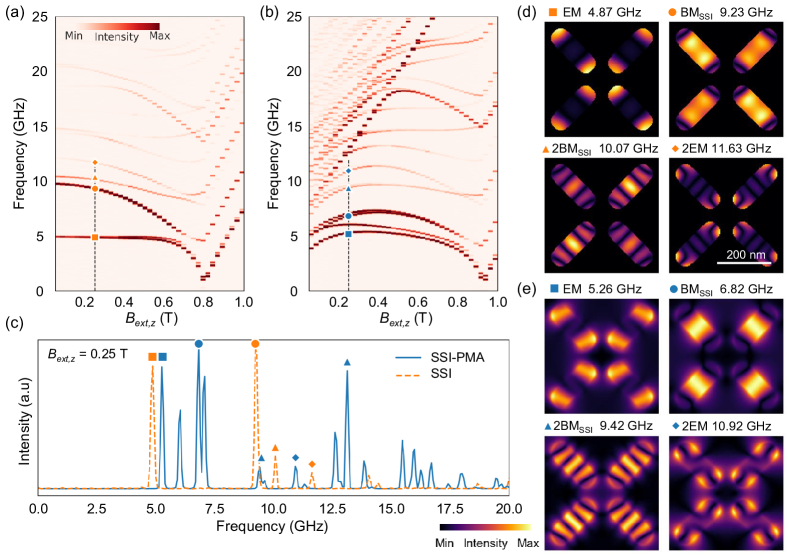
The SW characteristics of SSI and SSI-PMA systems were performed under an external out-of-plane magnetic field in the range of 0 to 1 T. The results are shown for both SSI [Fig. 2(a)] and SSI-PMA [Fig. 2(b)] systems, each with a vertex gap nm and nm (length along diagonal 600 nm). The color represents the SW mode intensity calculated as described in Sec. II. The SW spectra for the SSI and SSI-PMA structures at an arbitrarily chosen field value of 0.25 T, i.e., cross sections of the spectra in Fig. 2(a)-(b), are shown in Fig. 2(c). For completeness, the frequency spectrum of the PMA matrix with the holes instead of nanoelements under an external field is presented in Supplementary Information Sec. II. In the SSI system, for all modes, the frequency of the SWs decreases with increasing until saturation at 0.8 T. Two types of modes can be distinguished: Edge Modes (EMs) and Bulk Modes (). The EMs are localized at the ends of the nanoelements, where demagnetizing field is strongest, and are observed in the lower frequency region [26, 27]. The have amplitude concentrated at the center of the nanoelements. At higher frequencies there are also higher-order EMs and [27, 26, 45]. For instance, at 0.25 T, the fundamental (i.e., without phase change in the nanoelement) EM and were detected at 4.87 GHz and 9.23 GHz, respectively, with their second-order modes at 11.63 GHz and 10.07 GHz, respectively (see, Fig. 2(d)). In contrast to the SSI modes, increasing the magnetic field results in a monotonic increase in the frequency of modes observed in PMA matrix spectrum (Fig. S1).
When SSI is integrated into a PMA matrix, the spectra become significantly different and more complex as compared to SSI [compare Fig. 2(a) and (b)]. The frequency of the nanoelement modes initially increases with increasing bias field strength and then decreases to out-of-plane saturation at 0.93 T. In addition, the bulk modes from the PMA matrix enter the spectra and show a linear increase in frequency with increasing field strength (similar to the dependence in the PMA film shown in SI, Fig. S1), with the fundamental bulk mode of the PMA matrix (13.13 GHz at 0.25 T) and higher order modes at higher frequencies. These changes in the spectra are due to the entry of the modes from the PMA matrix and the additional interaction between the spins in the in-plane magnetized nanoelements and the out-of-plane matrix region. This interaction includes both dynamic and static, which will be studied in the following sections. The static magnetization configuration and its evolution with the magnetic field, e.g. as shown in Fig.1(d), also plays an important role in the dynamics [27, 37]. For example, in the SSI-PMA, we observe two EMs and two with frequencies clearly separated [at 0.25 T, the EMs are at 5.26 GHz and 6.04 GHz, while the are at 6.82 GHz and 7.02 GHz, see also the mode profiles in Fig. 2(e)]. As the external field increases, the frequency gap between two EMs and two decreases, causing them to merge.
III.2 Magnon-magnon hybridization
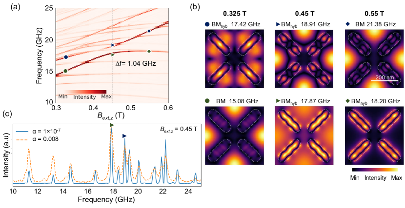
Figure 3(a) shows the zoomed-in view of field-dependent frequency spectra from Fig. 2(b), revealing key for this study details of the SSI-PMA system’s dynamics. Notably, in this frequency range, some higher-order modes from the nanoelements exhibit hybridization with the bulk modes from the PMA matrix (). In particular, it happens between the higher-order , and the fundamental bulk mode of the matrix. The one centered around 18 GHz at 0.45 T is the strongest among the various hybridizations observed, and it maintains a significant anticrossing frequency gap GHz. The fundamental mode with in-phase magnetization oscillation in the whole matrix, and the 2nd order mode quantized along the short axis of the nanoelement, are involved in this process. The evolution of their profiles with increasing the magnetic field is illustrated in Fig. 3(b) (see also the phase distribution in SI Fig. S9). It is clear that during mode hybridization, the collective oscillations involve contributions from the in-plane magnetized SSI elements, the interface between SSI and PMA matrix as well as the PMA bulk region. Fig. 3(c), whthis considered SS remains evident even with a realistic damping value [40], see the spectra in Fig. 3(c), emphasizing the relevance of these findings to practical applications. Additional details regarding the frequency versus field spectra and the corresponding modes are elaborated in Supplementary Information, Sec. VI.
To elucidate the type of interaction responsible for this hybridization, we introduce a small non-magnetic spacer layer (dimension is about 2 discretization cells) between the SSI nanoelements and the PMA matrix. This breaks off the exchange interactions between the nanoelements and the PMA matrix. As shown in SI Sec. III, this results in a weak mode hybridization with a small anticrossing frequency gap, GHz. This indicates that the observed magnon-magnon coupling, similar to Ref. [41], is primarily driven by exchange interactions between the in-plane magnetized nanoelements and the PMA region. This is in contrast to the previous reports [28, 46, 37], where poor dipolar coupling was responsible for the strong magnon-magnon coupling.
Nevertheless, the dipolar interactions also contribute to the mode coupling in the SSI-PMA system. This is indicated by the 0.32 GHz anti-crossing gap when the exchange coupling between the SSI nanoelements and the PMA matrix is broken, but even more meaningful is the influence of the neighbouring nanoelements on the gap width. We analyzed the frequency-field diagram and mode profiles for both a single nanoelement and two dipolar-coupled nanoelements surrounded by PMA matrix in the unit cell, with exchange coupled SSI nanoelements and PMA matrix (detailed results of these analyses are presented in SI, Sec. IV). We found that the considered hybridization occurs even for a single nanoelement in the unit cell but with a small gap GHz. But, when the dipolar coupling between the two nanoelements is present, the gap increases significantly up to GHz (both at a similar frequency range but a higher magnetic field value 0.5 T), and finally to GHz in a full SSI-PMA system. This suggests that while the exchange interactions alone are sufficient to induce coupling between the modes, the addition of dipolar coupling between the nanoelements significantly enhances it, promising tunability of magnon-magnon coupling and collective SW dynamics over large distances.
To estimate a possibility for experimental observation of our findings, we analyze the average FFT spectra for microwave fields oriented along the - and -axes (see SI, Sec. VIII), corresponding to broadband FMR coplanar waveguide and ring geometry setups, respectively [37, 39, 27, 45]. Simulations reveal hybridized modes in both configurations (see Fig. S8). Notably, for the -axis oriented microwave magnetic field, a significantly stronger absorption is expected due to the more effective excitation of the in-plane magnetized nanoelements in the SSI-PMA structure.
III.3 Tunability of the magnon-magnon coupling strength
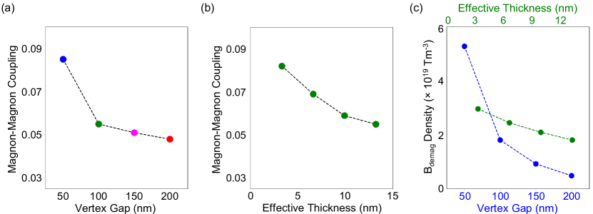
As indicated in the previous section, the coupling between SSI nanoelements enlarges the frequency gap. Thus, the change of the separation between nanoelements shall also significantly influence hybridization between and modes. Figure 4 (a-c) proves this. Supplementary Information, Fig. S4 presents the magnetic field-dependent frequency spectrum for SSI-PMA structures with vertex gaps of 50 nm, 150 nm, and 200 nm, while maintaining the same SSI type (Type 2) throughout the analysis. Hybridization between the 2-order and fundamental is observed across all structures in a similar frequency range, but at different magnetic field values. The anticrossing frequency gap varies with the vertex gap: = 0.84 GHz for the 200 nm gap, = 0.91 GHz for the 150 nm gap, and = 1.63 GHz for the 50 nm gap. These gap values are comparable to existing studies on standard ASIs, i.e., without ferromagnetic matrix, where gaps of around 0.3 GHz [28, 46] and 6.5 GHz [37] have been reported. At smaller vertex gaps, the hybridization between the PMA-SSI boundary region and the bulk of the PMA matrix results in collective oscillations across both areas (Fig. S4(d-f)). However, as the vertex gap increases, these oscillations become predominantly confined to the nanoelements and the adjacent PMA region, with reduced influence of the bulk part of the PMA matrix, and the dipolar coupling between the nanoelements.
A quantitative measure of the magnon-magnon coupling strength is given by the normalized coupling rate, defined as the ratio of the frequency gap to the higher mode frequency, / [37]. Interestingly, decreasing the vertex gap from 200 nm to 50 nm increases the magnon-magnon coupling strength from 0.044 to 0.085 (see, Fig. 4(a)), at a similar frequency range but at shifted magnetic field values at which anticrossing occurs: 0.40 T for a 50 nm vertex gap, 0.46 T for a 150 nm vertex gap, and 0.49 T for a 200 nm vertex gap (Fig. S4(a-c)). This coupling enhancement is primarily attributed to the closer proximity and higher density of nanoelements in the PMA matrix. Thus, the integration of the ferromagnet[47] and the arrangement of a dense array of nanoelements significantly enhances the traditionally weak dipolar interactions, resulting in significant dynamic effects and strong coupling. It is noteworthy that these dynamic effects are correlated with the change of the static magnetization at the edges of the nanoelements. They form an S-shaped configuration at a small vertex gap due to the strong dipolar attraction between them and as the vertex gap increases, this S-shaped curvature of the magnetization diminishes [see the inset in Fig. S4 (a-c) in SI].
To further understand the effect of the dipolar field on the magnon-magnon coupling in the SSI-PMA system, we present the plot of the coupling strength as a function of the film thickness in Fig. 4 (b) with the vertex gap of 100 nm. The applied field versus frequency spectrum and the hybridized modes are shown in the SI, Sec. V. Interestingly, magnon-magnon coupling strength gradually increases from 0.055 to 0.082 with decreasing the thickness values from 13.2 nm to 3.3 nm ( = 1.04, 1.10, 1.24 and 1.36 GHz for the 13.2, 9.9, 6.6, and 3.3 nm thickness values, respectively). This is an unexpected result since increasing the thickness effectively increases the magnetostatic field in the system, and one might also expect an increase in the dipolar interactions. To isolate the effect of dipolar interactions within and between nanoelements, we normalized the magnetostatic field by the volume of the system, thereby removing the dependence on both thickness and vertex gap. In Fig. 4(c), we plot the magnetostatic field density as a function of vertex gap at a fixed thickness of 13.2 nm, and as a function of the film thickness at a vertex gap of 100 nm. These results indicate that decreasing the vertex gap increases the magnetostatic field density due to enhanced dipolar coupling between the nanoelements, which, in turn, leads to a more pronounced dynamic magnon-magnon hybridization. Conversely, reducing only the effective thickness at a constant vertex gap results in an increased internal magnetic field within the nanoelements [48], which is reflected in the increased magnetostatic field density and stronger coupling between the magnons.
III.4 Magnon-magnon hybridization in a ground and monopole vertex configurations
As introduced in Fig. 1, in the SSI-PMA, as well as in classical square lattice ASIs [22, 49, 50], the magnetization configuration at the vertex can also be in Type 1, i.e., the lowest energy state in ASIs, or at high energy states Type 3 or Type 4. These possibilities are promising for the reconfigurability of the system for magnonic applications [26, 39, 38]. In this section, we show how changing the vertex type in the unit cell of SSI-PMA affects the magnon-magnon hybridization found in the system with Type 2 vertices.
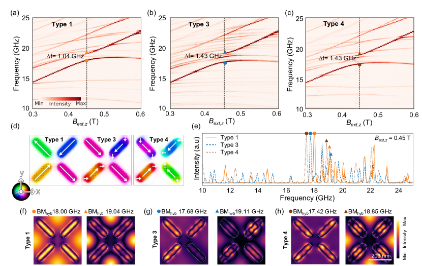
The frequency spectrum versus external field and selected SW mode profiles for SSI-PMA with Type 1, Type 3, and Type 4 magnetization configurations in the unit cell are shown in Fig. 5. In all cases, the vertex gap is 100 nm, and the corresponding spectrum for Type 2 is shown in Fig. 3. The selected magnetization state in nanoelements is artificially introduced into the simulations, after which the system is relaxed, according to the procedure detailed in SI, Sec. I. The spectra for Types 1 and 2 show very similar trends in mode hybridization [Fig. 5(a)], with only a slight shift of the modes to higher frequencies (about 0.13 GHz for the hybridized modes [Fig. 5(f) and [Fig. 3(b)]). The nature of the EM and in the Type 1 configuration [Fig. S7(a) in SI] is the same as observed in the Type 2 configuration (Fig. 2). In contrast, Types 3 (monopole) and 4 (high-energy monopole state) [Fig. 5(b) and (c), respectively] exhibit different spectra and associated SW amplitude distributions, which will be discussed in detail in the following part of the section.
Unlike in Type 1 or Type 2, in Type 3 the static magnetization configurations in nanoelements are significantly modified, forming the S-state in two of the nanoelements, as depicted in Fig. 5(d), pointing at the strong dipolar coupling between the nanoelements. This leads to frequency splitting of the oscillations at the edges and bulk of the individual nanoelements [see the spectra in Fig. S7(b)]. In the Type 4 configuration, the magnetization of all nanoelements follows an S-state with pronounced curvature at the edges, forming a vortex-like state at the vertex [in Fig. 5(d) it is oriented counterclockwise]. This leads to a reduction of the demagnetization field compared to other vertex configurations and splitting of the EM and modes [Fig. S7(c)]. The selected profiles of low-frequency modes, EMs, and at 0.25 T field for Type 1 Type 3, and Type 4 are shown in Fig. S7(d)-(f). In contrast to the system obeying the ice rule, where excitations are typically collective from all nanoelements, monopole-type systems show rather isolated excitations of the nanoelements, as in Type 3. In the Type 4 structure, however, the EMs cover a pair of nanoelements, and the BMs are excited in all four, but in the orthogonal pairs are of different types.
The strong hybridization observed in Types 1 and 2 also exists in the high-energy monopole states. In Type 3 we observe a strong hybridization between second-order and fundamental mode of PMA but in oppositely coupled nanoelements, as shown in Fig. 5(g), maintaining a significant anticrossing frequency gap GHz at 0.45 T. Remarkably, for Type 4, a collective mode hybridization is observed in Fig. 5(h) with the anticrossing frequency gap width similar to Type 3 (see also the phase distribution in SI Fig. S9).
The estimated magnon-magnon coupling strength for Type 1 is 0.055, while for the monopole states, it is 0.075. Previous studies have already shown that SW mode hybridization and an anticrossing gap in ASIs composed of the bilayered nanodots are enhanced, e.g., gap width increases from 0.22 GHz to 0.30 GHz in transitioning from ground to monopole state [39]. Our results indicate that when square ice is embedded in a PMA matrix and both dipolar and exchange interactions play an important role, the monopole state also further enhances the magnon-magnon coupling strength.
It is worth noting that several magnonic modes are present within the anti-crossing frequency gap, which is particularly evident in Type 3. Such multimode coupling is quite common, especially at higher frequencies, in magnetic systems with complex structures and magnetization textures [51]. The strongest modes are assumed to be dominant. We follow the same approach and consider the high amplitude mode to have strong coupling to the fundamental mode of the PMA, while other modes have weaker coupling. Furthermore, these strongest coupled modes should be visible in standard broadband ferromagnetic resonance measurements for both in-plane and out-of-plane microwave magnetic field excitations associated with the microstrip (or coplanar microwave) or ring type of microwave antenna, respectively, as shown in SI Fig. S8.
IV Conclusion
We investigate the SW dynamics and mode hybridization in a square ASI system (SSI) immersed in the ferromagnetic matrix with PMA (SSI-PMA), revealing complex spectral compositions and unique dynamics that are absent in standalone SSI systems. We show that embedding the SSI in the PMA matrix introduces additional SW modes and interactions into the system, leading to hybridization between the bulk modes of the SSI nanoelements and the fundamental bulk modes of the PMA, resulting in substantial anticrossing frequency gaps. In addition to the previously reported dipolar coupling in standard ASIs, we demonstrate that exchange interactions are crucial for facilitating mode hybridization in SSI-PMA system. For the ground state vertex configurations of the magnetization in nanoelements (Types 1 and 2), we observed an anticrossing frequency gap of 1.04 GHz, which points to the magnon-magnon coupling strength of 0.055. This can be adjusted by changing the vertex gap between the nanoelements and also the effective thickness of the structure. Importantly, we show that the strength of this magnon-magnon coupling can also be modulated by reconfiguring the magnetization orientation in SSI nanoelements. In particular, we show that high monopole vertex states (Types 3 and 4) of SSIs exhibit different spectra from low energy states with an enhanced anticrossing frequency gap of 1.43 GHz, giving a coupling strength of 0.075, i.e., 36% enhancement.
Although the proposed structure is based on Co/Pd multilayers with in-plane magnetized nanoelements resulting from the destruction of anisotropy by ion bombardment, the simulations show that, assuming rational, relatively high damping and using standard broadband FMR measurements, the described coupling should be measurable. Further improvement can be achieved by replacing metallic multilayers of PMA with low-damping materials, e.g. dopped YIG [52].
Our results demonstrate that the SSI-PMA system is a new kind of ASI with enhanced dynamical magnetic interactions, promising for magnonic applications and further exploration ASI for SW propagation. Given the importance of recent advances in vertex-state dependent neuromorphic computing capabilities within bi-layered ASI systems [37, 33], our findings offer a promising new approach for realising similar systems without patterning, but with enhanced functionality.
Acknowledgements.
The study has received financial support from the National Science Centre of Poland, Grant Nos. UMO-2020/37/B/ST3/03936 and 2023/49/N/ST3/03538. The simulations were partially performed at the Poznan Supercomputing and Networking Center (Grant No. PL0095-01).V References
References
- [1] M. Krawczyk and D. Grundler, “Review and prospects of magnonic crystals and devices with reprogrammable band structure,” Journal of physics: Condensed matter, vol. 26, no. 12, p. 123202, 2014.
- [2] V. Kruglyak, S. Demokritov, and D. Grundler, “Magnonics,” Journal of Physics D: Applied Physics, vol. 43, no. 26, p. 264001, 2010.
- [3] A. Barman and J. Sinha, Spin dynamics and damping in ferromagnetic thin films and nanostructures, vol. 1. Springer, 2018.
- [4] A. Barman, G. Gubbiotti, S. Ladak, A. O. Adeyeye, M. Krawczyk, J. Gräfe, C. Adelmann, S. Cotofana, A. Naeemi, V. I. Vasyuchka, et al., “The 2021 magnonics roadmap,” Journal of Physics: Condensed Matter, vol. 33, no. 41, p. 413001, 2021.
- [5] A. V. Chumak, P. Kabos, M. Wu, C. Abert, C. Adelmann, A. Adeyeye, J. Åkerman, F. G. Aliev, A. Anane, A. Awad, et al., “Advances in magnetics roadmap on spin-wave computing,” IEEE Transactions on Magnetics, vol. 58, no. 6, pp. 1–72, 2022.
- [6] B. Flebus, D. Grundler, B. Rana, Y. Otani, I. Barsukov, A. Barman, G. Gubbiotti, P. Landeros, J. Akerman, U. S. Ebels, et al., “The 2024 magnonics roadmap,” Journal of Physics: Condensed Matter, vol. 36, p. 363501, 2024.
- [7] A. Haldar, D. Kumar, and A. O. Adeyeye, “A reconfigurable waveguide for energy-efficient transmission and local manipulation of information in a nanomagnetic device,” Nature nanotechnology, vol. 11, no. 5, pp. 437–443, 2016.
- [8] A. Barman, S. Mondal, S. Sahoo, and A. De, “Magnetization dynamics of nanoscale magnetic materials: A perspective,” Journal of Applied Physics, vol. 128, no. 17, 2020.
- [9] D. Grundler, “Reconfigurable magnonics heats up,” Nature Physics, vol. 11, no. 6, pp. 438–441, 2015.
- [10] A. V. Chumak, A. A. Serga, and B. Hillebrands, “Magnon transistor for all-magnon data processing,” Nature communications, vol. 5, no. 1, p. 4700, 2014.
- [11] L. Ji, R. Zhao, X. Hu, C. Hu, X. Shen, X. Liu, X. Zhao, J. Zhang, W. Chen, and X. Zhang, “Reconfigurable ferromagnetic resonances by engineering inhomogeneous magnetic textures in artificial magnonic crystals,” Advanced Functional Materials, vol. 32, no. 20, p. 2112956, 2022.
- [12] K. Szulc, S. Tacchi, A. Hierro-Rodriguez, J. Diaz, P. Gruszecki, P. Graczyk, C. Quiros, D. Marko, J. I. Martin, M. Velez, D. S. Schmool, G. Carlotti, M. Krawczyk, and L. M. Alvarez-Prado, “Reconfigurable magnonic crystals based on imprinted magnetization textures in hard and soft dipolar-coupled bilayers,” ACS Nano, vol. 16, pp. 14168–14177, Sep 2022.
- [13] L. J. Heyderman and R. L. Stamps, “Artificial ferroic systems: novel functionality from structure, interactions and dynamics,” Journal of Physics: Condensed Matter, vol. 25, no. 36, p. 363201, 2013.
- [14] C. Nisoli, R. Moessner, and P. Schiffer, “Colloquium: Artificial spin ice: Designing and imaging magnetic frustration,” Reviews of Modern Physics, vol. 85, no. 4, pp. 1473–1490, 2013.
- [15] S. Lendinez and M. Jungfleisch, “Magnetization dynamics in artificial spin ice,” Journal of Physics: Condensed Matter, vol. 32, no. 1, p. 013001, 2019.
- [16] I. Gilbert, G.-W. Chern, S. Zhang, L. O’Brien, B. Fore, C. Nisoli, and P. Schiffer, “Emergent ice rule and magnetic charge screening from vertex frustration in artificial spin ice,” Nature Physics, vol. 10, no. 9, pp. 670–675, 2014.
- [17] S. Ladak, D. Read, G. Perkins, L. Cohen, and W. Branford, “Direct observation of magnetic monopole defects in an artificial spin-ice system,” Nature Physics, vol. 6, no. 5, pp. 359–363, 2010.
- [18] A. D. King, C. Nisoli, E. D. Dahl, G. Poulin-Lamarre, and A. Lopez-Bezanilla, “Qubit spin ice,” Science, vol. 373, no. 6554, pp. 576–580, 2021.
- [19] W. Branford, S. Ladak, D. E. Read, K. Zeissler, and L. Cohen, “Emerging chirality in artificial spin ice,” Science, vol. 335, no. 6076, pp. 1597–1600, 2012.
- [20] J. Drisko, T. Marsh, and J. Cumings, “Topological frustration of artificial spin ice,” Nature communications, vol. 8, no. 1, p. 14009, 2017.
- [21] A. May, M. Saccone, A. van den Berg, J. Askey, M. Hunt, and S. Ladak, “Magnetic charge propagation upon a 3d artificial spin-ice,” Nature communications, vol. 12, no. 1, p. 3217, 2021.
- [22] S. Gliga, E. Iacocca, and O. G. Heinonen, “Dynamics of reconfigurable artificial spin ice: Toward magnonic functional materials,” APL Materials, vol. 8, no. 4, 2020.
- [23] C. Nisoli, V. Kapaklis, and P. Schiffer, “Deliberate exotic magnetism via frustration and topology,” Nature Physics, vol. 13, no. 3, pp. 200–203, 2017.
- [24] S. H. Skjærvø, C. H. Marrows, R. L. Stamps, and L. J. Heyderman, “Advances in artificial spin ice,” Nature Reviews Physics, vol. 2, no. 1, pp. 13–28, 2020.
- [25] D. Petti, S. Tacchi, and E. Albisetti, “Review on magnonics with engineered spin textures,” Journal of Physics D: Applied Physics, vol. 55, no. 29, p. 293003, 2022.
- [26] S. Gliga, A. Kákay, R. Hertel, and O. G. Heinonen, “Spectral analysis of topological defects in an artificial spin-ice lattice,” Physical review letters, vol. 110, no. 11, p. 117205, 2013.
- [27] M. Jungfleisch, W. Zhang, E. Iacocca, J. Sklenar, J. Ding, W. Jiang, S. Zhang, J. Pearson, V. Novosad, J. Ketterson, et al., “Dynamic response of an artificial square spin ice,” Physical Review B, vol. 93, no. 10, p. 100401, 2016.
- [28] T. Dion, J. Gartside, A. Vanstone, K. Stenning, D. Arroo, H. Kurebayashi, and W. Branford, “Observation and control of collective spin-wave mode hybridization in chevron arrays and in square, staircase, and brickwork artificial spin ices,” Physical Review Research, vol. 4, no. 1, p. 013107, 2022.
- [29] S. Lendinez, M. T. Kaffash, and M. B. Jungfleisch, “Emergent spin dynamics enabled by lattice interactions in a bicomponent artificial spin ice,” Nano Letters, vol. 21, no. 5, pp. 1921–1927, 2021.
- [30] S. Lendinez, M. T. Kaffash, O. G. Heinonen, S. Gliga, E. Iacocca, and M. B. Jungfleisch, “Nonlinear multi-magnon scattering in artificial spin ice,” Nature Communications, vol. 14, no. 1, p. 3419, 2023.
- [31] S. Lendinez, M. Taghipour Kaffash, and M. B. Jungfleisch, “Observation of mode splitting in artificial spin ice: A comparative ferromagnetic resonance and brillouin light scattering study,” Applied Physics Letters, vol. 118, no. 16, 2021.
- [32] S. Gliga, A. Kákay, L. J. Heyderman, R. Hertel, and O. G. Heinonen, “Broken vertex symmetry and finite zero-point entropy in the artificial square ice ground state,” Physical Review B, vol. 92, no. 6, p. 060413, 2015.
- [33] L. Manneschi, I. T. Vidamour, K. D. Stenning, J. C. Gartside, C. Swindells, G. Venkat, D. Griffin, S. Stepney, W. R. Branford, T. Hayward, et al., “Optimising network interactions through device agnostic models,” arXiv preprint arXiv:2401.07387, 2024.
- [34] D. MacNeill, J. T. Hou, D. R. Klein, P. Zhang, P. Jarillo-Herrero, and L. Liu, “Gigahertz frequency antiferromagnetic resonance and strong magnon-magnon coupling in the layered crystal crcl 3,” Physical review letters, vol. 123, no. 4, p. 047204, 2019.
- [35] J. C. Gartside, D. M. Arroo, D. M. Burn, V. L. Bemmer, A. Moskalenko, L. F. Cohen, and W. R. Branford, “Realization of ground state in artificial kagome spin ice via topological defect-driven magnetic writing,” Nature nanotechnology, vol. 13, no. 1, pp. 53–58, 2018.
- [36] P. K. Pal, A. K. Mondal, and A. Barman, “Using magnons as a quantum technology platform: a perspective,” Journal of Physics: Condensed Matter, 2024.
- [37] T. Dion, K. D. Stenning, A. Vanstone, H. H. Holder, R. Sultana, G. Alatteili, V. Martinez, M. T. Kaffash, T. Kimura, R. F. Oulton, et al., “Ultrastrong magnon-magnon coupling and chiral spin-texture control in a dipolar 3d multilayered artificial spin-vortex ice,” Nature Communications, vol. 15, no. 1, p. 4077, 2024.
- [38] A. K. Mondal, A. K. Chaurasiya, K. D. Stenning, A. Vanstone, J. C. Gartside, W. R. Branford, and A. Barman, “Brillouin light scattering spectral fingerprinting of magnetic microstates in artificial spin ice,” Nano Today, vol. 59, p. 102497, 2024.
- [39] J. C. Gartside, A. Vanstone, T. Dion, K. D. Stenning, D. M. Arroo, H. Kurebayashi, and W. R. Branford, “Reconfigurable magnonic mode-hybridisation and spectral control in a bicomponent artificial spin ice,” Nature communications, vol. 12, no. 1, p. 2488, 2021.
- [40] S. Pan, S. Mondal, M. Zelent, R. Szwierz, S. Pal, O. Hellwig, M. Krawczyk, and A. Barman, “Edge localization of spin waves in antidot multilayers with perpendicular magnetic anisotropy,” Physical Review B, vol. 101, no. 1, p. 014403, 2020.
- [41] M. Moalic, M. Zelent, K. Szulc, and M. Krawczyk, “The role of non-uniform magnetization texture for magnon–magnon coupling in an antidot lattice,” Scientific Reports, vol. 14, no. 1, p. 11501, 2024.
- [42] S. Pal, B. Rana, S. Saha, R. Mandal, O. Hellwig, J. Romero-Vivas, S. Mamica, J. Klos, M. Mruczkiewicz, M. Sokolovskyy, et al., “Time-resolved measurement of spin-wave spectra in coo capped [co (t)/pt (7å)] n-1 co (t) multilayer systems,” Journal of Applied Physics, vol. 111, no. 7, 2012.
- [43] A. Vansteenkiste, J. Leliaert, M. Dvornik, M. Helsen, F. Garcia-Sanchez, and B. Van Waeyenberge, “The design and verification of mumax3,” AIP advances, vol. 4, no. 10, 2014.
- [44] M. Moalic and M. Zelent, “Mathieumoalic/amumax: 2023.10.26,” Oct. 2023.
- [45] A. Ghosh, F. Ma, J. Lourembam, X. Jin, R. Maddu, Q. J. Yap, and S. Ter Lim, “Emergent dynamics of artificial spin-ice lattice based on an ultrathin ferromagnet,” Nano Letters, vol. 20, no. 1, pp. 109–115, 2019.
- [46] X. Shen, H. Chen, D. Shi, H. Xia, J. Xu, F. Zeng, and Y. Wu, “Dipolar coupling effect on magnetization dynamics in artificial kagome spin ices,” Physical Review B, vol. 106, no. 14, p. 144413, 2022.
- [47] H. Qin, G.-J. Both, S. J. H am al ainen, L. Yao, and S. van Dijken, “Low-loss yig-based magnonic crystals with large tunable bandgaps,” Nature Communications, vol. 9, p. 5445, Dec 2018.
- [48] Y. Li, G. Gubbiotti, F. Casoli, S. A. Morley, F. J. Goncalves, M. C. Rosamond, E. H. Linfield, C. H. Marrows, S. McVitie, and R. Stamps, “Thickness dependence of spin wave excitations in an artificial square spin ice-like geometry,” Journal of Applied Physics, vol. 121, no. 10, 2017.
- [49] A. Farhan, P. M. Derlet, A. Kleibert, A. Balan, R. V. Chopdekar, M. Wyss, J. Perron, A. Scholl, F. Nolting, and L. J. Heyderman, “Direct observation of thermal relaxation in artificial spin ice,” Physical review letters, vol. 111, no. 5, p. 057204, 2013.
- [50] X. Zhang, Y. Lao, J. Sklenar, N. S. Bingham, J. T. Batley, J. D. Watts, C. Nisoli, C. Leighton, and P. Schiffer, “Understanding thermal annealing of artificial spin ice,” APL Materials, vol. 7, no. 11, 2019.
- [51] A. Ghirri, C. Bonizzoni, M. Maksutoglu, A. Mercurio, O. Di Stefano, S. Savasta, and M. Affronte, “Ultrastrong magnon-photon coupling achieved by magnetic films in contact with superconducting resonators,” Physical Review Applied, vol. 20, no. 2, p. 024039, 2023.
- [52] S. Das, R. Mansell, L. Flajšman, L. Yao, J. W. van der Jagt, S. Chen, D. Ravelosona, L. H. Diez, and S. van Dijken, “Tuning of perpendicular magnetic anisotropy in bi-substituted yttrium iron garnet films by he+ ion irradiation,” arXiv preprint arXiv:2410.04849, 2024.