article \step[fieldset=language, null] \step[fieldset=url, null] \step[fieldset=doi, null] \step[fieldset=issn, null] \step[fieldset=isbn, null] \step[fieldset=note, null] \step[fieldset=editor, null] \step[fieldset=urldate, null] \step[fieldset=file, null] \DeclareSourcemap \maps \map \pertypeinproceedings \step[fieldset=language, null] \step[fieldset=url, null] \step[fieldset=doi, null] \step[fieldset=issn, null] \step[fieldset=isbn, null] \step[fieldset=note, null] \step[fieldset=editor, null] \step[fieldset=urldate, null] \step[fieldset=file, null] \DeclareSourcemap \maps \map \pertypeincollection \step[fieldset=language, null] \step[fieldset=url, null] \step[fieldset=doi, null] \step[fieldset=issn, null] \step[fieldset=isbn, null] \step[fieldset=note, null] \step[fieldset=editor, null] \step[fieldset=urldate, null] \step[fieldset=file, null]
Conjugate momentum based thruster force estimate in dynamic multimodal robot
Abstract
In a multi-modal system which combines thruster and legged locomotion such our state-of-the-art Harpy platform to perform dynamic locomotion. Therefore, it is very important to have a proper estimate of Thruster force. Harpy is a bipedal robot capable of legged-aerial locomotion using its legs and thrusters attached to its main frame. we can characterize thruster force using a thrust stand but it generally does not account for working conditions such as battery voltage. In this study, we present a momentum-based thruster force estimator. One of the key information required to estimate is terrain information. we show estimation results with and without terrain knowledge. In this work, we derive a conjugate momentum thruster force estimator and implement it on a numerical simulator that uses thruster force to perform thruster-assisted walking.
I Introduction
Many schemes exist for estimating external forces. A thorough overview and analysis of them is given in [1]. The most well-established method is the so-called momentum observer [2, 3, 4]. Momentum observer removes the need to estimate the state’s acceleration which is generally noisy in nature. It also removes the need for inversion matrices which can lead to numerical inaccuracy. Due to these advantages, it has been widely used in many applications such as human-robot interaction [5, 6], estimating ground contact force in legged locomotion [7, 8, 9] and estimating the collision force in flying drones [10]. Recent work has explored the application of thruster and posture manipulation in state-of-the-art robots such as the Multi-modal mobility morphobot (M4) [11, 12, 13] and LEONARDO [14, 15, 16, 17, 12, 18, 19].
The M4 robot aims to enhance locomotion versatility by integrating posture control and thrust vectoring, thereby enabling walking, wheeling, flying, and loco-manipulation. Similarly, LEONARDO, a bipedal quadcopter, is capable of both quasi-static walking and flying. However, neither robot fully achieves dynamic legged locomotion and aerial mobility. The integration of these modes presents a significant challenge due to their conflicting requirements (see [11]).
To execute dynamic maneuvers, it is crucial to have an accurate estimate of the thruster force. While thruster stands can be used to characterize the generated thruster force under ideal conditions, it is challenging to account for test conditions such as battery voltage drop. Therefore, onboard thruster force estimation is essential and can be utilized by controllers such as Model Predictive Control (MPC) and Quadratic Programming (QP).
A commonly used method for estimating thruster forces in aerial manipulators involves focusing solely on the dynamics of the flying platform and treating the forces exerted by the manipulator arm as external disturbances. This approach enables the use of single-body estimation techniques to estimate thrust forces [20]. However, this method is not suitable for thruster-assisted bipedal robots because the dynamics of the flying and manipulator components are coupled. Another method proposed for thrust estimation framework for the multi-link robot iRonCub [21], a multibody robot with jet propulsion attached to its back and hands, proposes an Extended Kalman Filter (EKF) based on centroidal momentum and propeller models. This framework cannot be directly implemented as their robot is in a flying state, and during contact ground reaction forces are given force sensor.
This work proposes the use of the Momentum Observer methodology to estimate the thruster force in our multimodal platform, Harpy. By implementing this approach, we aim to achieve more precise control and enhance the overall performance of the robot in dynamic environments.
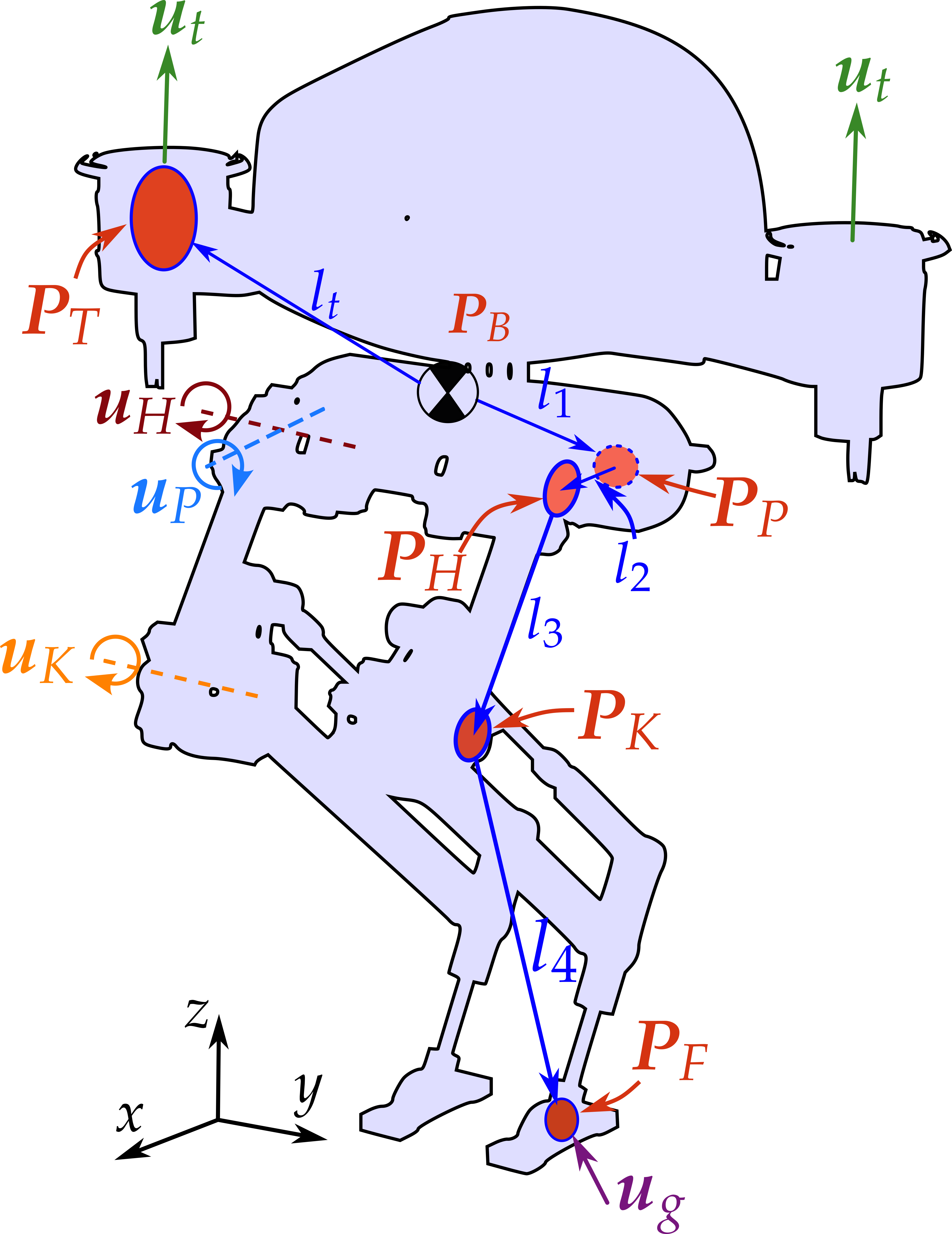
In this study, we employ a detailed model of Harpy (depicted in Fig. 1) using Matlab to evaluate our estimator’s effectiveness. Harpy is equipped with eight custom-designed high-energy density actuators for dynamic walking, along with electric ducted fans mounted on its torso sides. Harpy’s height measures 600 cm and weighs 4 Kg. It hosts a computer based on Elmo amplifiers for real-time low-level control command executions.
Harpy’s design integrates advantages from both aerial and dynamic bipedal legged systems. Currently, the hardware design and assembly of Harpy have been completed [22], and our primary goal is to explore various control design strategies for this platform [19, 23, 24].
In this work, we aim to design a conjugate momentum-based estimator to estimate thruster forces. The main contributions of this paper are: a) Formulation of Conjugate momentum-based observer for thruster forces. b) Comparison of estimate with and without knowing the terrain information.
This work is structured as follows: we present brief over view of modeling where it show dynamic model, complaint ground model and reduced-order model. Next, we present a conjugate momentum observer followed by results and conclusion.
II Dynamic modeling and control
This section contains a brief overview of the dynamic model used in this paper for simulation, which is followed by a reduced-order model (ROM) and controller design.
Figure 1 illustrates the degrees of freedom (DoF) of the robot’s leg, which includes three actuated joints: hip frontal (Pelvis ), hip sagittal ( hip ), and knee sagittal (knee ) joints. Combined with the robot’s body, the system has a total of 12 DoF.
The thrusters are designed to rotate about the body’s sagittal axis. However, for simplification, we assume that the thrusters can provide forces in any direction, and the thruster dynamics are ignored. The model is further simplified by assuming that the mass is concentrated at the body and the joint motors, resulting in a simpler model where the lower leg (shin and foot) is massless. The foot is considered small and modeled as a point foot, simplifying the ground force effect on the system at the cost of reduced stability due to the smaller support polygon.
The dynamic model of Harpy, used in the numerical simulation, is derived using the Euler-Lagrangian dynamic formulation. The body rotation is derived using the modified Lagrangian for dynamics in SO(3) to avoid gimbal lock or singularity present in the Tait-Bryan representation of the rotation matrix. Let be the system states, defined as follows:
| (1) |
where represents the dynamical system states other than . represents the hip frontal and hip sagittal joint angle in the order . The knee sagittal angle , which is not associated with any mass, is updated using the knee joint acceleration input . Then, the system acceleration can be derived as follows:
| (2) |
here is the joint actuation input, is the thruster forces and is the GRF. each of these input are separated into the left and right components. Mapping matrix for joint is . and are used to map the thruster and GRF to generalized coordinates, respectively. and is modelled in the further section
| (3) |
II-A Compliant Ground Model
For simulation, GRF is modeled using the compliant ground model with undamped rebound, while friction is modeled using the Stribeck friction model, defined as follows:
| (4) | ||||
where inertial foot position is defined by and . Spring and damping stiffness for the ground is denoted by and . , , and are the Coulomb, static, and viscous friction coefficients, respectively, and is the Stribeck velocity. is set to if for the undamped rebound model, and friction in the direction follows a similar derivation to . Then, the ground force model is defined as follows:
| (5) |
where denotes the Heaviside function, while and represent the left and right ground forces, which are formed using their respective components , , and .
II-B Reduced-Order model
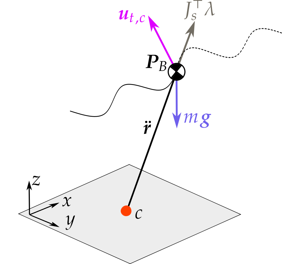
The thruster controller was developed using the VLIP model. In this model, the center of pressure (CoP), represented as , is calculated as the weighted average position of the feet: , where for . In the Harpy full-dynamics model, which employs a point foot, corresponds to the stance foot position during the single support (SS) phase. The VLIP model is underactuated without thrusters, but adding thrusters makes the system fully actuated, allowing for trajectory tracking. Consequently, the VLIP model is derived as follows:
| (6) |
where represents the mass of the VLIP model, which in this case is the total mass of the system, and denotes the thruster forces about the CoM. The constraint force is established to maintain the leg length equal to the leg conformation, utilizing the following constraint equation:
| (7) |
which is designed to maintain the leg length’s second derivative equal to . This constraint force also constitutes the GRF as long as the friction cone constraint is satisfied. Assuming no slip (), the inputs to the system are , which controls the body position about the vector by adjusting the leg length, and the thrusters , which control the remaining degrees of freedom.
II-C Controller design
The joint controller is designed to follow the desired foot positions by employing inverse kinematics to determine the target joint angles. Let represent the joint angles of the legs. Given the trajectory , the joint controller can be derived using a simple PID controller. The trajectory to be tracked is developed through optimization on a D version of the dynamic model shown in 2. However, this trajectory is unstable when applied to the full 3D system, necessitating the use of thrusters to stabilize the dynamics. The controller uses thruster force to stabilize the roll and yaw motion of the robot according to the following law:
| (8) |
Here and are the left and the right thruster force, respectively. and are simply PD controllers to track zero roll and yaw reference angles. Combined thrust forces are formed by combining in (6) and (8)
| (9) |
III Conjugate momentum observer design
The approach of estimation using generalized momentum was presented in [1], [25], and [2], driven by the aim to avoid inversion of the inertia matrix and estimation of states acceleration.n We use this approach to estimate the thruster force . Consider observer dynamics as,
| (10) |
where, is function which depends on full system states. is the sysmetric, positive definite matrix. represents Christoffel symbols and is the gravity vector. represents ground reaction force. The generalized momentum of robot is
By differentiating the generalized momentum we get
| (11) |
In this context, represents the estimated thruster force. The term is defined as , where is derived from the Lagrangian dynamics, and is numerically computed as . Under ideal conditions, we assume and . Consequently, the dynamic relationship between the estimated generalized thruster force and the actual generalized thruster force is defined as
| (13) | ||||
Equation (13) shows that is low pass filter of thruster force. [1], shows that as . We can obtain the estimated GRF by integrating equation (13)
| (14) |
Further, it is possible to estimate the body frame thruster force by using jacobian .
| (15) |
From equation (14), it is evident that the estimation of thruster force necessitates the knowledge of ground reaction forces. There are two primary methodologies for estimating ground reaction forces: employing force sensors attached to the foot, or utilizing a contact constraint model. In the subsequent section, we will employ the contact constraint
III-A Contact constraint model
To estimate the ground reaction force, we constraint the stance foot acceleration to zero and we get . By using this constraint and robot’s dynamical acceleration (2), we get
| (16) |
where is the Moore-Penrose pseudo-inverse and is the matrix of stacked foot contact Jacobians. During the double support phase, is not full rank and this makes the estimation of the ground forces inherently inaccurate.
IV Results
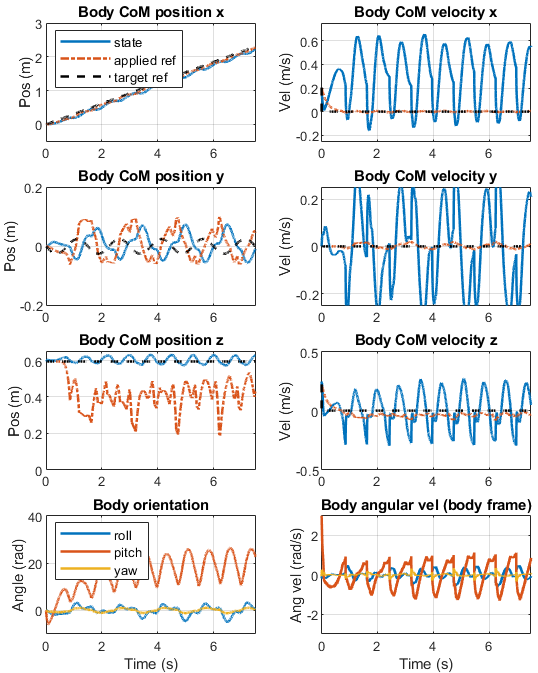
The numerical simulation and Observer design are done in the Matlab. We used RK4 scheme to propogate the model forward. Fig. 8 shows the position, velocity and orientation of the robot while performing thruster assisted walking.
IV-A Simulation Specifications
In this section, all units are in N, kg, m, s. The left leg of robot as following dimensions: , , and . The right side has the axis component inverted. The following mass and inertias were used for simulation: , , and . Finally, ground parameters were , , , and .
IV-B Results and Discussion
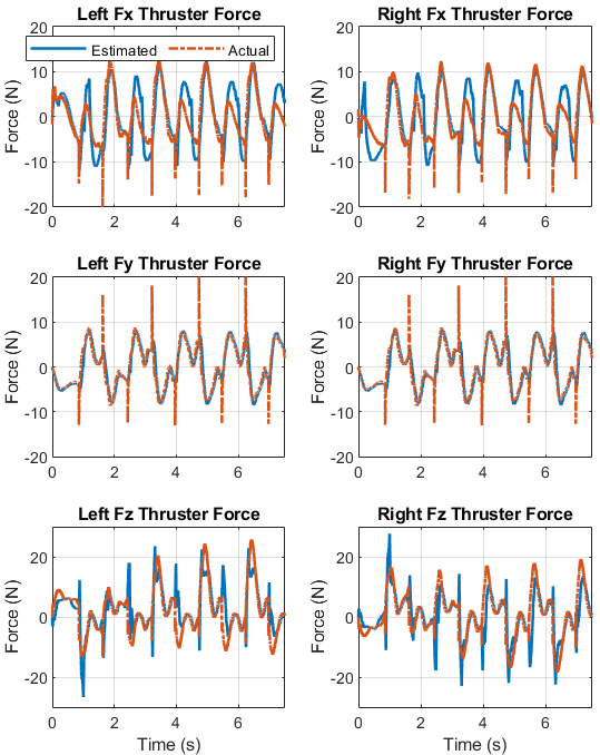
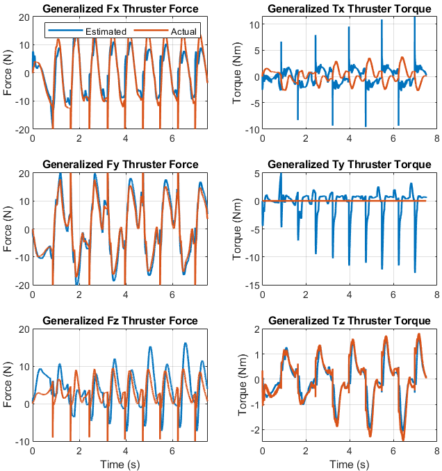
As discussed previously, To estimate the thruster force, we need to have information about the ground terrain.First method is to install force sensor on the foot which essentially allows to measure directly. Fig. 6 shows estimation of thruster force by inputing the ground reaction force from complaint ground model (4). Observer gain used for estimation were . Generalized force and torque fairly matches apart from generalized torque in direction which is due to filter lag. Second method is to use constraint model. By using (15), we found the body frame thruster force shown in fig. 7.
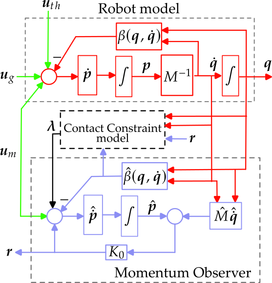
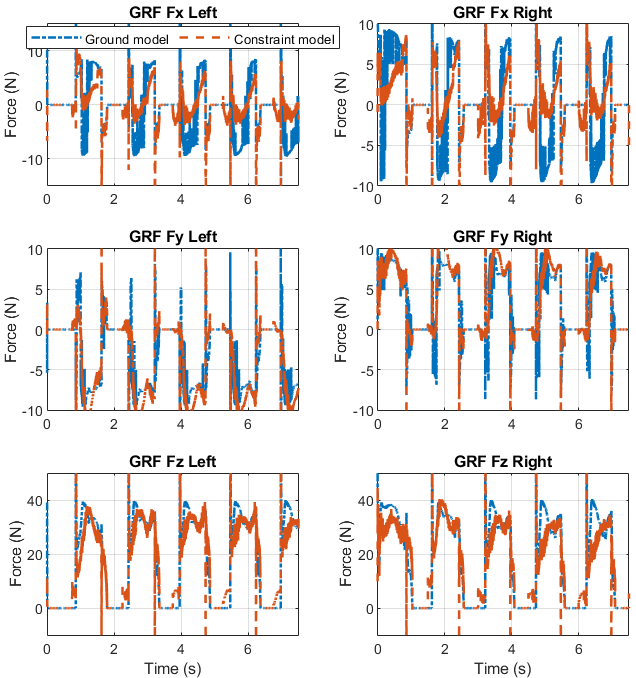
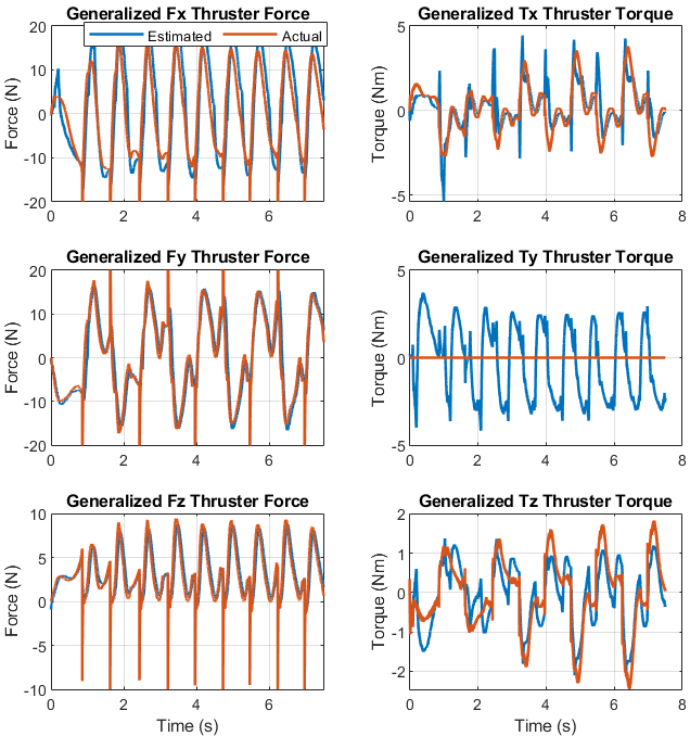
Fig. 3 show the flow chart for estimator dynamics when constraint model is used. The algorithm indicates that the constraint model relies on the estimated thruster force and the observer dynamics terms . Consequently, any error in these estimations will result in a greater error in the ground reaction force estimation. To mitigate this, we can increase the observer gain. Fig. 5 show the generalized thruster force estimation using constraint model (16) and Observer gain were set as . Generalized force in , and matches fairly well, while in it oscillates about the actual. Generalized Torque and matches with closely with actual torque. Finally fig. 6 shows the comparison between estimated GRF from constrained model with estimated thruster force as input.
To evaluate the performance of our model, we calculated the Root Mean Square Error (RMSE) and subsequently normalized it to facilitate comparison across different datasets and scales. This normalization process yields a value between 0 and 1, where values closer to 0 indicate a better fit of the model to the data. By normalizing the RMSE, we ensure that the error metric is dimensionless and comparable across various contexts, providing a more robust assessment of model performance. Table I shows NRMSE for generalized forces and torque. This is for case where we use conjugate momentum with constraint model. The values are closer to zeros which shows the effectiveness of the method. The largest NRMSE is for which is due to use of constraint model.
| Data | Normalized RMSE |
|---|---|
| 0.115586 | |
| 0.049212 | |
| 0.194566 | |
| 0.110182 | |
| 0.134201 | |
| 0.123929 |
V conclusion
In this work, we presented a conjugate momentum-based observer design for estimating thruster forces. Both the observer and simulation were running on a Matlab numerical simulator. We showed stable thruster-assisted walking simulation. While the robot is performing thruster-assisted walking, the observer is able to accurately tracked the thruster force. Since it is a low pass filter, the accuracy of the estimator highly depends on the ground reaction force information. The observer can accurately track the thruster forces given complete knowledge of ground forces. Alternative, we can also estimate the ground reaction force by using contact constraint. But, in doing so the accuracy of the estimator decreases. Our results demonstrated that the NRMSE values were consistently low, indicating a high degree of accuracy and reliability in our model’s predictions. This normalization process not only facilitated a more comprehensive evaluation but also highlighted the model’s effectiveness in various contexts In future work, we will improve the accuracy of the estimator by introducing a second-order filter. Further, we will use these estimated thruster forces to perform dynamic maneuvers.
References
- [1] Sami Haddadin, Alessandro De Luca and Alin Albu-Schäffer “Robot Collisions: A Survey on Detection, Isolation, and Identification” In IEEE Transactions on Robotics 33.6, 2017, pp. 1292–1312
- [2] A. Luca and R. Mattone “Sensorless Robot Collision Detection and Hybrid Force/Motion Control” In Proceedings of the 2005 IEEE International Conference on Robotics and Automation, 2005, pp. 999–1004
- [3] A. De Luca and R. Mattone “Actuator failure detection and isolation using generalized momenta” In 2003 IEEE International Conference on Robotics and Automation (Cat. No.03CH37422) 1, 2003, pp. 634–639 vol.1
- [4] Peiyuan Cai, Danfu Liu and Lijun Zhu “Predefined-Time External Force Estimation for Legged Robots” In Intelligent Robotics and Applications Singapore: Springer Nature, 2023, pp. 542–552
- [5] Gianluca Garofalo, Nico Mansfeld, Julius Jankowski and Christian Ott “Sliding Mode Momentum Observers for Estimation of External Torques and Joint Acceleration” In 2019 International Conference on Robotics and Automation (ICRA), 2019, pp. 6117–6123
- [6] “On making robots understand safety: Embedding injury knowledge into control - Sami Haddadin, Simon Haddadin, Augusto Khoury, Tim Rokahr, Sven Parusel, Rainer Burgkart, Antonio Bicchi, Alin Albu-Schäffer, 2012” URL: https://journals.sagepub.com/doi/abs/10.1177/0278364912462256?casa_token=zT9wDmGIPrMAAAAA:gr3D3cWNbt9AaTxY3OviIWYYZ94EguNmL_z5KOrOvcj08bazl1xbWYyj9PMjj9wGENT6nr71fLY
- [7] Shaoxun Liu et al. “Sensorless Ground Reaction Force Observation With Disturbance Compensation in Heavy-Legged Robots” In IEEE/ASME Transactions on Mechatronics, 2024, pp. 1–12
- [8] Gerardo Bledt, Patrick M. Wensing, Sam Ingersoll and Sangbae Kim “Contact Model Fusion for Event-Based Locomotion in Unstructured Terrains” In 2018 IEEE International Conference on Robotics and Automation (ICRA), 2018, pp. 4399–4406
- [9] “Residual-based contacts estimation for humanoid robots — IEEE Conference Publication — IEEE Xplore” URL: https://ieeexplore.ieee.org/abstract/document/7803308?casa_token=2RhORD0rn4IAAAAA:3fe9evpFqIEVpAHm23ly55x8MvR9ff_HwCPHTNpoT10zm5e7xUHYW38kAIiSKG5qSoe9kIbr
- [10] Teodor Tomić, Christian Ott and Sami Haddadin “External Wrench Estimation, Collision Detection, and Reflex Reaction for Flying Robots” In IEEE Transactions on Robotics 33.6, 2017, pp. 1467–1482
- [11] Eric Sihite et al. “Multi-Modal Mobility Morphobot (M4) with appendage repurposing for locomotion plasticity enhancement” In Nature Communications 14.1, 2023, pp. 3323
- [12] Eric Sihite et al. “Efficient Path Planning and Tracking for Multi-Modal Legged-Aerial Locomotion Using Integrated Probabilistic Road Maps (PRM) and Reference Governors (RG)” In 2022 IEEE 61st Conference on Decision and Control (CDC), 2022, pp. 764–770
- [13] Ioannis Mandralis, Eric Sihite, Alireza Ramezani and Morteza Gharib “Minimum Time Trajectory Generation for Bounding Flight: Combining Posture Control and Thrust Vectoring” In 2023 European Control Conference (ECC), 2023, pp. 1–7
- [14] Kyunam Kim et al. “A bipedal walking robot that can fly, slackline, and skateboard” In Science Robotics 6.59, 2021, pp. eabf8136
- [15] Pravin Dangol, Eric Sihite and Alireza Ramezani “Control of Thruster-Assisted, Bipedal Legged Locomotion of the Harpy Robot” In Frontiers in Robotics and AI 8, 2021
- [16] Kaier Liang et al. “Rough-Terrain Locomotion and Unilateral Contact Force Regulations With a Multi-Modal Legged Robot” In 2021 American Control Conference (ACC), 2021, pp. 1762–1769
- [17] Eric Sihite, Pravin Dangol and Alireza Ramezani “Optimization-free Ground Contact Force Constraint Satisfaction in Quadrupedal Locomotion” In 2021 60th IEEE Conference on Decision and Control (CDC), 2021, pp. 713–719
- [18] Alireza Ramezani et al. “Generative Design of NU’s Husky Carbon, A Morpho-Functional, Legged Robot” In 2021 IEEE International Conference on Robotics and Automation (ICRA), 2021, pp. 4040–4046
- [19] Pravin Dangol and Alireza Ramezani “Feedback design for Harpy: a test bed to inspect thruster-assisted legged locomotion” In Unmanned Systems Technology XXII 11425 SPIE, 2020, pp. 49–55
- [20] F. Ruggiero et al. “A multilayer control for multirotor UAVs equipped with a servo robot arm” In 2015 IEEE International Conference on Robotics and Automation (ICRA), 2015, pp. 4014–4020
- [21] Hosameldin Awadalla Omer Mohamed et al. “Momentum-Based Extended Kalman Filter for Thrust Estimation on Flying Multibody Robots” In IEEE Robotics and Automation Letters 7.1, 2022, pp. 526–533
- [22] Shreyansh Pitroda “Dynamic multimodal locomotion: a quick overview of hardware and control.”, 2023
- [23] Pravin Dangol, Eric Sihite and Alireza Ramezani “Control of Thruster-Assisted, Bipedal Legged Locomotion of the Harpy Robot” In Frontiers in Robotics and AI 8, 2021
- [24] Shreyansh Pitroda et al. “Capture Point Control in Thruster-Assisted Bipedal Locomotion” In 2024 IEEE International Conference on Advanced Intelligent Mechatronics (AIM), 2024, pp. 1139–1144
- [25] Alessandro De Luca, Alin Albu-Schaffer, Sami Haddadin and Gerd Hirzinger “Collision Detection and Safe Reaction with the DLR-III Lightweight Manipulator Arm” In 2006 IEEE/RSJ International Conference on Intelligent Robots and Systems, 2006, pp. 1623–1630