Joint-repositionable Inner-wireless Planar Snake Robot
Abstract
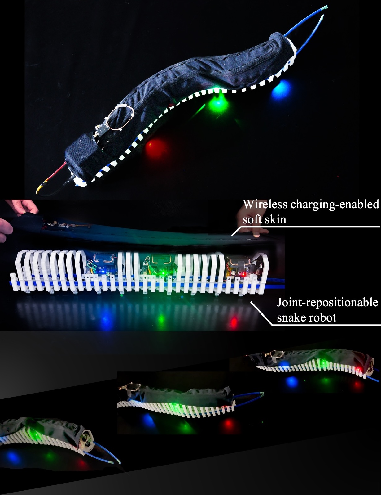
Bio-inspired multi-joint snake robots offer the advantages of terrain adaptability due to their limbless structure and high flexibility. However, a series of dozens of motor units in typical multiple-joint snake robots results in a heavy body structure and hundreds of watts of high power consumption. This paper presents a joint-repositionable, inner-wireless snake robot that enables multi-joint-like locomotion using a low-powered underactuated mechanism. The snake robot, consisting of a series of flexible passive links, can dynamically change its joint coupling configuration by repositioning motor-driven joint units along rack gears inside the robot. Additionally, a soft robot skin wirelessly powers the internal joint units, avoiding the risk of wire tangling and disconnection caused by the movable joint units. The combination of the joint-repositionable mechanism and the wireless-charging-enabled soft skin achieves a high degree of bending, along with a lightweight structure of 1.3 kg and energy-efficient wireless power transmission of 7.6 watts.
I INTRODUCTION
Biological snakes obtain superb locomotion capabilities in rough terrains by adaptively bending their flexible bodies with a high degree of freedom [1, 2]. Multi-joint snake robots inspired by snakes in nature have demonstrated wider terrain adaptability in constrained, unstructured environments over wheeled or legged robots [3]. Despite their adaptive robotic locomotion, efficient and continuous locomotion with the snake robot remains a challenge. The multi-joint mechanical design based on a series of dozens of motor-driven joints results in a heavy structure and hundreds of watts of power consumption due to the challenges associated with motor miniaturization [4, 5]. In the development of lightweight, energy-efficient snake robots, previous work has focused mainly on underactuated joint systems such as wire-driven joint bending or pneumatic soft actuation of the joints [6, 7, 8]. However, the design constraints of wires and pneumatic chambers restrict the variety of robot postures compared to those of multi-joint systems.
To fill this gap, this article presents a new class of underactuated snake robots—joint-repositionable inner-wireless snake robot—. Unlike the typical fixed joint coupling structure composed of numerous motor units and rigid links, we introduce a joint-repositionable design, which dynamically changes the joint coupling configuration by moving at least two joint units along internal flexible rack gears. Our mathematical model and experiments with the physical snake robot demonstrate that the joint-repositionable mechanism realizes two types of basic snake-like locomotion similar to those of conventional multi-joint snake robots. Additionally, a soft robot skin including a wireless charging-enabled coil is mounted on the top side of the robot to prevent the internal power cable from tangling with the moving joint units. The optimized coil design experimentally demonstrates watt-class wireless power transmission with over 50% efficiency while avoiding electromagnetic interference with the metallic motors in the joints. Overall, the joint-repositionable mechanism, powered wirelessly by the soft robot skin, enables basic snake-like movements similar to conventional multi-joint snake robots while maintaining a lightweight design of and efficient energy use through wireless charging (see Figure 1).
II Robot Design and Implementation
II-A Joint-repositionable Mechanism
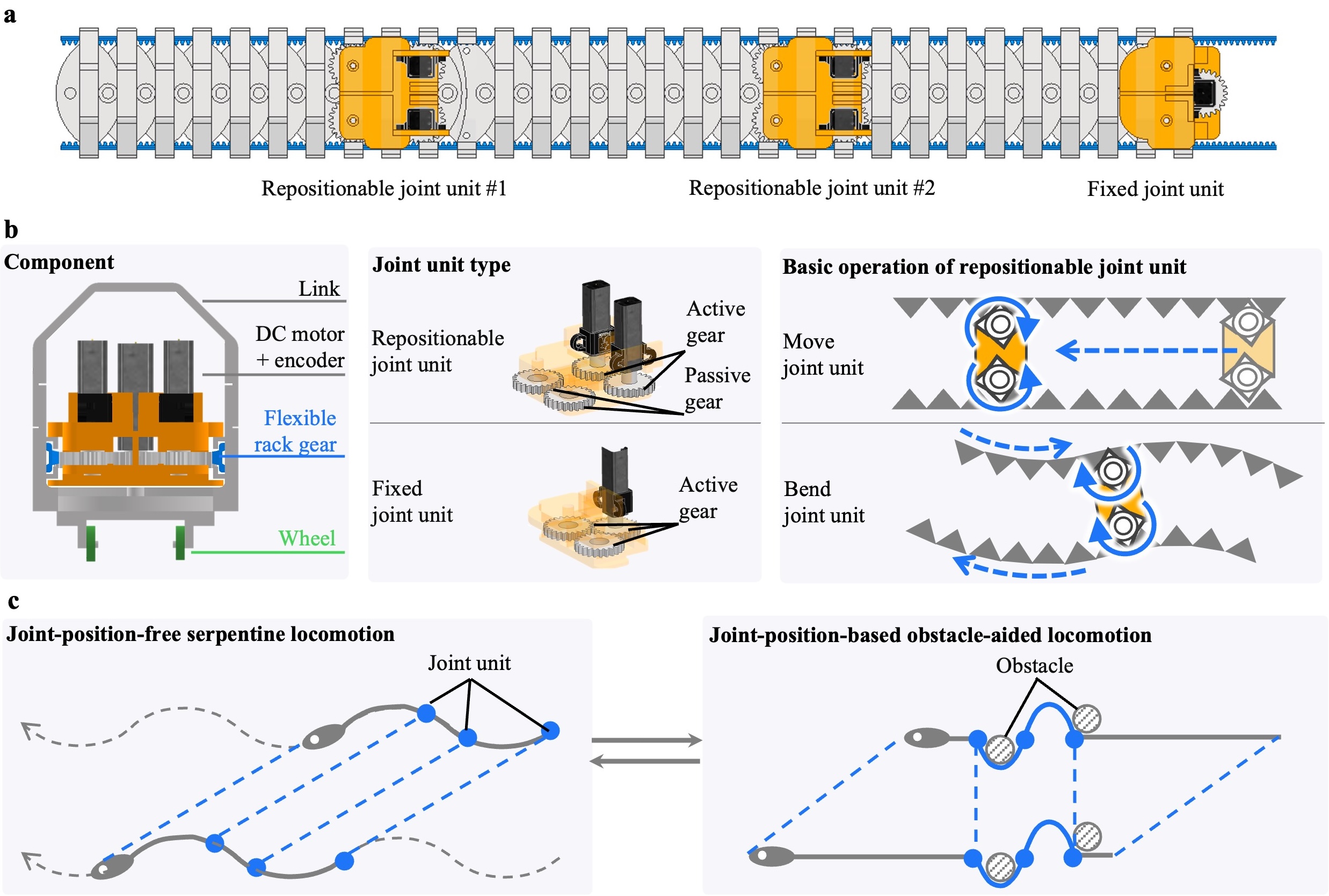
The joint-repositionable mechanism consists of an exoskeleton body with serially connected links, two flexible rack gears passing through the links, and motor-driven joint units that travel along the body (see Figure 2a for the case of ). The links are connected by revolute joints, with some links having passive wheels mounted at the bottom to provide frictional anisotropy. The two rack gears pass through grooves in each link, while their front ends are fixed to the first link and their rear ends are left free. Among joint units, are movable joint units and one is a fixed joint unit. The movable joint unit consists of two motors that move along the robot body, while the fixed joint unit consists of one motor fastened at the rear end of the robot.
The mechanical design and basic operation of the two types of joint units are illustrated in Figure 2b. The two motors in the repositionable joint unit primarily control the robot’s locomotion. When the motors rotate in the same direction, one rack gear moves forward while the other moves backward, creating an S-shaped bend. In contrast, the rotation in opposite directions allows the movable unit to move back and forth along the rack gears. Two active gears connected to the motors transfer the rotation force of the motor to the rack gears, while passive gears are used for hooking the movable units. The fixed joint unit, which only supports bending, uses a single motor to synchronously rotate the two flexible racks.
Based on its basic operation, our robot provides two types of locomotion (see Figure 2c). The first approach is a joint-position-free serpentine locomotion, smoothly navigating in obstacle-free narrow terrains. This locomotion eliminates the need for precise joint positioning, thereby reducing operational time. The second approach is a joint-position-based obstacle-aided locomotion, slowly crawling over surrounding obstacles in the terrain. Adaptive joint positioning is necessary to fit the robot’s shape to C-shaped obstacles. The detail control strategy is described in § III. In total, the joint-repositionable design enables snake-like locomotion while drastically reducing the number of necessary motors.
II-B Wireless Charging-enabled Robot Skin
To realize a joint-repositionable structure, the movable joint units must be lightweight, compact, and freely movable. While equipping small batteries in the joint units allows for untethered and fast movement, it reduces operation time. Conversely, using power supply cables, which connect the joint units to an external power source, can lead to wire tangling or breakage due to joint movement. To overcome this challenge, we employ a wireless power transmission approach for continuous and untethered operation of the movable joint units. Specifically, coil-based inductive charging can efficiently transmit -class power, compared to other wireless charging approach based on electromagnetic waves and capacitive coupling [9, 10, 11]. By inductively transmitting power from the external power module (i.e., robot skin) to the joint units, the joint units equipped with a small battery are able to operate continuously without being limited by battery capacity.
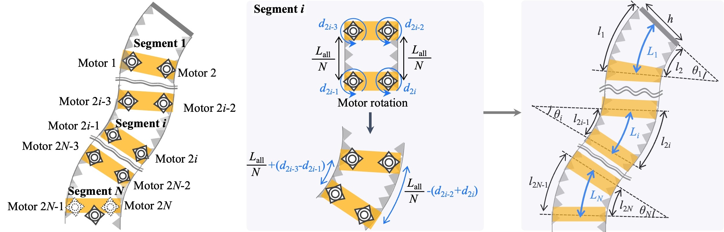
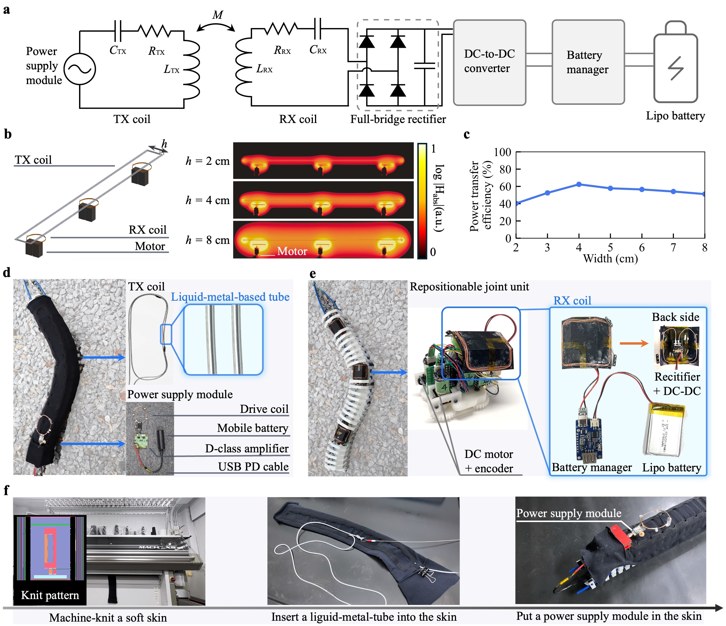
Figure 3a shows the circuit design of the wireless charging-enabled soft robot skin. The skin consists of a transmitter (TX) helical coil connected to a power supply module and three receiver (RX) spiral coils, earch connected to one of the three joint units. Through the inductive coupling between the TX/RX coils, the TX coil wirelessly transmits AC power to the RX coil, which converts the received AC power into DC power via a full-bridge rectifier and then stores the energy in a battery using a DC-DC converter and a battery manager.
Optimizing the size of the helical coil is crucial because the metallic motors inside the snake robot can potentially interact with the inductive field. The wireless power delivery distance from the helical coil is primarily influenced by its shorter side length (i.e., width). To understand the relationship between coil width and maximum power transfer efficiency [12], we conducted an electromagnetic simulator (FEKO, HyperWorks). The simulation model includes i) a helical TX coil with a length of , turns, and a conductivity of , ii) a \qtyproduct4x4 -turn RX coil, and iii) cube-shaped simplified stainless steel motor units. The distances between the TX/RX coils and the RX coil/the motor are and , respectively, and the width of the TX coil varies from to in increments of (see Figure 3b). The results indicate that a wider coil interacts with the motors, while a narrower coil fails to deliver a strong inductive field to the RX coil (see Figure 3c). Consequently, width is chosen for efficient power transmission.
II-C Prototype Implementation
Figure 3de illustrates the prototype of the wireless charging-enabled soft skin, which consists of the liquid-metal-based textile TX coil and the joint-repositionable mechanism, including the RX coil. The joint-repositionable mechanism with a total length of includes 3D-printed passive links with passive wheels, two flexible rack gears, and three joint units. The joint unit has DC motors (1000:1 Motor, Pololu) connected to a magnetic encoder (3499, Pololu). The encoder measures the moving length of the flexible rack driven by the motor. The TX coil uses a liquid-metal-based stretchable tube within a textile designed for elasticity, fabricated by machine knitting (MACH2XS 15S, Shima Seiki) similar to [13, 14] (see Figure 3f). Galinstan (Ga68.5In21.5Sn10, Sichuan HPM) is selected as the liquid metal for its low melting point (), high electrical conductivity (), and low toxicity [15]. The Galinstan was contained in a silicone tube with the inner/outer diameter of /. The power supply module consists of D-class amplifier (EPC9065), DC mobile battery ( Anker Nano Power Bank), and a USB PD cable with output. By contrast, the \qtyproduct4x4 RX coil consists of a -turn copper wire with the diameter of , a full-bridge rectifier (PMEG6010), a DC-to-DC rectifier (MIC29150-5.0), and a battery manager (Lipo Rider Plus). The resonant frequency of the TX/RX coils was tuned at with the distributed chip capacitors () [16, 17]. The inductance (), resistance (), and -factor () of the TX/RX coils at are /, /, and /, respectively. The total weight and average power consumption are (including the skin with the battery: ) and , respectively. The soft skin with DC input sends () DC power to each joint unit wirelessly.
III Modeling and Control
III-A Variable-length Arc-shaped Joint Model
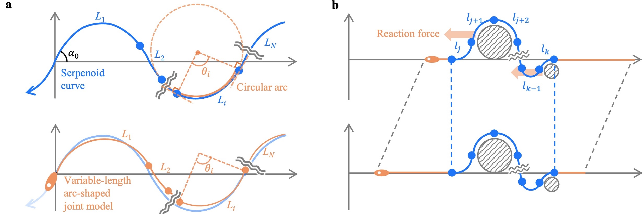
This section describes the generalized kinematic model of our snake robot referred to as the variable-length arc-shaped joint model. Our joint-repositionable snake robot is modeled as a series of multiple arcs with variable lengths. Here, we estimate both the position and angle of the repositionable joints based on the motor rotations in the joint units. First, we assume the joint model with repositionable joint units and fixed joint unit can be divided into arc segments. Note that the first segment is separated by only the -st joint unit. Based on the piecewise constant curvature assumption, each segment is simplified as a circular arc with constant curvatures, enabling simple mathematical modeling of the robot’s shape. Specifically, the -th arc segment () between ()-th and -th joint units can be modeled by three lengths (centerline: , left side line: , right side line: and the arc angle (see Figure 4). The -th repositionable joint unit has two ()-th and -th motors. For simplicity, the -th fixed joint unit is assumed to be composed of the ()-th and -th motors synchronouslly rotating in the reverse direction against the actual motor. With this setup, , , , and can be expressed as follows with a robot width :
| (1) |
where , the total length of the robot centerline, is constant.
Next, we model the change in caused by the motors in the -th segment. We assume that the initial robot shape is straight and that the motor units are evenly positioned. With this initial configuration, each rack gear length is assumed to be . The rotations of the ()-th and -th motors in the -th segment increase and by a length of and , respectively. Since the and -th motors also change the length of the ()-th segment, and can be expressed as follows in terms of , , and .
| (2) |
where and . Note that the counterclockwise rotation of the motor is defined as a positive . Therefore, the conversion of into and can be expressed as follows with Equation 1 and Equation 2:
| (3) |
Equation 3 can be converted as follows:
| (4) |
Equation 4 shows the conversion of the robot configuration ( and ) into motor actuation parameters ().
III-B Joint-position-free Serpentine Locomotion
Among various terrestrial locomotion modes in snakes [4], planar snake robots mainly use serpentine movement and obstacle-aided locomotion (see Figure 5). The serpentine movement enables snake robots to move smoothly in narrow terrains by bending their entire bodies along sinuous curves such as a serpenoid curve [18]. By contrast, obstacle-aided locomotion allows the snake robots to push against terrain irregularities and narrow passage walls [19]. Unlike well-established fixed-length arc-shaped joint models [20, 21, 22], no control method has yet been developed for a variable-length arc-shaped joint model.
First, we discuss how to approximate the serpentine movement by the variable-length arc-shaped joint model, as explained in § III-A. The serpentine movement basically follows a serpentine curve, whose curvature varies sinusoidally. The can be expressed as follows:
| (5) |
where is the time, is the angular frequency, is the distance along the curve, is the length of one-quarter of the curve, and is the winding angle along the curve. Note that represents . Since the serpenoid curve can be approximated by serial segments of circular arcs [21], we approximate the serpenoid curve by our variable-length arc-shaped joint model as follows: First, the serpenoid curve is divided into arc segments with length of -th segment. Then, the arc angle can be calculated as follows with and Equation 5:
| (6) |
where . Lastly, based on Equation 4, we calculate for and from the arc segment to fit the arc segments into the target serpenoid curve. arc segmentation of the serpenoid curve is flexible, thereby allowing the proposed snake robot to perform serpentine locomotion with joint-position-free various segmentation. Note that excessively long segmented arcs causes significant fitting errors.
III-C Joint-position-based Obstacle-aided Locomotion
Obstacle-aided locomotion has been widely studied for snake robots designed to navigate unstructured environments [19, 23, 24]. To enable this form of locomotion with repositionable-joint units, our strategy is to fix the shape of certain segments, and then, shift this fixed shape from the front to the rear along the trunk (see Figure 5b). The fixed shape encountering an obstacle enables the robot to propel forward through the reaction force from the obstacle. To maintain the shape of segments across a given section, the angular velocities of the motors on the left and right sides of each joint unit in that section must be equal. For example, the angular velocity of all motors on the left side should be , while the angular velocity of all motors on the right side should be . When holding the shape from the -th to the -th segment (), the angular velocity of each motor is given by the following expression.
| (7) |
Equation 7 allows the proposed robot to smoothly change shape and propel itself forward in obstacle-rich environments. However, the robot cannot perform this locomotion continuously, as it depends on joint unit positions. When the units reach the rear end of the body, they must be reset to the front to resume propulsion.
IV Experiment
IV-A Wireless Charging Capability
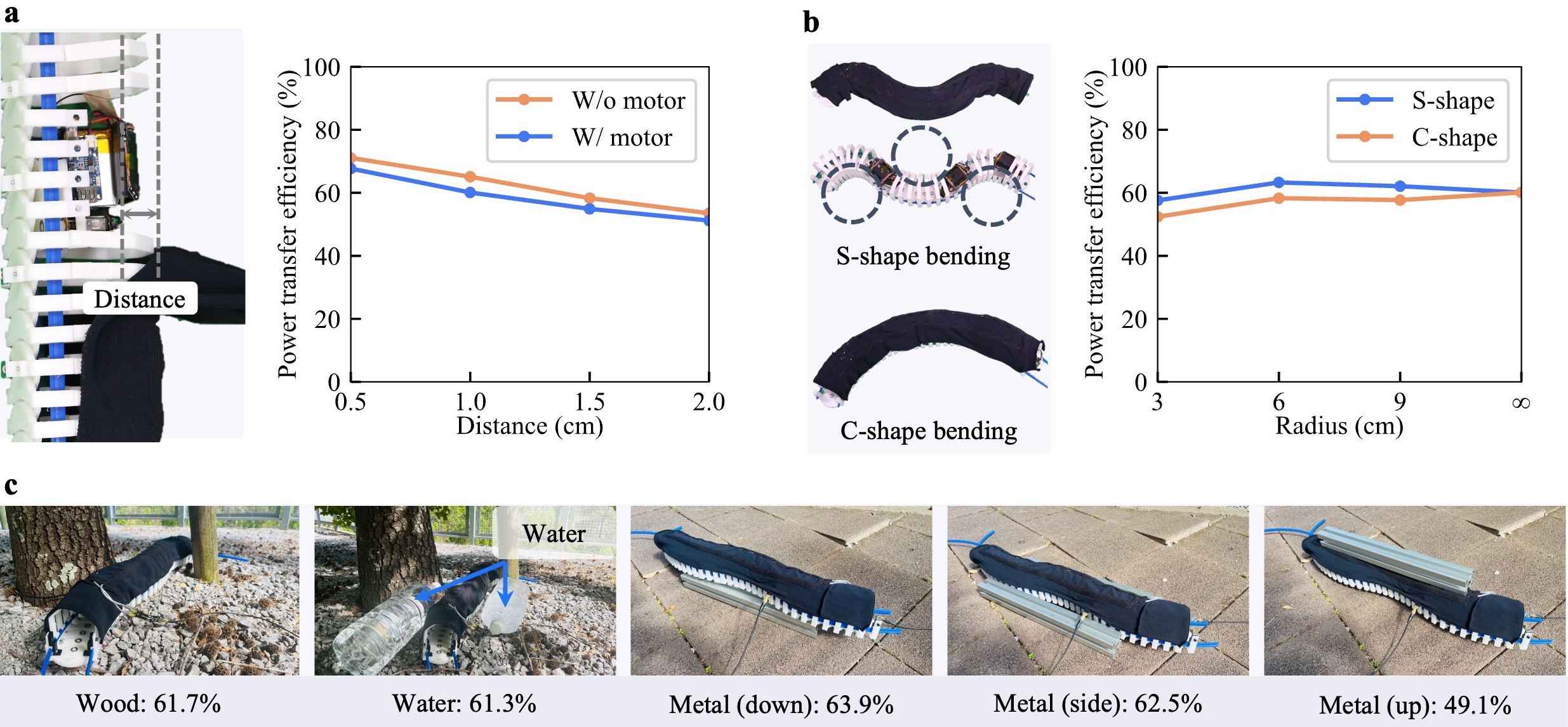
First, we investigate the wireless charging capability of the robot skin by measuring the AC-to-AC power transfer efficiency with respect to the distance between the TX/RX coils, snake bending postures, and different surrounding environments. The efficiency is calculated based on the measured S-parameter obtained from a vector network analyzer (PicoVNA108) [12]. Figure 6a shows the efficiency with or without the joint units for the distance between the TX/RX coils, ranging from to in steps of . The results show that the efficiency is almost the same with or without the joint units, indicating that the TX coil avoids the electromagnetic interference with the metallic motors in the joint units. Moreover, the shorter distance shows the higher efficiency. Here, the distance of is chosen to avoid collisions between the RX coil and the robot skin while keeping the high efficiency of approximately . Then, Figure 6b illustrates the efficiency against the two types of bending posture: S-shape and C-shape with the three bending radius ranging from to in steps of and one straight line. The efficiency is shown to be over for the different bending radius of the S-shape or C-shape bending, owing to the relatively low -factor of the TX coil [13]. Therefore, the joint units are able to stably receive -class power stably during joint bending. Lastly, Figure 6c shows the efficiency against non-metallic (i.e., wood, water) or metallic surrounding environments. The results show that the efficiency is almost the same except when the metallic items are above the TX coil, which causes significant electromagnetic interference with with nearby metallic items. The attachment of a ferromagnetic sheet above the robot skin could mitigate the efficiency drop or electromagnetic interactions [10].
IV-B Simulation-based Accuracy of Serpentine Locomotion
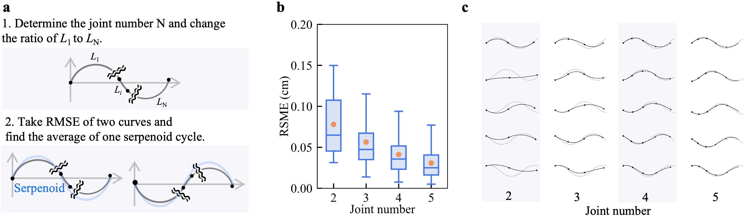
Next, we evaluated the locomotion accuracy of the proposed robot. Under the control scheme described in § III-B, Figure 7 shows the simulation results of the fitting error for the variable-length arc-shaped joint model applied to a serpenoid curve. We set the total robot length to varying the number of arc segments from to . The length of each segment ranges from . As shown in Figure 7a, the serpenoid curve (: , : ) was trimmed to match the robot’s length, and a series of points were plotted at equal intervals along both the robot and the curve. We calculated the root mean square error (RMSE) between these points to quantify the deviation. Figure 7bc presents the RMSE and fitting pattern for the joint number ranging from to , respectively. As the joint number decreases, RMSE increases because fewer joints cause extremely long arc segments with large fitting errors for the serpenoid segment. When the joint number is , the arc model fails to follow the serpenoid, but a joint number greater than achieves approximate fitting accuracy. Considering the trade-off between the fitting accuracy and the motor number, we chose joint units for prototype implementation.
IV-C Locomotion Capability and Speed
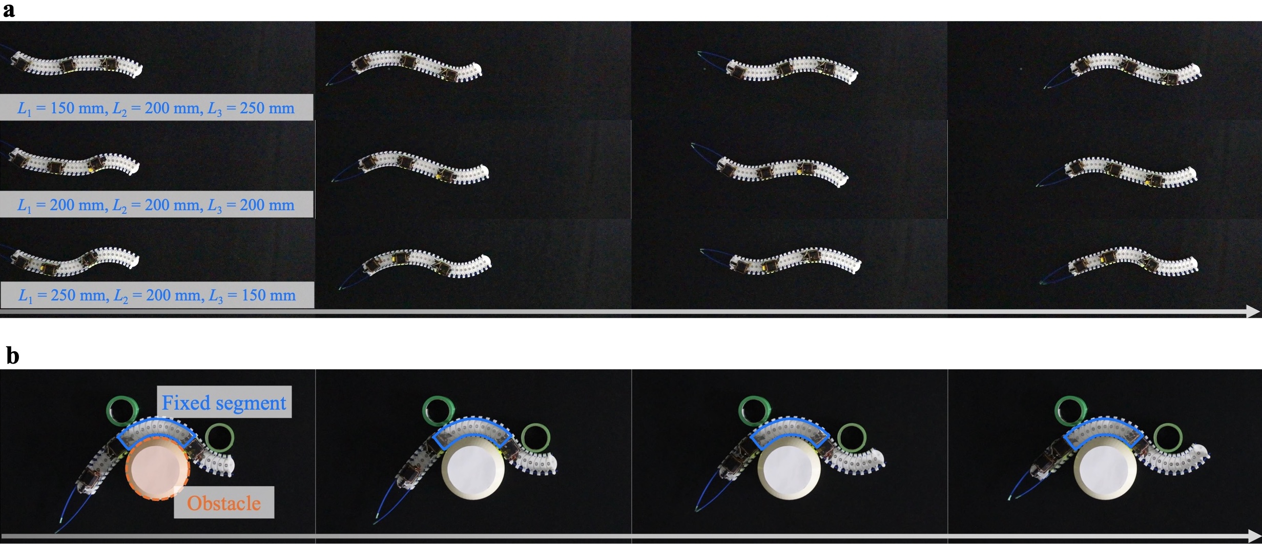
Lastly, we demonstrated two types of locomotion as proofs of concept. Figure 8a shows a joint-position-free serpentine locomotion utilizing our prototype. Based on the control law described in § III-B, the snake robot with different segment lengths moved along a serpenoid curve with and , achieving a relatively fast velocity of . Note that the robot’s velocity remains almost constant when each segment length does not change significantly. Additionally, Figure 8b shows a joint-position-based obstacle-aided locomotion. The prototype was placed in an obstacle-rich environment with three fixed cylinder-shaped obstacles. Following the control law described in § III-C, the robot moved at a slow velocity of , while maintaining the segment shape in contact with the three obstacles.
V CONCLUSIONS
This paper presents the joint-repositionable, inner-wireless snake robot capable of performing multi-joint, lightweight, low-powered locomotion. The repositionable joint units enable underactuated multi-joint bending, in addition to the wireless charging-enables robot skin powering up the repositionable joint units continuously. We studied the locomotion performance in the context of control mechanisms and wireless charging capability, demonstrating joint-repositionable locomotion with a wireless charging capability of .
Our current prototype still has some limitations. First, our current snake robot supports only two types of planar locomotion, whereas the prior snake robots have demonstrated various locomotion modes for navigation in three-dimensional heterogeneous terrains. To address this issue, future research will focus on three key aspects: mechanism, control, and sensing. From a mechanical perspective, the robot mechanism is limited to planar bending. Implementation of multi-directional bending could allow the robot to achieve 3D motion [25]. From a control perspective, the current control strategy supports only simple locomotion, requiring the robot to operate in the controlled environment [26]. Deep reinforcement learning such as sim-to-real could enable dynamic control strategies for real-world environments. On the sensing front, the robot lacks the capability to detect shape deformations caused by external forces. Integrating sensors into the robot skin could improve its adaptability to complex terrains. We strongly believe that our joint-repositionable inner-wireless snake robot could lead to even more practical and capable robot explorers.
ACKNOWLEDGMENT
This work was mainly supported by JST ACT-X JPMJAX23K6, JPMJAX21K9, and JSPS KAKEN 22K21343. The authors would like to thank Fumito Kanada, Takashi Sato, and Fuma Kuroda for their help with our implementation.
References
- [1] R. Hoffstetter, J. Gasc, and C. Gans, “Biology of the reptilia,” Volume, vol. 1, pp. 201–310, 1969.
- [2] B. R. Moon, “Testing an inference of function from structure: snake vertebrae do the twist,” Journal of Morphology, vol. 241, no. 3, pp. 217–225, 1999.
- [3] K. Y. Pettersen, “Snake robots,” Annual Reviews in Control, vol. 44, pp. 19–44, 2017.
- [4] J. Liu, Y. Tong, and J. Liu, “Review of snake robots in constrained environments,” Robotics and Autonomous Systems, vol. 141, p. 103785, 2021.
- [5] P. Liljebäck, K. Y. Pettersen, Ø. Stavdahl, and J. T. Gravdahl, Snake robots: modelling, mechatronics, and control. Springer, 2013.
- [6] X. Qi, H. Shi, T. Pinto, and X. Tan, “A novel pneumatic soft snake robot using traveling-wave locomotion in constrained environments,” IEEE Robotics and Automation Letters, vol. 5, no. 2, pp. 1610–1617, 2020.
- [7] C. Branyan, C. Fleming, J. Remaley, A. Kothari, K. Tumer, R. L. Hatton, and Y. Mengüç, “Soft snake robots: Mechanical design and geometric gait implementation,” in 2017 IEEE International Conference on Robotics and Biomimetics (ROBIO). IEEE, 2017, pp. 282–289.
- [8] Z. Wan, Y. Sun, Y. Qin, E. H. Skorina, R. Gasoto, M. Luo, J. Fu, and C. D. Onal, “Design, analysis, and real-time simulation of a 3d soft robotic snake,” Soft Robotics, vol. 10, no. 2, pp. 258–268, 2023.
- [9] A. R. Plamootil Mathai, T. Stalin, and P. Valvivia y Alvarado, “Flexible fiber inductive coils for soft robots and wearable devices,” IEEE Robotics and Automation Letters, vol. 7, no. 2, pp. 5711–5718, 2022.
- [10] R. Takahashi, T. Sasatani, F. Okuya, Y. Narusue, and Y. Kawahara, “A cuttable wireless power transfer sheet,” Proc. ACM Interact. Mob. Wearable Ubiquitous Technol., vol. 2, no. 4, dec 2018.
- [11] A. Alabsi, A. Hawbani, X. Wang, A. A. Dubai, J. Hu, S. A. Aziz, S. Kumar, L. Zhao, A. V. Shvetsov, and S. H. Alsamhi, “Wireless power transfer technologies, applications, and future trends: A review,” IEEE Transactions on Sustainable Computing, pp. 1–18, 2024.
- [12] M. Zargham and P. G. Gulak, “Maximum achievable efficiency in near-field coupled power-transfer systems,” IEEE Transactions on Biomedical Circuits and Systems, vol. 6, no. 3, pp. 228–245, 2012.
- [13] R. Takahashi, W. Yukita, T. Yokota, T. Someya, and Y. Kawahara, “Meander coil++: A body-scale wireless power transmission using safe-to-body and energy-efficient transmitter coil,” in Proceedings of the 2022 CHI Conference on Human Factors in Computing Systems, ser. CHI ’22. New York, NY, USA: Association for Computing Machinery, 2022.
- [14] R. Takahashi, W. Yukita, T. Sasatani, T. Yokota, T. Someya, and Y. Kawahara, “Twin meander coil: Sensitive readout of battery-free on-body wireless sensors using body-scale meander coils,” Proc. ACM Interact. Mob. Wearable Ubiquitous Technol., vol. 5, no. 4, dec 2022.
- [15] M. D. Dickey, R. C. Chiechi, R. J. Larsen, E. A. Weiss, D. A. Weitz, and G. M. Whitesides, “Eutectic gallium-indium (egain): A liquid metal alloy for the formation of stable structures in microchannels at room temperature,” Advanced Functional Materials, vol. 18, no. 7, pp. 1097–1104, 2008.
- [16] R. Takahashi, E. Whitmire, R. Boldu, S. Ng, W. Kienzle, and H. Benko, “picoring: battery-free rings for subtle thumb-to-index inpu,” in Proceedings of the 37th Annual ACM Symposium on User Interface Software and Technology, ser. UIST ’24. New York, NY, USA: Association for Computing Machinery, 2024.
- [17] R. Takahashi, M. Fukumoto, C. Han, T. Sasatani, Y. Narusue, and Y. Kawahara, “Telemetring: A batteryless and wireless ring-shaped keyboard using passive inductive telemetry,” ser. UIST ’20. New York, NY, USA: Association for Computing Machinery, 2020, p. 1161–1168.
- [18] M. Sato, M. Fukaya, and T. Iwasaki, “Serpentine locomotion with robotic snakes,” IEEE Control Systems Magazine, vol. 22, no. 1, pp. 64–81, 2002.
- [19] A. A. Transeth, R. I. Leine, C. Glocker, K. Y. Pettersen, and P. Liljebäck, “Snake robot obstacle-aided locomotion: Modeling, simulations, and experiments,” IEEE Transactions on Robotics, vol. 24, no. 1, pp. 88–104, 2008.
- [20] S. Ma, “Analysis of snake movement forms for realization of snake-like robots,” in Proceedings 1999 IEEE International Conference on Robotics and Automation (Cat. No.99CH36288C), vol. 4, 1999, pp. 3007–3013 vol.4.
- [21] H. Yamada and S. Hirose, “Approximations to continuous curves of active cord mechanism made of arc-shaped joints or double joints,” in 2010 IEEE International Conference on Robotics and Automation. IEEE, 2010, pp. 703–708.
- [22] M. Sato, M. Fukaya, and T. Iwasaki, “Serpentine locomotion with robotic snakes,” IEEE Control Systems Magazine, vol. 22, no. 1, pp. 64–81, 2002.
- [23] T. Takanashi, M. Nakajima, T. Takemori, and M. Tanaka, “Obstacle-aided locomotion of a snake robot using piecewise helixes,” IEEE Robotics and Automation Letters, vol. 7, no. 4, pp. 10 542–10 549, 2022.
- [24] T. Kano, R. Yoshizawa, and A. Ishiguro, “Tegotae-based decentralised control scheme for autonomous gait transition of snake-like robots,” Bioinspiration & biomimetics, vol. 12, no. 4, p. 046009, 2017.
- [25] U. Mavinkurve, A. Kanada, S. A. Tafrishi, K. Honda, Y. Nakashima, and M. Yamamoto, “Geared rod-driven continuum robot with woodpecker-inspired extension mechanism and imu-based force sensing,” IEEE Robotics and Automation Letters, vol. 9, no. 1, pp. 135–142, 2023.
- [26] X. Qi, D. Chen, Z. Li, and X. Tan, “Back-stepping experience replay with application to model-free reinforcement learning for a soft snake robot,” IEEE Robotics and Automation Letters, vol. 9, no. 9, pp. 7517–7524, 2024.