Probing g-tensor reproducibility and spin-orbit effects in planar silicon hole quantum dots
Abstract
In this work, we probe the sensitivity of hole-spin properties to hole occupation number in a planar silicon double-quantum dot device fabricated on a 300 mm integrated platform. Using DC transport measurements, we investigate the g-tensor and spin-relaxation induced leakage current within the Pauli spin-blockade regime as a function of magnetic-field orientation at three different hole occupation numbers. We find the g-tensor and spin-leakage current to be highly anisotropic due to light-hole/heavy-hole mixing and spin-orbit mixing, but discover the anisotropies to be relatively insensitive to the dot hole number. Furthermore, we extract the dominant inter-dot spin-orbit coupling mechanism as surface Dresselhaus, with an in-plane orientation parallel to transport and magnitude 300 neV. Finally, we observe a strong correlation between the g-factor difference () between each dot and the spin-leakage current anisotropy, as a result of providing an additional spin-relaxation pathway. Our findings indicate that hole-spin devices are not as sensitive to precise operating conditions as anticipated. This has important implications optimizing spin control and readout based on magnetic-field direction, together with tuning large arrays of QDs as spin-qubits.
UNSW Physics] School of Physics, The University of New South Wales, Sydney NSW 2052, Australia \alsoaffiliation[RIKEN] Present address: RIKEN, 2-1 Hirosawa, Wako, Saitama 351-0198, Japan \alsoaffiliation[Equal]These authors contributed equally to this work. UNSW Physics] School of Physics, The University of New South Wales, Sydney NSW 2052, Australia \alsoaffiliation[Equal]These authors contributed equally to this work. UNSW Physics] School of Physics, The University of New South Wales, Sydney NSW 2052, Australia UNSW Physics] School of Physics, The University of New South Wales, Sydney NSW 2052, Australia IMEC] IMEC, Remisebosweg 1, B-3001 Leuven, Belgium IMEC] IMEC, Remisebosweg 1, B-3001 Leuven, Belgium IMEC] IMEC, Remisebosweg 1, B-3001 Leuven, Belgium IMEC] IMEC, Remisebosweg 1, B-3001 Leuven, Belgium UNSW Physics] School of Physics, The University of New South Wales, Sydney NSW 2052, Australia UNSW Physics] School of Physics, The University of New South Wales, Sydney NSW 2052, Australia \abbreviations
Spin-qubits in semiconductor dots provide an industry-compatible platform to achieve future up-scaling through high packing densities 1, 2, 3.
Numerous breakthroughs have been demonstrated with electron spin-qubits in silicon dots, including record gate fidelities (99.95 %), high temperature operation and AC electric-field control for spin-state manipulation 4, 5, 6, 7, 8, 9. Recent interest in hole spins has been sparked by their intrinsic strong spin-orbit interaction (SOI) which enables fast all-electric control, the absence of a valley degree of freedom and a weak hyperfine interaction. 10, 11, 12, 13, 14, 9, 15, 16, 17, 18.
These advantages have permitted a plethora of hole-spin qubit advancements, such as ultra-fast singlet-triplet operation (400 MHz), tunable spin-orbit effects and coherent shuttling across large arrays 19, 20, 21.
Pauli spin-blockade is a commonly used technique for spin-readout within a double-dot, but in hole systems it is heavily influenced by the SOI 22, 23. This results in unwanted spin-rotations and reduced fidelity when holes tunnel between dots. The strong SOI also gives rise to variations in the hole g-tensor on each dot due to differences in the local electronic environment, such as the dot hole number, local strain and gate biases 24, 25, 26, 27. While a g-factor difference () between dots is useful for driving rapid spin control in singlet-triplet qubits (which rely on differences in the Zeeman-splitting to drive qubit rotations) it can also lead to performance and scalability issues 28, 26, 29. For example, it is not clear if the spin properties for one particular dot occupation remain the same when the number of holes is varied.
Probing the SOI mechanism using spin-blockade based qubit readout via anisotropy of both the spin-orbit coupling () and hole g-tensor is also important for improving control and fidelity when scaling to larger numbers of qubits 30, 31, 32. This is because, while a strong SOI enhances the coupling to more effectively drive the qubit spin state, it also couples the qubit to electrical noise, reducing the coherence time. Unfortunately, is a difficult parameter to measure 33, 34. One approach is to extract from singlet-triplet level anti-crossings, but this is technically challenging since it requires fast pulsed gate operations 35, 36. A simpler method to evaluate and hole g-tensor anisotropy would be highly desirable.
Here, we take advantage of simple DC transport measurements of spin-leakage current () to characterise the dominant mechanism, together with spin-resonance to probe the anisotropic g-tensor of a silicon hole double-dot at three different dot occupations, without fast pulses or time resolved measurements. is extracted by monitoring the 3D magnetic-field dependence of within the Pauli spin-blocked regime. We utilize continuous-wave electric-dipole spin-resonance (EDSR) to extract the dot g-tensor () in all planes and dot occupations as well as in-plane. Our results allow comparisons between the dependence of , and hole g-tensor anisotropy on the magnetic-field orientation when varying the hole number, to provide key information on the reproducibility and robustness of the spin properties for a path towards scalable hole-spin qubit architectures.
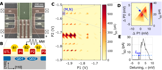
(A) SEM image of our planar Si-MOS dot device gate layout. (B) Device cross-section, where QD1 and QD2 are formed under plungers P1 and P2, with tunnelling barriers B1, B2 and B3 defining the potential longitudinally, and confinement gate C laterally. Holes are loaded from the STL reservoir and tunnel through the double-dot to the STR/P3 2D hole-gas along the [110] direction. (C) A charge stability map with bias triangles to confirm a well-defined double-dot structure. A periodic array of bias triangles enables a systematic study of different charge occupations. (D) An enlargement of a measured bias triangle as highlighted in Figure 1C. (E) A line-cut of detuning vs , where transport is measured along the detuning axis given by the blue dashed line in Figure 1D. A finite leakage current, , (marked by a blue star on the graph) is measured at the base of the bias triangle due to singlet-triplet mixing within the Pauli spin-blockade regime.
Figure 1A shows an SEM image of the planar silicon metal-oxide-semiconductor device gate layout, fabricated using a flexible 300 mm process with electron beam lithography for patterning the pitch-critical areas and optical lithography for defining larger features37. The device cross-section is displayed in Figure 1B, where the dots (QD1 and QD2) are vertically defined along the [100] growth direction and hole transport () occurs in the [110] direction. The dots are created under plunger gates P1 and P2, with gates B1 and B3 forming barriers to control the tunnelling between each dot and the reservoir. Gate B2 acts as the interdot barrier for controlling the tunnel rate within the double-dot via the tunnel coupling (). A continuous AC microwave tone is applied on B2 for performing EDSR to extract the effective g-factor.
Double-dot formation is confirmed by a periodic array of bias triangles in a charge stability map (Figure 1C) for a fixed source-drain bias of 2 mV. In Figure 1C, each bias triangle horizontal row represents a fixed dot occupancy for QD2 while the occupation of QD1 varies. Since the double-dot hole number is unknown, we focus on a single bias triangle row and vary the number of holes on QD1 for a fixed QD2 occupation, with the initial hole number denoted by (M,N). The bias triangle base marked by the blue star in Figure 1D shows Pauli spin-blockade for the lowest hole occupancy studied due to prohibited (odd, odd) to (even, even) hole transitions. Pauli spin-blockade can be lifted by spin-relaxation, producing a finite spin-leakage current () as a result of various spin non-conserving processes. We observe an value of 6 pA, as shown by the line-cut in Figure 1E (blue star) along the detuning axis of the bias triangle in Figure 1D. The spin-leakage current in Figure 1E includes contributions from SOI effects as well as spin-flip cotunneling, which must be separated in order to obtain information on the strength of the SOI from spin-orbit coupling.
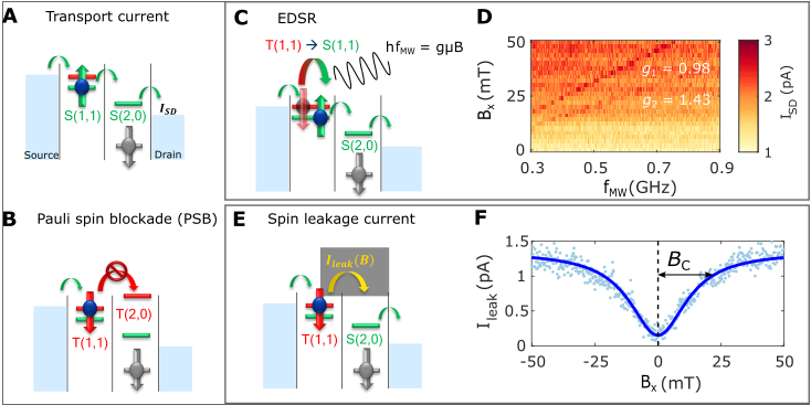
(A) Transport is allowed through the double-dot via the singlet () like states (1,1) and (0,2). (B) Transport is prohibited via the triplet like () state (1,1) to (2,0) due to spin conservation and Pauli exclusion. (C) A diagram showing how an AC electric-field frequency () resonant with the Zeeman-splitting lifts Pauli spin-blockade via EDSR. (D) as a function of and shows with two distinct resonant frequencies as a result of g-factors and from dots QD1 and QD2 respectively. (E) Pauli spin-blockade can also be lifted by the coupling between an applied B-field and the SOI as a result of S-T state mixing, producing a finite . (F) as a function of is fitted to a characteristic inverse Lorentzian to extract a critical magnetic-field = 12.6 mT, quantifying the relative spin-orbit strength.
To study the spin-orbit effects we operate our device in the (1,1)-(2,0) equivalent hole transition for Pauli spin-blockade, where (M,N) indicates the effective dot occupation. Double-dot transport is allowed between the singlet (1,1)-(2,0) like states (Figure 2A) and blocked between the triplet and singlet like states (1,1)-(2,0) (Figure 2B) owing to the Pauli-exclusion principle and energy inaccessibility of (2,0). The diagram in Figure 2C displays how EDSR is achieved by an AC microwave tone () driving transitions between the - states to lift spin-blockade according to , where is the hole g-factor, is the Bohr magneton and is the magnetic-field along (). Figure 2D shows as a function of and for the spin-blocked region marked by the blue star in Figure 1E. Two distinct lines are observed in the colourmap where is increased due to hole-spin resonance, yielding values of =0.98 and =1.43 from the line gradients.
The coupling between and spin-orbit coupling () can be probed by the magnetic-field dependence of (shown schematically in Figure 2E) since represents the amount of SOI mixing between the and Zeeman-split states (/) 38. We measure as a function of in the Figure 2F line plot and observe a rapid increase in with increasing magnetic-field. Information on the dependence of can also be extracted from the off-resonance in Figure 2D, however a current offset must be subtracted from in Figure 2D to obtain . For 40 mT, saturates as a product of optimally coupled - states leading to a maximum spin-relaxation rate39. This maximum spin-relaxation rate, or , is set by the reservoir/interdot tunnel rates and . According to Figure 2F nuclear hyperfine interactions are weak, since hyperfine mixing typically produce a characteristic sharp peak in centered around =0, which is not observed. The absence of strong hyperfine interactions is consistent with the atomic p-orbital nature of holes.
To quantify the spin-orbit mixing, we fit the experimental data in Figure 2F to the expected form of as a function of in the Pauli spin-blockade regime
| (1) |
The saturation current due to spin-orbit mixing only is given by , is the current offset at and is the critical magnetic-field that parameterises the spin-orbit mixing strength. Based on this model, we extract = 12.6 mT for , orientated along [10] (see Supplementary Section IV for fitting details). The orientation of is important, since is highly dependent on any anisotropic effects in both the strength of spin-orbit mixing () and the dot g-tensor, which we discuss below.
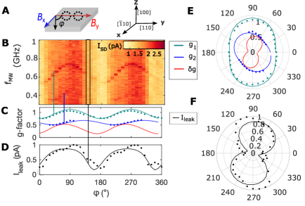
(A) Schematics depicting rotation relative to crystal axes.(B) Electric-dipole spin-resonance (EDSR) as a function of . is aligned along the transport direction ([110]), with perpendicular ([10]). (C) Extracted effective g-factors as a function of , where is calculated via . (D) is extracted from the average for a given . (E) To better visualize the anisotropies, polar plots are generated of , and , as well as in (F) to compare.
To study the effective g-factor and anisotropy we measure as a function of orientation as shown schematically in Figure 3A for an in-plane rotation. By performing EDSR, we are able to distinguish two hole-spin resonance lines in Figure 3B as a function and angle () for a fixed = 50 mT. Two lines are observed as a result of QD1 and QD2 possessing site-dependent g-factors, and , which are extracted and plotted in Figure 3C, along with the g-factor difference (). is obtained using the average in Figure 3B (minus an offset due to other spin-flip processes) and plotted in Figure 3D as a function of . To aid in visualizing the correlation between g-factor and anisotropy, polar plots are generated of , and in Figure 3D and in Figure 3E. A 45∘ shift in the effective g-factor orientation is present between and in 3E, attributed to variations in the local electronic environment surrounding each dot, together with strain and differences in confinement. Comparisons between and anisotropy in Figure 3E 3F yield a strong correlation, suggesting that contributes to spin-flip tunneling.
The mechanism linking and has been reported as a coherent mixing of the non-polarized and like states, where a larger results in faster spin-relaxation to as a consequence of the varying phase difference and enhanced mixing between the two states 40. The correlation between the and maximum is believed to arise due to a large splitting between - and -, and since the states are strongly coupled, faster spin-relaxation occurs between all and states.
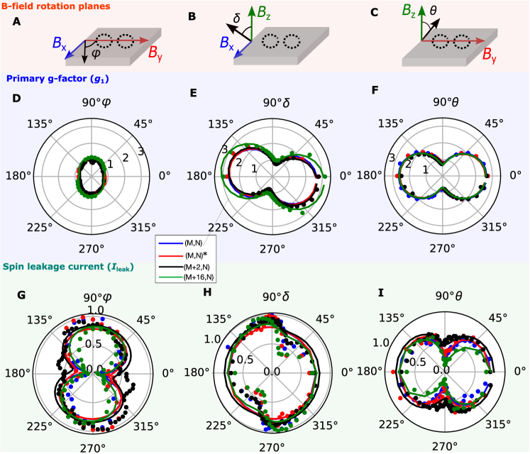
(A-C) Schematics defining rotations in the , and planes. Polar plots of QD1 effective g-factor () (D-F) and (G-I) for three different hole occupation numbers: (M, N)(blue), (M, N)* with different (red), (M+2, N) (black) and (M+16, N)(green). is extracted via EDSR, while is measured using the off-resonance . The points and lines denote extracted data and fitting respectively.
To investigate the impact of varying the hole number on the g-tensor and we rotate in all three orthogonal planes , and (Figures 4A-C) to extract the effective g-factor and for three different dot occupations of QD1. The anisotropy of in Figures 4D-F is consistent at each dot occupation with very little variation in magnitude and orientation upon changing the number of holes. We also observe a similar insensitivity to changes in hole occupation number for in Figures 4G-I. Notably, when comparing the measured data for each plane in Figures 4D-I, and exhibit a similar dependence on the orientation of .
The calculated values of at each hole occupation are consistent with the extracted , which are expected to be approximately proportional 39. The direction of that resulted in the minimum () corresponds to strongly aligned to the transport direction, which suggests that the surface Dresselhaus SOI is dominant, rather than Rashba SOI, since Rashba acts in-plane and perpendicular to transport41, 42. As such, choosing would yield strong electrical driving of the qubit spin state, while would improve coherence but limit control. In our double-dot, we assign the strong Dresselhaus interaction to variations in the inter-atomic spacing at the SiO2 interface, breaking inversion symmetry and generating an electric-field which couples to the hole-spin in-plane.
One of the advantages of a g-tensor which is largely independent from the hole number and gate bias is that strain effects from electric-field gradients can be isolated. As such, from the small tilt where in Figure 4E, we assign the origin to non-uniform strain at the SiO2 interface 27. The presence of non-uniform strain is further supported by the in-plane site-dependent g-factors of both dots shown in Figure 3E, which modulate the g-tensor at each dot.
In summary, the extracted g-tensor was found to be highly anisotropic, with a large out-of plane 2.6 and a small in-plane 0.8. A correlation between the g-tensor and spin-leakage current anisotropy was observed, which impacted the magnitude of and spin-orbit - mixing. We determined the orientation to be aligned mostly parallel to transport, a characteristic of surface Dresselhaus SOI, in contrast to Rashba SOI that has largely been considered in hole dots. We also observed a strong correlation between and as a result of mixing between and the non-polarized state. Comparisons between three different dot occupations yielded little to no-effect on the g-tensor and spin-relaxation, meaning the spin properties of our hole-dots are resilient to changes in hole number and gate bias.
0.1 Experimental Methods
The Si-MOS device consists of a three-layer gate structure with a sub-50 nm width and 5 nm isolation layer enables a tighter QD confinement potential. The measurements were performed in a BlueFors LD250 dilution refrigerator with a base temperature of 8 mK and an approximate electron temperature of 120 mK. Magnetic-field rotations to study the anisotropy in spin-leakage current and g-factor were achieved via a 6T-1T-1T vector magnet. The sample was mounted on a PCB with a LPF on the DC lines ( 130 kHz), and bias-tees on the RF lines (R=1.2 k, C = 1 nF) in order to apply microwave tones. Voltages for the DC were sourced through a Quantum Machines QDAC and an RS SGS100A to generate microwaves for EDSR. The spin-leakage was current converted into a voltage via a low-noise high-stability Basel instruments I-V converter with 300 Hz, and measured by a Keithley K2000 multi-meter. {acknowledgement} This work was funded by the Australian Research Council under projects LP200100019, DP200100147 and IL230100072.
References
- Rotta et al. 2017 Rotta, D.; Sebastiano, F.; Charbon, E.; Prati, E. Quantum information density scaling and qubit operation time constraints of CMOS silicon-based quantum computer architectures. npj Quantum Information 2017, 3, 26
- Vinet et al. 2018 Vinet, M. et al. Towards scalable silicon quantum computing. IEDM 2018, 3, 651–654
- de Leon et al. 2021 de Leon, N. P.; Itoh, K. M.; Kim, D.; Mehta, K. K.; Northup, T. E.; Paik, H.; Palmer, B. S.; Samarth, N.; Sangtawesin, S.; Steuerman, D. W. Materials challenges and opportunities for quantum computing hardware. Science 2021, 372, 282
- Lim et al. 2009 Lim, W. H.; Huebl, H.; Willems van Beveren, L. H.; Rubanov, S.; Spizzirri, P. G.; Angus, S. J.; Clark, R. G.; Dzurak, A. S. Electrostatically defined few-electron double quantum dot in silicon. 2009, 94, 173502
- Fogarty et al. 2018 Fogarty, M. A.; Chan, K. W.; Hensen, B.; Huang, W.; Tanttu, T.; Yang, C. H.; Laucht, A.; Veldhorst, M.; Hudson, F. E.; Itoh, K. M.; Culcer, D.; Ladd, T. D.; Morello, A.; Dzurak, A. S. Integrated silicon qubit platform with single-spin addressability, exchange control and single-shot singlet-triplet readout. Nature Communications 2018, 9, 4370
- Huang et al. 2024 Huang, J. Y. et al. High-fidelity spin qubit operation and algorithmic initialization above 1 K. Nature 2024, 627, 772–777
- Yang et al. 2020 Yang, C. H.; Leon, R. C. C.; Hwang, J. C. C.; Saraiva, A.; Tanttu, T.; Huang, W.; Camirand Lemyre, J.; Chan, K. W.; Tan, K. Y.; Hudson, F. E.; Itoh, K. M.; Morello, A.; Pioro-Ladrière, M.; Laucht, A.; Dzurak, A. S. Operation of a silicon quantum processor unit cell above one kelvin. Nature 2020, 580, 350–354
- Gilbert et al. 2023 Gilbert, W. et al. On-demand electrical control of spin qubits. Nat. Nanotechnol. 2023, 18, 131–136
- Camenzind et al. 2022 Camenzind, L. C.; Geyer, S.; Fuhrer, A.; Warburton, R. J.; Zumbühl, D. M.; Kuhlmann, A. V. A hole spin qubit in a fin field-effect transistor above 4 kelvin. Nature Electronics 2022, 5, 178–183
- De Greve et al. 2011 De Greve, K.; McMahon, P. L.; Press, D.; Ladd, T. D.; Bisping, D.; Schneider, C.; Kamp, M.; Worschech, L.; Höfling, S.; Forchel, A.; Yamamoto, Y. Ultrafast coherent control and suppressed nuclear feedback of a single quantum dot hole qubit. Nature Phys 2011, 7, 872–878
- Lawrie et al. 2020 Lawrie, W. I. L.; Hendrickx, N. W.; van Riggelen, F.; Russ, M.; Petit, L.; Sammak, A.; Scappucci, G.; Veldhorst, M. Spin Relaxation Benchmarks and Individual Qubit Addressability for Holes in Quantum Dots. Nano Letters 2020, 20, 7237–7242
- Bulaev and Loss 2007 Bulaev, D. V.; Loss, D. Electric Dipole Spin Resonance for Heavy Holes in Quantum Dots. Phys. Rev. Lett. 2007, 98, 097202
- Watzinger et al. 2018 Watzinger, H.; Kukučka, J.; Vukušić, L.; Gao, F.; Wang, T.; Schäffler, F.; Zhang, J.-J.; Katsaros, G. A germanium hole spin qubit. Nat Commun 2018, 9, 3902
- Hendrickx et al. 2020 Hendrickx, N. W.; Franke, D. P.; Sammak, A.; Scappucci, G.; Veldhorst, M. Fast two-qubit logic with holes in germanium. 2020, 577, 487–491
- Maurand et al. 2016 Maurand, R.; Jehl, X.; Kotekar-Patil, D.; Corna, A.; Bohuslavskyi, H.; Laviéville, R.; Hutin, L.; Barraud, S.; Vinet, M.; Sanquer, M.; De Franceschi, S. A CMOS silicon spin qubit. Nature Communications 2016, 7, 13575
- Hendrickx et al. 2021 Hendrickx, N. W.; Lawrie, W. I. L.; Russ, M.; van Riggelen, F.; de Snoo, S. L.; Schouten, R. N.; Sammak, A.; Scappucci, G.; Veldhorst, M. A four-qubit germanium quantum processor. 2021, 591, 580–585
- Geyer et al. 2024 Geyer, S.; Hetényi, B.; Bosco, S.; Camenzind, L. C.; Eggli, R. S.; Fuhrer, A.; Loss, D.; Warburton, R. J.; Zumbühl, D. M.; Kuhlmann, A. V. Two-qubit logic with anisotropic exchange in a fin field-effect transistor. Nature Physics 2024, 20, 1152–1157
- Bosco et al. 2023 Bosco, S.; Geyer, S.; Camenzind, L. C.; Eggli, R. S.; Fuhrer, A.; Warburton, R. J.; Zumbühl, D. M.; Egues, J. C.; Kuhlmann, A. V.; Loss, D. Phase driving hole spin qubits. Phys.Rev. Lett. 2023, 131., 197001
- Liles et al. 2024 Liles, S. D. et al. A singlet-triplet hole-spin qubit in MOS silicon. ’Nat Commun’ 2024, 15, 7690
- Froning et al. 2021 Froning, F. N. M.; Camenzind, L. C.; van der Molen, O. A. H.; Li, A.; Bakkers, E. P. A. M.; Zumbühl, D. M.; Braakman, F. R. Ultrafast hole spin qubit with gate-tunable spin–orbit switch functionality. Nature Nanotechnology 2021, 16, 308–312
- Wang et al. 2024 Wang, C.-A.; others Operating semiconductor quantum processors with hopping spins. Science 2024, 385, ado5915
- Nadj-Perge et al. 2010 Nadj-Perge, S.; Frolov, S. M.; Bakkers, E. P. A. M.; Kouwenhoven, L. P. Spin–orbit qubit in a semiconductor nanowire. Nature 2010, 468, 1084–1087
- Hillier et al. 2021 Hillier, J.; Ono, K.; Ibukuro, K.; Liu, F.; Li, Z.; Husain Khaled, M.; Nicholas Rutt, H.; Tomita, I.; Tsuchiya, Y.; Ishibashi, K.; Saito, S. Probing hole spin transport of disorder quantum dots via Pauli spin-blockade in standard silicon transistors. IOP Nanotechnology 2021, 32
- Ares et al. 2013 Ares, N.; Golovach, V. N.; Katsaros, G.; Stoffel, M.; Fournel, F.; Glazman, L. I.; Schmidt, O. G.; Franceschi, S. D. Nature of Tunable Hole g Factors in Quantum Dots. Phys. Rev. Lett. 2013, 5
- Srinivasan et al. 2016 Srinivasan, A.; Hudson, K. L.; Miserev, D.; Yeoh, L. A.; Klochan, O.; Muraki, K.; Hirayama, Y.; Sushkov, O. P.; Hamilton, A. R. Electrical control of the sign of the g factor in a GaAs hole quantum point contact. Physical Review B 2016, 94, 041406
- Bogan et al. 2017 Bogan, A.; Studenikin, S.; Korkusinski, M.; Aers, G.; Gaudreau, L.; Zawadzki, P.; Sachrajda, A.; Tracy, L.; Reno, J.; Hargett, T. Consequences of Spin-Orbit Coupling at the Single Hole Level: Spin-Flip Tunneling and the Anisotropic g Factor. Physical Review Letters 2017, 118
- Liles et al. 2021 Liles, S. D.; Martins, F.; Miserev, D. S.; Kiselev, A. A.; Thorvaldson, I. D.; Rendell, M. J.; Jin, I. K.; Hudson, F. E.; Veldhorst, M.; Itoh, K. M.; Sushkov, O. P.; Ladd, T. D.; Dzurak, A. S.; Hamilton, A. R. Electrical control of the g tensor of the first hole in a silicon MOS quantum dot. Physical Review B 2021, 104, 235303
- Brauns et al. 2016 Brauns, M.; Ridderbos, J.; Li, A.; Bakkers, E. P. A. M.; Zwanenburg, F. A. Electric-field dependent g -factor anisotropy in Ge-Si core-shell nanowire quantum dots. Physical Review B 2016, 93, 121408
- Jirovec et al. 2021 Jirovec, D. et al. A singlet-triplet hole spin qubit in planar Ge. Nature Materials 2021, 20, 1106–1112
- Nadj-Perge et al. 2010 Nadj-Perge, S.; Frolov, S. M.; van Tilburg, J. W. W.; Danon, J.; Nazarov, Y. V.; Algra, R.; Bakkers, E. P. A. M.; Kouwenhoven, L. P. Disentangling the effects of spin-orbit and hyperfine interactions on spin blockade. Physical Review B 2010, 81, 201305
- Nadj-Perge et al. 2012 Nadj-Perge, S.; Pribiag, V. S.; van den Berg, J. W. G.; Zuo, K.; Plissard, S. R.; Bakkers, E. P. A. M.; Frolov, S. M.; Kouwenhoven, L. P. Spectroscopy of Spin-Orbit Quantum Bits in Indium Antimonide Nanowires. Physical Review Letters 2012, 108, 166801
- Wang et al. 2018 Wang, J.-Y.; Huang, G.-Y.; Huang, S.; Xue, J.; Pan, D.; Zhao, J.; Xu, H. Anisotropic Pauli Spin-Blockade Effect and Spin-Orbit Interaction Field in an InAs Nanowire Double Quantum Dot. Nano Lett 2018, 18, 4741–4747
- Harvey-Collard et al. 2019 Harvey-Collard, P.; Jacobson, N. T.; Bureau-Oxton, C.; Jock, R. M.; Srinivasa, V.; Mounce, A. M.; Ward, D. R.; Anderson, J. M.; Manginell, R. P.; Wendt, J. R.; Pluym, T.; Lilly, M. P.; Luhman, D. R.; Pioro-Ladrière, M.; Carroll, M. S. Spin-orbit Interactions for Singlet-Triplet Qubits in Silicon. Physical Review Letters 2019, 122, 217702
- tan 2019 Controlling Spin-Orbit Interactions in Silicon Quantum Dots Using Magnetic Field Direction. Physical Review X 2019, 9, 021028
- Shevchenko et al. 2020 Shevchenko, S.; Ashhab, S.; Nori, F. Landau–Zener–Stückelberg interferometry. Physics Reports 2020, 492, 1–30
- Higginbotham et al. 2019 Higginbotham, A. P.; Larsen, T. W.; Yao, J.; Yan, H.; Lieber, C. M.; Marcus, C. M.; Kuemmeth, F. Hole Spin Coherence in a Ge/Si Heterostructure Nanowire. Nano Letters 2019, 14, 3582–3586
- 37 Li, R.; Stuyck, N. I. D.; Kubicek, S.; Jussot, J.; Chan, B. T.; Mohiyaddin, F. A.; Elsayed, A.; Shehata, M.; Simion, G.; Godfrin, C.; Canvel, Y.; Ivanov, T.; Goux, L.; Govoreanu, B.; Radu, I. P. A flexible 300 mm integrated Si MOS platform for electron- and hole-spin qubits exploration. IEDM 38.3.1–38.3.4
- Zarassi et al. 2017 Zarassi, A.; Su, Z.; Danon, J.; Schwenderling, J.; Hocevar, M.; Nguyen, B. M.; Yoo, J.; Dayeh, S. A.; Frolov, S. M. Magnetic field evolution of spin blockade in Ge/Si nanowire double quantum dots. Phys. Rev. B 2017, 95, 155416
- Danon and Nazarov 2009 Danon, J.; Nazarov, Y. V. Pauli spin blockade in the presence of strong spin-orbit coupling. Physical Review B 2009, 80, 041301
- Jirovec et al. 2022 Jirovec, D.; Mutter, P. M.; Hofmann, A.; Crippa, A.; Rychetsky, M.; Craig, D. L.; Kukucka, J.; Martins, F.; Ballabio, A.; Ares, N.; Chrastina, D.; Isella, G.; Burkard, G.; Katsaros, G. Dynamics of Hole Singlet-Triplet Qubits with Large -Factor Differences. Phys. Rev. Lett. 2022, 128, 126803
- Rashba 2005 Rashba, E. I. Spin Dynamics and Spin Transport. Journal of Superconductivity 2005, 18, 137–144
- Kloeffel et al. 2018 Kloeffel, C.; Rančić, M. J.; Loss, D. Direct Rashba spin-orbit interaction in Si and Ge nanowires with different growth directions. Physical Review B 2018, 97, 235422