CRT-Fusion: Camera, Radar, Temporal Fusion Using Motion Information for 3D Object Detection
Abstract
Accurate and robust 3D object detection is a critical component in autonomous vehicles and robotics. While recent radar-camera fusion methods have made significant progress by fusing information in the bird’s-eye view (BEV) representation, they often struggle to effectively capture the motion of dynamic objects, leading to limited performance in real-world scenarios. In this paper, we introduce CRT-Fusion, a novel framework that integrates temporal information into radar-camera fusion to address this challenge. Our approach comprises three key modules: Multi-View Fusion (MVF), Motion Feature Estimator (MFE), and Motion Guided Temporal Fusion (MGTF). The MVF module fuses radar and image features within both the camera view and bird’s-eye view, thereby generating a more precise unified BEV representation. The MFE module conducts two simultaneous tasks: estimation of pixel-wise velocity information and BEV segmentation. Based on the velocity and the occupancy score map obtained from the MFE module, the MGTF module aligns and fuses feature maps across multiple timestamps in a recurrent manner. By considering the motion of dynamic objects, CRT-Fusion can produce robust BEV feature maps, thereby improving detection accuracy and robustness. Extensive evaluations on the challenging nuScenes dataset demonstrate that CRT-Fusion achieves state-of-the-art performance for radar-camera-based 3D object detection. Our approach outperforms the previous best method in terms of NDS by , while also surpassing the leading approach in mAP by . These significant improvements in both metrics showcase the effectiveness of our proposed fusion strategy in enhancing the reliability and accuracy of 3D object detection.
1 Introduction
3D object detection plays a crucial role in autonomous vehicles and robotics, leveraging sensors such as lidar, cameras, and radar to localize and classify objects in the environment. Extensive research has been conducted to explore various strategies for improving detection accuracy and robustness. One prominent approach is the integration of data across multiple timestamps, which aims to mitigate the inherent limitations associated with relying solely on instantaneous data. By incorporating historical information, this approach provides a more robust perception of the environment, addressing the challenges of incomplete data caused by occlusions, sensor failures, and other factors.
Numerous studies have investigated the utilization of temporal information to enhance the performance of LiDAR-based and camera-based 3D object detection methods. Recent works have also explored the incorporation of temporal cues in radar-camera fusion methods [1, 2]. These methods generated bird’s-eye view (BEV) feature maps for each frame by fusing radar and camera data into a unified BEV representation. The resulting BEV feature maps are then concatenated across frames to create a comprehensive spatio-temporal representation, as illustrated in Figure 1(a). However, these approaches face limitations in effectively capturing object motion, as they merge data from different time intervals without explicitly considering the dynamics of moving objects. Consequently, the performance accuracy for dynamic objects is compromised.
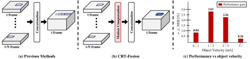
To address these challenges, we propose a motion-aware approach, as illustrated in Figure 1 (b), which goes beyond simple concatenation of BEV feature maps. Our method first estimates the locations of dynamic objects with their corresponding velocity vector for each timestamped BEV feature map. Subsequently, we leverage this predicted information to rectify the motion of dynamic objects in each feature map and fuse them in a temporally consistent manner. Figure 1(c) presents a graph depicting the performance gain achieved by our proposed method over the direct concatenation of temporal BEV feature maps for different object velocity ranges. It is evident that our approach consistently outperforms the existing method across all velocity ranges, with a notable performance improvement for objects moving at medium velocities. This demonstrates the effectiveness of our motion-aware fusion strategy in capturing and compensating for object motion, leading to superior performance in 3D object detection.
In this paper, we introduce CRT-Fusion, a novel approach for integrating temporal information into radar-camera fusion. Our framework comprises three modules: Multi-View Fusion (MVF), Motion Feature Estimator (MFE), and Motion Guided Temporal Fusion (MGTF). The MVF module generates radar-camera fused BEV feature maps for each timestamp. The MVF enhances image features with radar BEV features, achieving more precise depth predictions through Radar-Camera Azimuth Attention (RCA). The enhanced camera BEV features and radar BEV features are integrated through a gating operation. The MFE module predicts velocity information and performs BEV segmentation for each pixel in the fused BEV features to identify object regions and provide values for shifting the feature map spatially. Finally, the MGTF module generates the final feature map by leveraging the fused BEV feature maps, segmentation results, and velocity predictions. The MGTF module begins with the BEV features from the th time step and aligns them with those from each subsequent time step. These aligned features are then aggregated one-by-one across all timestamps in a recurrent manner. Consequently, CRT-Fusion achieves state-of-the-art performance on the nuScenes 3D object detection benchmark for radar-camera fusion methods, with improvements of in NDS and in mAP compared to existing state-of-the-art approaches.
In summary, the main contributions of this work are as follows:
-
•
We introduce CRT-Fusion, a novel framework that effectively integrates temporal information into radar-camera fusion for 3D object detection. By considering the motion of dynamic objects, CRT-Fusion significantly improves detection accuracy and robustness in complex real-world scenarios.
-
•
We design a Multi-View Fusion module that enhances depth prediction by leveraging radar features to improve image features before fusing them into a unified BEV representation.
-
•
We introduce an effective temporal fusion strategy through MFE and MGTF modules. MFE estimates pixel-wise velocity information, and MGTF iteratively aligns and fuses feature maps across multiple timestamps using the motion information obtained from MFE.
-
•
CRT-Fusion achieves state-of-the-art performance on the nuScenes dataset for radar-camera-based 3D object detection, surpassing previous best method by in NDS and in mAP.
2 Related Works
2.1 Camera-Radar 3D Object Detection
Due to the high cost of LiDAR sensors, research on 3D object detection using radar-camera sensor fusion has gained significant traction in recent years. These studies aim to utilize radar sensors as auxiliary sensors to overcome the fundamental limitation of camera-based 3D object detection research, which is the lack of depth information.
CenterFusion [3] adopts a frustum-based approach to establish connections between radar point clouds and image features, enabling the refinement of 3D proposals. CRAFT [1] captures the interactions between radar and camera data within a polar coordinate system using a cross-attention mechanism, effectively integrating information from both modalities. RCM-Fusion [4] combines radar and image features at both feature-level and instance-level to achieve more precise 3D object detection. RADIANT [5] fuses radar and image features within image pixel coordinates to provide more accurate 3D location estimation. CRN [6] employs a 3D object detection method that strikes a balance between speed and performance by leveraging radar information to enhance camera BEV features and fusing multi-modal BEV features. RCBEVDet [2] introduces a novel radar backbone network that utilizes point-based feature extraction techniques for radar and fuses radar and image features using deformable cross-attention. CRKD [7] employs a method to transfer the knowledge possessed by the LiDAR-Camera fusion detector to the Camera-Radar fusion detector using the Cross-modality Knowledge Distillation technique.
2.2 Temporal fusion in 3D Object Detection
The approach to utilizing temporal information in 3D object detection varies depending on the type of sensors employed. In LiDAR-based methods, relying solely on single-frame point cloud data introduces challenges such as occlusion and partial views. To mitigate these issues, several studies have integrated temporal information at the feature level [8, 9, 10, 11]. Another approach involves extracting proposals using an object detector and subsequently leveraging temporal information at the object level [12, 13, 14]. A third method focuses on fusing temporal information within the query representation [15].
On the other hand, camera-based approaches have exploited temporal information to overcome the inherent limitations of image data, such as inaccuracies in depth prediction. One common methodology in camera-based perception research is to fuse temporal information with BEV-based methods [16, 17, 18, 19, 20]. Another approach has centered on enhancing the accuracy of depth estimation through temporal-stereo methods [21, 22, 20].
In the context of radar-camera fusion methods, the utilization of temporal information remains less explored, with most studies following the strategies employed in BEV-based camera-only methods. However, our proposed CRT-Fusion deviates from existing research methods by introducing a novel temporal fusion method. Our approach incorporates a temporal BEV fusion mechanism that explicitly considers the movement of objects, thereby enhancing object detection performance.
3 CRT-Fusion
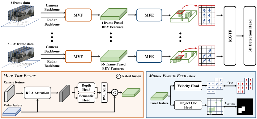
In this work, we introduce CRT-Fusion, a novel framework for 3D object detection that efficiently fuses information from radar, camera, and temporal domains. The overall architecture of CRT-Fusion is illustrated in Figure 2. Our approach first extracts the features from radar and camera data separately using their respective backbone networks. Subsequently, we employ the MVF module to generate a fused BEV feature map for each timestamp by combining the radar and camera features. The sequence of fused feature maps is then utilized by the MFE module to predict the location and velocity information of dynamic objects. The predicted motion information is exploited by the MGTF module to align the BEV feature maps spatially within a time window. Then, the aligned features maps are aggregated to obtain the final feature maps. Finally, 3D object detection is performed using the detection head proposed by CenterPoint [23].
3.1 Multi-View Fusion
Recent advancements in BEV-based camera-only approaches have significantly improved performance, leading to an increased focus on radar-camera fusion approaches within BEV representations. These studies [6, 4, 2] primarily aimed to address the inherent limitations of camera-only approaches, particularly the challenge of accurate depth prediction, by leveraging radar data. The existing state-of-the-art model [6] enhanced this process by combining occupancy information from radar point clouds with camera frustum features, effectively incorporating radar positional data. While this method facilitates the direct integration of radar positional information, noise in radar point clouds can adversely affect depth prediction accuracy. To mitigate this issue, we propose a novel fusion strategy that incorporates radar and camera features in both bird’s eye view and perspective view. Unlike the existing method [6], our approach enhances camera features using radar information prior to depth prediction, enabling more accurate camera BEV features. Subsequently, we employ a CNN-based gated fusion network to obtain the final fused features.
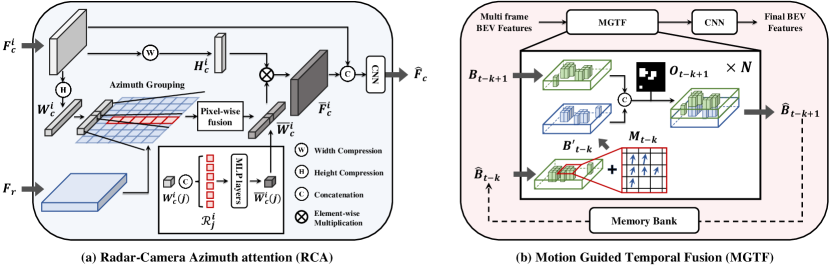
Perspective view fusion. As illustrated in Figure 3 (a), the Radar-Camera Azimuth attention (RCA) module takes the camera perspective view features and the radar BEV features as inputs, where and represent the height and width of the camera features, and and denote the size of the radar BEV features along the x-axis and y-axis, respectively. For the -th image, the camera feature is compressed along both height and width dimensions using max pooling and MLP layers, resulting in and . Let be the value of the features at the -th position along the width direction. We associate the radar feature element at the position with through Azimuth Grouping. The azimuth angle values corresponding to and are denoted as and , respectively. A set of radar features associated with is obtained using
| (1) |
where returns the indices of the smallest elements in , and represents radar features whose azimuth angles are closest to . Pixel-wise fusion module is then applied to to obtain an enhanced feature as
| (2) |
| (3) |
where denotes the -th element of . The concatenation of and is passed through two MLP layers to obtain an intermediate feature . These intermediate features are then processed through another MLP layer followed by a softmax function to determine the relevance to . The weighted sum of these intermediate features yields the enhanced . Finally, we perform an element-wise multiplication of and to obtain the camera perspective view features . The concatenation of and is then passed through a convolution layer to obtain , which is the perspective view features for the -th image fused with the radar BEV features. These steps are depicted in Figure 3 (a).
Bird’s eye view fusion. The enhanced camera feature in the perspective view is employed for depth prediction and camera view semantic segmentation. Inspired by SA-BEV [24], we utilize a 1x1 CNN layer head structure to predict both depth map and segmentation scores in the perspective view. The network outputs , where denotes the number of depth bins and the additional dimension corresponds to the foreground score prediction. The predicted segmentation scores are thresholded using a value to identify the foreground regions only, which are then projected to the BEV domain. The resulting camera BEV features are fused with the radar BEV features obtained from the radar pipeline using a gated fusion network [25, 26] to yield the final BEV features . The gated fusion network assigns weights to each feature according to their significance, effectively boosting the effect of feature fusion.
3.2 Motion Feature Estimation
Temporal fusion methods that consider object motion have been extensively studied in the context of 3D object detection [12, 13, 14]. These methods typically predict object locations and velocities at each timestamp using an object detector, and then aggregate object information from the past timestamps to the current timestamp at the object level. However, this approach has a drawback as the overall model performance heavily depends on the initial detector’s performance. Moreover, object-level temporal fusion methods have not utilized motion information of objects effectively. To address these limitations, we propose a simple yet effective solution: by predicting velocity information and object presence for each pixel in the BEV features, the model can produce the aligned BEV features, which can be temporally fused at the feature level in the BEV domain rather than at the object level.
Suppose that we obtain a set of BEV features from the preceding Multi-View Fusion module, where represents the BEV feature at timestamp . Each feature is then processed in parallel by two distinct heads: a velocity head and an object occupancy head, both composed of 3x3 and 1x1 convolutions. The velocity head extracts motion information , containing velocity estimates along the x and y axes for each pixel in the feature map . Simultaneously, the object occupancy head produces an occupancy score map , where each element indicates whether the corresponding pixel belongs to an object. To facilitate training of these modules, we generate ground truth targets for each timestamp using the following equations. The IoU ratio for a pixel at location is defined as
| (4) |
where is the physical box in the BEV domain corresponding to one pixel located at , is the set of ground truth 3D object boxes, and is the projection of these boxes onto the BEV domain. The IoU ratio calculates the overlap between the physical box and the projected ground truth boxes, helping to determine positive samples. The ground truth values are then given by
| (5) |
| (6) |
where and are the ground truth velocity and occupancy scores for pixel in the BEV feature , respectively. The velocity vector of the corresponding ground truth object is denoted by , and is a predefined threshold set to 0.5. Pixels with an IoU ratio exceeding are classified as positive and assigned the GT velocity and GT occupancy state for supervision.
3.3 Motion-Guided Temporal Fusion
Figure 3 (b) presents the Motion-Guided Temporal Fusion (MGTF) module, which integrates BEV features to construct a dynamic representation of object motion across multiple timestamps. Our model utilizes a memory bank structure, where previously computed BEV features generated through the MGTF process are stored in the buffer, effectively minimizing redundant computations. This memory-efficient design significantly reduces the computational overhead during temporal fusion.
At each timestep , the BEV feature map is retrieved from the memory bank, representing the previous result processed through the MGTF. For each coordinate in , the corresponding velocity vector is used to compute the positional shift and , where denotes the duration of a single frame. These positional shifts are applied to the feature values if the velocity magnitude exceeds a predefined threshold . The shifted feature maps are then obtained as
| (7) |
where
| (8) |
Here denotes the cardinality of and denotes the rounding operation. The shifted feature map is then concatenated with the feature map at the next timestamp. To filter out any irrelevant features resulting from the shifting process, the concatenated feature map is element-wise multiplied with the occupancy score map as
| (9) |
This process is iteratively applied times, generating the BEV feature maps sequentially. The final is then passed through a 1x1 convolution to obtain the final BEV feature map. This sequential nature of the process enhances overall comprehension of the MGTF module.
By incorporating motion information and occupancy score maps, the MGTF module captures the dynamics of moving objects while filtering out irrelevant features, resulting in a more robust BEV representation. Compared to traditional methods, MGTF captures trajectories of moving objects to enhance 3D object detection performance.
4 Experiment
4.1 Experimental setup
Dataset We evaluated our proposed method using the nuScenes dataset [27], a popular public dataset for autonomous driving. This dataset consists of 1,000 scenes, divided into 700 scenes for training, 150 scenes for validation, and 150 scenes for testing. Each scene contains approximately 20 seconds of data. The nuScenes dataset provides comprehensive 360-degree coverage with data from six cameras, and five radars. Keyframes are annotated at a frequency of 2Hz, covering 10 object classes. We use the official evaluation metrics provided by the nuScenes benchmark, which are mean Average Precision (mAP) and nuScenes Detection Score (NDS).
Implementation details We adopted BEVDepth [17] as our baseline model. For a fair comparison with existing methods, we employed ResNet [28], and ConvNeXt [29] as backbone encoders in the camera branch. In the radar branch, we accumulated the past 6 radar sweeps to obtain the input point clouds and used PointPillars [30] with randomly initialized weights as the backbone network. Our proposed CRT-Fusion model performed temporal fusion using the BEV features from the past 6 frames. We also introduce CRT-Fusion-Light, a lightweight version of CRT-Fusion, where the 2D-CNN backbone is removed from the radar pipeline. CRT-Fusion-Light performs temporal fusion using the BEV features from the past 3 frames. Detailed values of hyperparameters including learning rate, optimizer, and data augmentation methods are provided in Appendix.
Method Input Backbone Image Size NDS mAP mATE mASE mAOE mAVE mAAE FPS CenterPoint-P† [23] L Pillars - 59.8 49.4 0.320 0.262 0.377 0.334 0.198 - CenterPoint-V† [23] L Voxel - 65.3 56.9 0.285 0.253 0.323 0.272 0.186 - CenterFusion† [3] C+R DLA34 448800 45.3 33.2 0.649 0.263 0.535 0.540 0.142 - BEVDepth† [17] C R50 256704 47.5 35.1 0.639 0.267 0.479 0.428 0.198 11.6 RCBEV4d† [31] C+R R50 256704 49.7 38.1 0.526 0.272 0.445 0.465 0.185 - CRAFT† [1] C+R DLA34 448800 51.7 41.1 0.494 0.276 0.454 0.486 0.176 4.1 RCM-Fusion† [4] C+R R50 450800 52.8 44.4 0.527 0.272 0.450 0.515 0.180 - SOLOFusion† [20] C R50 256704 53.4 42.7 0.567 0.274 0.411 0.252 0.188 11.4 CRN [6] C+R R50 256704 56.0 49.0 0.487 0.277 0.542 0.344 0.197 20.4 RCBEVDet† [2] C+R R50 256704 56.8 45.3 0.486 0.285 0.404 0.220 0.192 21.3 CRT-Fusion-light† C+R R50 256704 57.8 48.8 0.480 0.265 0.480 0.248 0.189 20.5 CRT-Fusion C+R R50 256704 57.2 50.0 0.499 0.277 0.531 0.261 0.192 14.5 CRT-Fusion† C+R R50 256704 59.7 50.8 0.461 0.264 0.419 0.234 0.186 14.5 MVFusion† [32] C+R R101 9001600 45.5 38.0 0.675 0.258 0.372 0.833 0.196 - BEVFormer [16] C R101 9001600 51.7 41.6 0.673 0.274 0.372 0.394 0.198 1.7 BEVDepth† [17] C R101 5121408 53.5 41.2 0.565 0.266 0.358 0.331 0.190 5.0 SOLOFusion [20] C R101 5121408 54.4 47.2 0.518 0.275 0.604 0.310 0.210 - SOLOFusion† [20] C R101 5121408 58.2 48.3 0.503 0.264 0.381 0.246 0.207 - CRN [6] C+R R101 5121408 59.2 52.5 0.460 0.273 0.443 0.352 0.180 7.2 CRN‡ [6] C+R R101 5121408 60.7 54.5 0.445 0.268 0.425 0.332 0.180 - CRT-Fusion C+R R101 5121408 62.1 55.4 0.425 0.264 0.433 0.237 0.193 4.9
Method Input Backbone NDS mAP mATE mASE mAOE mAVE mAAE PointPillars [30] L Pillars 55.0 40.1 0.392 0.269 0.476 0.270 0.102 CenterPoint [23] L Voxel 67.3 60.3 0.262 0.239 0.361 0.288 0.136 KPConvPillars [33] R Pillars 13.9 4.9 0.823 0.428 0.607 2.081 1.000 RadarDistill [34] R Pillars 43.7 20.5 0.461 0.263 0.525 0.336 0.072 CenterFusion [3] C+R DLA34 44.9 32.6 0.631 0.261 0.516 0.614 0.115 RCBEV [31] C+R Swin-T 48.6 40.6 0.484 0.257 0.587 0.702 0.140 MVFusion [32] C+R V2-99 51.7 45.3 0.569 0.246 0.379 0.781 0.128 CRAFT [1] C+R DLA34 52.3 41.1 0.467 0.268 0.456 0.519 0.114 BEVFormer [16] C V2-99 56.9 48.1 0.582 0.256 0.375 0.378 0.126 BEVDepth [17] C ConvNeXt-B 60.9 52.0 0.445 0.243 0.352 0.347 0.127 SOLOFusion [20] C ConvNeXt-B 61.9 54.0 0.453 0.257 0.376 0.276 0.148 CRN‡ [6] C+R ConvNeXt-B 62.4 57.5 0.416 0.264 0.456 0.365 0.130 SparseBEV [35] C V2-99 63.6 55.6 0.485 0.244 0.332 0.246 0.117 StreamPETR [36] C V2-99 63.6 55.0 0.493 0.241 0.343 0.243 0.123 RCBEVDet [2] C+R V2-99 63.9 55.0 0.390 0.234 0.362 0.259 0.113 CRT-Fusion C+R ConvNeXt-B 64.9 58.3 0.365 0.261 0.405 0.262 0.132 CRT-Fusion‡ C+R ConvNeXt-B 65.6 58.9 0.358 0.258 0.392 0.248 0.130
4.2 Comparison to the state of the art
Table 1 compares our proposed CRT-Fusion method with state-of-the-art 3D object detection methods on the nuScenes validation set. CRT-Fusion consistently outperforms existing radar-camera fusion models and camera-only models across various camera backbone configurations. With the ResNet-50 backbone, CRT-Fusion achieves an improvement of 12.2% in NDS and 15.7% in mAP compared to the baseline model BEVDepth [17]. Additionally, CRT-Fusion achieves 1.2% higher NDS and 1.0% higher mAP than the state-of-the-art model CRN under the same configurations without class-balanced grouping and sampling (CBGS) [37]. Furthermore, when CBGS is applied, our approach outperforms the current best model, RCBEVDet [2] by 2.9% in NDS and 5.5% in mAP. When using the ResNet-101 backbone, CRT-Fusion surpasses CRN by 1.4% in NDS and 0.9% in mAP without test time augmentation (TTA). Our lightweight version, CRT-Fusion-light, maintains a comparable FPS while delivering better performance compared to existing radar-camera 3D object detectors, demonstrating the efficiency and effectiveness of our approach.
4.3 Ablation studies
We conducted comprehensive ablation studies on the nuScenes validation set to evaluate the effectiveness of the key components in CRT-Fusion. Throughout these experiments, unless otherwise specified, we used a ResNet-50 backbone and an image size of 256 704 for the camera branch, and a BEV size of 128 128. All models are trained for 24 epochs without applying CBGS.
Component analysis. To assess the effect of each component, we gradually added each to our baseline model and analyze the performance improvements, as shown in Table 4. The first row shows the performance of the BEVDepth model as reported in the paper, achieving an NDS of 47.5% and an mAP of 35.1%. Our baseline model, represented in the second row, reproduces BEVDepth without CBGS and incorporates long-term temporal fusion [20], achieving an NDS of 47.4% and an mAP of 37.8%. By fusing radar and camera features at the BEV stage, including gating fusion, we observe a significant improvement, reaching an NDS of 55.4% and an mAP of 47.8%. RCA, which fuses radar features in the frustum view, contributes to an additional 1.2% and 1.1% improvement in NDS and mAP, respectively. Finally, by using MFE and MGTF, we achieve an additional gain of 1.1% in both NDS and mAP, resulting in the highest performance with an NDS of 57.2% and an mAP of 50.0%. These results demonstrate the effectiveness of each key component in CRT-Fusion, with our proposed modules providing significant improvements over the baseline model.
Robustness to diverse weather and lighting conditions. In Table 4, we analyze the performance of our model under varying weather and lighting conditions. For a fair comparison, we use the same settings as CRN, with a ResNet-101 backbone and an input size of 512 1408. The baseline model BEVDepth shows low mAP scores due to the impact of weather and light on camera sensors. However, by incorporating radar sensors, which are less affected by these factors, CRT-Fusion achieves over 15% higher mAP in all scenarios. Compared to CRN, the state-of-the-art camera-radar 3D object detection model, CRT-Fusion achieves higher mAP in all conditions except Sunny, offering particularly notable gains in night environments.
Model Configuration Input NDS mAP mATE mAOE BEVDepth [17] C 47.5 35.1 0.639 0.479 Baseline C 47.4 37.8 0.676 0.654 + BEV Fusion C+R 55.4 47.8 0.528 0.584 + RCA C+R 56.1 48.9 0.516 0.574 + MFE & MGTF C+R 57.2 50.0 0.497 0.532
Method MFE & MGTF NDS mAP mAVE BEVDepth X 47.4 37.8 0.312 O 46.9 37.3 0.349 CRT-Fusion X 56.1 48.9 0.278 O 57.2 50.0 0.265
Impact of accurate velocity estimation on MFE and MGTF. Table 6 demonstrates the importance of accurate velocity prediction for each BEV grid. When the MFE and MGTF modules are applied to the camera-based baseline BEVDepth, performance degrades, as shown in the second row of the table. The NDS and mAP scores both drop by 0.5%, highlighting the challenge of accurately estimating velocities solely from camera information. In contrast, CRT-Fusion leverages radar information to achieve more precise velocity predictions. By incorporating the MFE and MGTF modules, CRT-Fusion achieves an improvement of 1.1% in both NDS and mAP, demonstrating the effectiveness of these modules in enhancing the performance. These results indicate that the successful operation of the MFE and MGTF modules is highly dependent on accurate velocity estimation. In the absence of radar data, velocity estimation accuracy is significantly compromised, suggesting that MFE and MGTF modules are optimally suited for radar-camera fusion frameworks.
Comparison of radar-based view transformation methods. Table 6 compares various view transformation methods leveraging radar information. For a fair comparison, we used CRN as the baseline model and conducted experiments in a single-frame setting. The LSS approach predicts 3D depth from camera features and transforms them into BEV features, but can generate inaccuracies due to imprecise depth information. RGVT [39] projects radar points onto the image plane and encodes radar depth features using a lightweight CNN, which are then combined with image features to predict 3D depth. RVT [6] refines the depth distribution predicted from camera features using radar occupancy information. Our proposed RCA outperforms existing methods in almost all metrics, demonstrating its effectiveness in utilizing radar information to transform camera features into accurate BEV features. The superior performance of RCA demonstrates that leveraging radar information for depth prediction significantly enhances BEV perception.
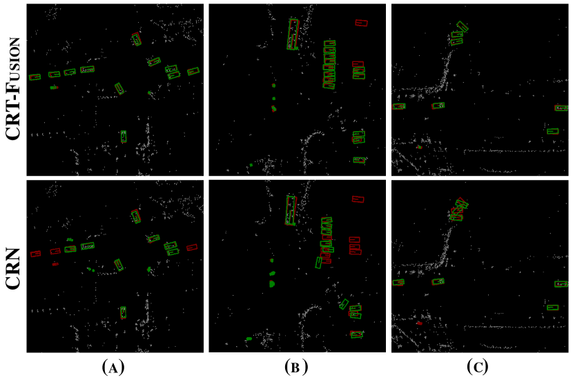
Qualitative results. Figure 4 presents a qualitative comparison between our proposed CRT-Fusion model and the previous state-of-the-art CRN model across various real-world scenarios. CRT-Fusion demonstrates enhanced detection capabilities, accurately identifying objects and showing superior precision in predicting orientations and center positions. Furthermore, CRT-Fusion maintains high accuracy across diverse conditions, effectively capturing multiple targets. These results underscore the robustness and enhanced spatial perception of CRT-Fusion. Additional qualitative results are available in the Supplemental Materials.
5 Discussion and Conclusion
Limitations and future work. While CRT-Fusion achieves significant performance gains over the baseline, the computational cost increases with the number of previous frames used for temporal fusion, limiting the number of frames that can be incorporated due to hardware constraints. This issue is likely due to the parallel fusion structure used for combining BEV features. To address this, a potential solution is to adopt a recurrent fusion structure, which fuses BEV features temporally in a sequential manner. This approach could maintain computational feasibility while incorporating long-term historical BEV features. Future work will explore this recurrent fusion architecture for CRT-Fusion to further reduce its computational complexity.
Conclusion. In this paper, we introduced CRT-Fusion, a novel framework that integrates temporal information into radar-camera fusion for 3D object detection. By explicitly taking the motion of dynamic objects into account through our proposed Motion Feature Estimator and Motion Guided Temporal Fusion modules, CRT-Fusion significantly improves detection accuracy and robustness in complex real-world scenarios. Our Multi-View Fusion module enhances depth prediction by leveraging radar features to improve image features before fusing them into a unified BEV representation. Extensive experiments on the challenging nuScenes dataset demonstrate that CRT-Fusion achieves state-of-the-art performance in the radar-camera-based 3D object detection category, surpassing all existing methods. Additionally, our approach demonstrates remarkable robustness under diverse weather and lighting conditions, highlighting its potential for real-world deployment. We believe that our work will inspire further research on the fusion of temporal and multi-modal information for robust perception in adverse environments.
Acknowledgement
This work was partly supported by the Institute of Information & Communications Technology Planning & Evaluation (IITP) grant funded by the Korea government (MSIT) (No. 2022-0-00957, Distributed on-chip memory-processor model PIM (Processor in Memory) semiconductor technology development for edge applications); the IITP grant funded by the Korea government (MSIT) (No. RS-2021-II211343, Artificial Intelligence Graduate School Program, Seoul National University); and the National Research Foundation of Korea (NRF) grant funded by the Korea government (MSIT) (No. 2020R1A2C2012146).
References
- [1] Youngseok Kim, Sanmin Kim, Jun Won Choi, and Dongsuk Kum. Craft: Camera-radar 3d object detection with spatio-contextual fusion transformer. In Proceedings of the AAAI Conference on Artificial Intelligence, pages 1160–1168, 2023.
- [2] Zhiwei Lin, Zhe Liu, Zhongyu Xia, Xinhao Wang, Yongtao Wang, Shengxiang Qi, Yang Dong, Nan Dong, Le Zhang, and Ce Zhu. Rcbevdet: Radar-camera fusion in bird’s eye view for 3d object detection. arXiv preprint arXiv:2403.16440, 2024.
- [3] Ramin Nabati and Hairong Qi. Centerfusion: Center-based radar and camera fusion for 3d object detection. In Proceedings of the IEEE/CVF Winter Conference on Applications of Computer Vision, pages 1527–1536, 2021.
- [4] Jisong Kim, Minjae Seong, Geonho Bang, Dongsuk Kum, and Jun Won Choi. Rcm-fusion: Radar-camera multi-level fusion for 3d object detection. arXiv preprint arXiv:2307.10249, 2023.
- [5] Yunfei Long, Abhinav Kumar, Daniel Morris, Xiaoming Liu, Marcos Castro, and Punarjay Chakravarty. Radiant: Radar-image association network for 3d object detection. In Proceedings of the AAAI Conference on Artificial Intelligence, pages 1808–1816, 2023.
- [6] Youngseok Kim, Juyeb Shin, Sanmin Kim, In-Jae Lee, Jun Won Choi, and Dongsuk Kum. Crn: Camera radar net for accurate, robust, efficient 3d perception. In Proceedings of the IEEE/CVF International Conference on Computer Vision, pages 17615–17626, 2023.
- [7] Lingjun Zhao, Jingyu Song, and Katherine A Skinner. Crkd: Enhanced camera-radar object detection with cross-modality knowledge distillation. arXiv preprint arXiv:2403.19104, 2024.
- [8] Junho Koh, Junhyung Lee, Youngwoo Lee, Jaekyum Kim, and Jun Won Choi. Mgtanet: Encoding sequential lidar points using long short-term motion-guided temporal attention for 3d object detection. In Proceedings of the AAAI Conference on Artificial Intelligence, pages 1179–1187, 2023.
- [9] Zhenxun Yuan, Xiao Song, Lei Bai, Zhe Wang, and Wanli Ouyang. Temporal-channel transformer for 3d lidar-based video object detection for autonomous driving. IEEE Transactions on Circuits and Systems for Video Technology, 32(4):2068–2078, 2021.
- [10] Zhenyu Zhai, Qiantong Wang, Zongxu Pan, Zhentong Gao, and Wenlong Hu. Muti-frame point cloud feature fusion based on attention mechanisms for 3d object detection. Sensors, 22(19):7473, 2022.
- [11] Rui Huang, Wanyue Zhang, Abhijit Kundu, Caroline Pantofaru, David A Ross, Thomas Funkhouser, and Alireza Fathi. An lstm approach to temporal 3d object detection in lidar point clouds. In Computer Vision–ECCV 2020: 16th European Conference, Glasgow, UK, August 23–28, 2020, Proceedings, Part XVIII 16, pages 266–282, 2020.
- [12] Zetong Yang, Yin Zhou, Zhifeng Chen, and Jiquan Ngiam. 3d-man: 3d multi-frame attention network for object detection. In Proceedings of the IEEE/CVF Conference on Computer Vision and Pattern Recognition, pages 1863–1872, 2021.
- [13] Charles R Qi, Yin Zhou, Mahyar Najibi, Pei Sun, Khoa Vo, Boyang Deng, and Dragomir Anguelov. Offboard 3d object detection from point cloud sequences. In Proceedings of the IEEE/CVF Conference on Computer Vision and Pattern Recognition, pages 6134–6144, 2021.
- [14] Xuesong Chen, Shaoshuai Shi, Benjin Zhu, Ka Chun Cheung, Hang Xu, and Hongsheng Li. Mppnet: Multi-frame feature intertwining with proxy points for 3d temporal object detection. In European Conference on Computer Vision, pages 680–697, 2022.
- [15] Jinghua Hou, Zhe Liu, Zhikang Zou, Xiaoqing Ye, Xiang Bai, et al. Query-based temporal fusion with explicit motion for 3d object detection. Advances in Neural Information Processing Systems, 36, 2024.
- [16] Zhiqi Li, Wenhai Wang, Hongyang Li, Enze Xie, Chonghao Sima, Tong Lu, Yu Qiao, and Jifeng Dai. Bevformer: Learning bird’s-eye-view representation from multi-camera images via spatiotemporal transformers. In European Conference on Computer Vision, pages 1–18, 2022.
- [17] Yinhao Li, Zheng Ge, Guanyi Yu, Jinrong Yang, Zengran Wang, Yukang Shi, Jianjian Sun, and Zeming Li. Bevdepth: Acquisition of reliable depth for multi-view 3d object detection. In Proceedings of the AAAI Conference on Artificial Intelligence, pages 1477–1485, 2023.
- [18] Junjie Huang and Guan Huang. Bevdet4d: Exploit temporal cues in multi-camera 3d object detection. arXiv preprint arXiv:2203.17054, 2022.
- [19] Zhuofan Zong, Dongzhi Jiang, Guanglu Song, Zeyue Xue, Jingyong Su, Hongsheng Li, and Yu Liu. Temporal enhanced training of multi-view 3d object detector via historicalobject prediction. arXiv preprint arXiv:2304.00967, 2023.
- [20] Jinhyung Park, Chenfeng Xu, Shijia Yang, Kurt Keutzer, Kris Kitani, Masayoshi Tomizuka, and Wei Zhan. Time will tell: New outlooks and a baseline for temporal multi-view 3d object detection. arXiv preprint arXiv:2210.02443, 2022.
- [21] Zengran Wang, Chen Min, Zheng Ge, Yinhao Li, Zeming Li, Hongyu Yang, and Di Huang. Sts: Surround-view temporal stereo for multi-view 3d detection. arXiv preprint arXiv:2208.10145, 2022.
- [22] Yinhao Li, Han Bao, Zheng Ge, Jinrong Yang, Jianjian Sun, and Zeming Li. Bevstereo: Enhancing depth estimation in multi-view 3d object detection with dynamic temporal stereo. In Proceedings of the AAAI Conference on Artificial Intelligence, pages 1486–1494, 2023.
- [23] Tianwei Yin, Xingyi Zhou, and Philipp Krahenbuhl. Center-based 3d object detection and tracking. In Proceedings of the IEEE/CVF Conference on Computer Vision and Pattern Recognition, pages 11784–11793, 2021.
- [24] Jinqing Zhang, Yanan Zhang, Qingjie Liu, and Yunhong Wang. Sa-bev: Generating semantic-aware bird’s-eye-view feature for multi-view 3d object detection. In Proceedings of the IEEE/CVF International Conference on Computer Vision, pages 3348–3357, 2023.
- [25] Jaekyum Kim, Junho Koh, Yecheol Kim, Jaehyung Choi, Youngbae Hwang, and Jun Won Choi. Robust deep multi-modal learning based on gated information fusion network. In Asian Conference on Computer Vision, pages 90–106, 2018.
- [26] Jin Hyeok Yoo, Yecheol Kim, Jisong Kim, and Jun Won Choi. 3d-cvf: Generating joint camera and lidar features using cross-view spatial feature fusion for 3d object detection. In Computer Vision–ECCV 2020: 16th European Conference, Glasgow, UK, August 23–28, 2020, Proceedings, Part XXVII 16, pages 720–736, 2020.
- [27] Holger Caesar, Varun Bankiti, Alex H Lang, Sourabh Vora, Venice Erin Liong, Qiang Xu, Anush Krishnan, Yu Pan, Giancarlo Baldan, and Oscar Beijbom. nuscenes: A multimodal dataset for autonomous driving. In Proceedings of the IEEE/CVF Conference on Computer Vision and Pattern Recognition, pages 11621–11631, 2020.
- [28] Kaiming He, Xiangyu Zhang, Shaoqing Ren, and Jian Sun. Deep residual learning for image recognition. In Proceedings of the IEEE Conference on Computer Vision and Pattern Recognition, pages 770–778, 2016.
- [29] Zhuang Liu, Hanzi Mao, Chao-Yuan Wu, Christoph Feichtenhofer, Trevor Darrell, and Saining Xie. A convnet for the 2020s. In Proceedings of the IEEE/CVF Conference on Computer Vision and Pattern Recognition, pages 11976–11986, 2022.
- [30] Alex H Lang, Sourabh Vora, Holger Caesar, Lubing Zhou, Jiong Yang, and Oscar Beijbom. Pointpillars: Fast encoders for object detection from point clouds. In Proceedings of the IEEE/CVF Conference on Computer Vision and Pattern Recognition, pages 12697–12705, 2019.
- [31] Taohua Zhou, Junjie Chen, Yining Shi, Kun Jiang, Mengmeng Yang, and Diange Yang. Bridging the view disparity between radar and camera features for multi-modal fusion 3d object detection. IEEE Transactions on Intelligent Vehicles, 8(2):1523–1535, 2023.
- [32] Zizhang Wu, Guilian Chen, Yuanzhu Gan, Lei Wang, and Jian Pu. Mvfusion: Multi-view 3d object detection with semantic-aligned radar and camera fusion. In 2023 IEEE International Conference on Robotics and Automation (ICRA), pages 2766–2773, 2023.
- [33] Michael Ulrich, Sascha Braun, Daniel Köhler, Daniel Niederlöhner, Florian Faion, Claudius Gläser, and Holger Blume. Improved orientation estimation and detection with hybrid object detection networks for automotive radar. In 2022 IEEE 25th International Conference on Intelligent Transportation Systems (ITSC), pages 111–117, 2022.
- [34] Geonho Bang, Kwangjin Choi, Jisong Kim, Dongsuk Kum, and Jun Won Choi. Radardistill: Boosting radar-based object detection performance via knowledge distillation from lidar features. arXiv preprint arXiv:2403.05061, 2024.
- [35] Haisong Liu, Yao Teng, Tao Lu, Haiguang Wang, and Limin Wang. Sparsebev: High-performance sparse 3d object detection from multi-camera videos. In Proceedings of the IEEE/CVF International Conference on Computer Vision, pages 18580–18590, 2023.
- [36] Shihao Wang, Yingfei Liu, Tiancai Wang, Ying Li, and Xiangyu Zhang. Exploring object-centric temporal modeling for efficient multi-view 3d object detection. In Proceedings of the IEEE/CVF International Conference on Computer Vision, pages 3621–3631, 2023.
- [37] Benjin Zhu, Zhengkai Jiang, Xiangxin Zhou, Zeming Li, and Gang Yu. Class-balanced grouping and sampling for point cloud 3d object detection. arXiv preprint arXiv:1908.09492, 2019.
- [38] Vitor Guizilini, Rares Ambrus, Sudeep Pillai, Allan Raventos, and Adrien Gaidon. 3d packing for self-supervised monocular depth estimation. In Proceedings of the IEEE/CVF Conference on Computer Vision and Pattern Recognition, pages 2485–2494, 2020.
- [39] Zhijian Liu, Haotian Tang, Alexander Amini, Xinyu Yang, Huizi Mao, Daniela L Rus, and Song Han. Bevfusion: Multi-task multi-sensor fusion with unified bird’s-eye view representation. In 2023 IEEE International Conference on Robotics and Automation (ICRA), pages 2774–2781, 2023.
- [40] MMDetection3D Contributors. MMDetection3D: OpenMMLab next-generation platform for general 3D object detection. https://github.com/open-mmlab/mmdetection3d, 2020.
- [41] Junjie Huang, Guan Huang, Zheng Zhu, Yun Ye, and Dalong Du. Bevdet: High-performance multi-camera 3d object detection in bird-eye-view. arXiv preprint arXiv:2112.11790, 2021.
- [42] Zhaoqi Leng, Guowang Li, Chenxi Liu, Ekin Dogus Cubuk, Pei Sun, Tong He, Dragomir Anguelov, and Mingxing Tan. Lidar augment: Searching for scalable 3d lidar data augmentations. In 2023 IEEE International Conference on Robotics and Automation (ICRA), pages 7039–7045, 2023.
- [43] Yan Yan, Yuxing Mao, and Bo Li. Second: Sparsely embedded convolutional detection. Sensors, 18(10):3337, 2018.
Supplementary Materials for CRT-Fusion
In this Supplementary Material, we provide additional details that were not covered in the main paper. We organize the content as follows: comprehensive formulation of loss functions (Section A), architectural specifications and training protocols (Section B), extensive ablation studies and computational efficiency analysis (Section C), in-depth qualitative evaluation on the nuScenes dataset (Section D), and discussion of societal implications (Section E).
Appendix A Loss Function
The total loss function used in CRT-Fusion is composed of five components: a standard 3D object detection loss and four additional losses derived from different head networks within our model. The total loss is given by
| (10) |
where is the 3D object detection loss, is the loss from the Depth Prediction Head in MVF, is the loss from the Perspective-View Semantic Segmentation Head in MVF, is the loss from the Velocity Prediction Head in MFE, and is the loss from the Object Occupancy Prediction Head in MFE. The parameters , , , and are the weights for the corresponding loss terms. The Depth Prediction Loss uses binary cross-entropy loss for depth estimation, with a weight of , following the approach used in BEVDepth. For the Perspective View Segmentation Loss, we also employ the binary cross-entropy loss, with a weight of , inspired by SA-BEV. The Velocity Prediction Loss, which handles velocity and orientation prediction, utilizes Mean Squared Error (MSE) with a weight of . Finally, the BEV Object Occupancy Loss uses Binary Focal Loss for foreground and background segmentation, with a weight of .
Appendix B Implementation Details
The nuScenes datasets [27] are publicly available to use under CC BY-NC-SA 4.0 license and can be downloaded from https://www.nuscenes.org/. We implemented our model using the MMDetection3D [40] codebase and trained it for a total of 24 epochs. The training process consists of two phases. In the initial phase, the model is trained for 6 epochs without the MGTF module. Then, the entire model is trained for the remaining 18 epochs. For the ResNet50-based model, we used 4 NVIDIA RTX 3090 GPUs for training, while for ResNet101 and ConvNeXt-B, we used 3 NVIDIA A100 GPUs. Table 7 summarizes the training settings for different camera backbone networks.
In the perspective view, we apply data augmentation techniques consistent with previous studies [41, 17, 6], including horizontal random flipping, random scaling , and random rotation . For the bird’s-eye view, we employ random flipping along the x and y axes, random scaling , and random rotation . Additionally, we use a technique that randomly drops radar sweeps and points [42]. To ensure a fair comparison with other models, we do not utilize ground-truth sampling augmentation (GT-AUG) [43], which is commonly used in LiDAR-based models.
| Configs | ResNet-50 | ResNet-101 | ConvNext-B |
| Image size | |||
| BEV size | |||
| Optimizer | AdamW | AdamW | AdamW |
| Base Learning Rate | 2e-4 | 1e-4 | 1e-4 |
| Weight Decay | 1e-7 | 1e-7 | 1e-2 |
| Optimizer Momentum | 0.9, 0.999 | 0.9, 0.999 | 0.9, 0.999 |
| Batch Size | 16 | 12 | 12 |
| Training Epochs | 24 | 24 | 24 |
| LR Schedule | Step Decay | Step Decay | Step Decay |
| Gradient Clip | 5 | 5 | 5 |
Appendix C Additional Experimental Results
C.1 Analysis of the Motion Feature Estimation Module.
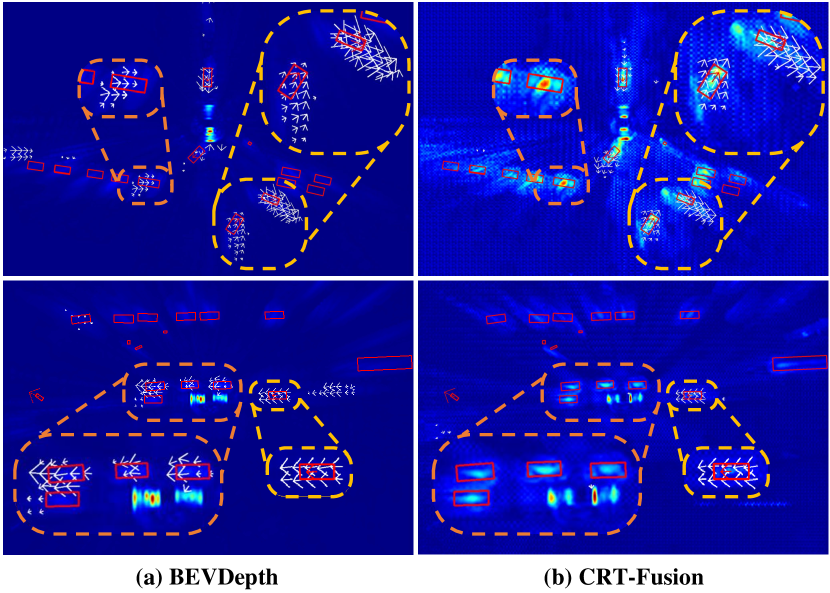
The Motion Feature Estimation (MFE) module generates a motion-aware BEV feature map by estimating velocity for each grid and using it to refine the BEV representation. While MFE can be integrated into various architectures, its effectiveness is highly reliant on accurate velocity predictions. To demonstrate this, we applied MFE to both the camera-based model BEVDepth and our proposed CRT-Fusion, which incorporates radar data.
Figure 5 shows the results of applying the MFE module to each model. The red boxes represent Ground Truth (GT) boxes, the red arrows indicate GT velocity, and the white arrows show the predicted velocity from the MFE module. The size and direction of the arrows reflect the velocity’s magnitude and direction. The yellow and orange highlights illustrate the differences in velocity prediction accuracy and the ability to distinguish static objects. Specifically, in the yellow-highlighted areas, CRT-Fusion predicts velocities closely aligned with GT, whereas BEVDepth shows inaccuracies. In the orange-highlighted areas, CRT-Fusion accurately identifies static objects, while BEVDepth misclassifies them as dynamic. In conclusion, the effectiveness of the MFE module is closely tied to the accuracy of velocity estimation. Integrating radar data in CRT-Fusion significantly enhances the module’s ability to generate reliable motion-aware BEV features, underscoring the value of sensor fusion for robust 3D object detection.
# of prev frames NDS mAP mATE mAOE mAVE 0 50.4 44.4 0.515 0.598 0.567 1 55.1 47.1 0.508 0.570 0.295 2 56.0 48.1 0.506 0.542 0.280 3 56.6 48.8 0.498 0.540 0.269 4 56.7 49.3 0.505 0.556 0.268 5 56.6 49.2 0.506 0.557 0.262 6 57.2 50.0 0.494 0.557 0.265 7 57.3 49.8 0.497 0.532 0.265 8 57.3 49.7 0.499 0.531 0.261
| NDS | mAP | |
| 0.15 | 56.8 | 49.4 |
| 0.20 | 56.6 | 49.0 |
| 0.25 | 57.2 | 50.0 |
| 0.30 | 56.7 | 49.4 |
| NDS | mAP | |
| 0.00 | 56.7 | 49.2 |
| 0.05 | 57.2 | 50.0 |
| 0.10 | 56.0 | 48.7 |
| 0.15 | 55.8 | 48.4 |
| NDS | mAP | |
| 0.0 | 57.0 | 49.2 |
| 0.5 | 56.6 | 48.9 |
| 1.0 | 57.2 | 50.0 |
| 1.5 | 56.8 | 49.3 |
| # of grid | NDS | mAP |
| 32 | 56.1 | 48.8 |
| 64 | 56.8 | 49.3 |
| 128 | 57.2 | 50.0 |
| 256 | 56.7 | 49.4 |
C.2 Hyperparameter Analysis.
The ablation studies on the hyperparameters used in CRT-Fusion are shown in Tables 8 and 9. Table 8 examines the optimal number of previous frames to consider for achieving the best performance. The results show that the performance of CRT-Fusion improves as the number of frames increases, with 6 frames yielding the best results when considering computational cost and performance. Tables 9 (a) and (b) investigate the optimal segmentation thresholds for the perspective view and bird’s eye view (BEV), respectively. In the perspective view, a segmentation threshold of 0.25 achieves the best performance, while in the BEV, a threshold of 0.05 yields the highest performance. Increasing the threshold may lead to the removal of foreground regions, resulting in a decline in performance. Table 9 (c) explores the velocity threshold for considering a BEV grid as a dynamic object in the MFE module. The results demonstrate that considering BEV grids with velocities above 1 m/s achieves the highest performance. Finally, Table 9 (d) examines the number of radar BEV grids to match with each image feature pixel in the RCA module. The experiments reveal that matching 128 grids yields the best performance.
C.3 Evaluating Model Efficiency.
Table 10 presents the analysis of performance, latency, and GPU memory usage of CRT-Fusion and CRN as the number of past frames increases. We reproduced the CRN model following the official implementation. For a fair comparison, both models employ identical camera and radar backbones with consistent input image dimensions. All experimental evaluations were conducted on a single NVIDIA RTX 3090 GPU and an Intel Xeon Silver 4210R CPU.
Our experimental results demonstrate that CRT-Fusion consistently achieves superior performance in both NDS and mAP metrics across all temporal configurations. Notably, as we extend the temporal context by incorporating additional past frames, CRT-Fusion exhibits stable resource usage with minimal degradation. The memory efficiency of our approach is evidenced by its peak consumption of 3.754 GB at 7 frames, while CRN reaches 4.342 GB under identical conditions. In terms of computational latency, CRT-Fusion demonstrates robust scalability, with inference time increasing moderately from 57.1 ms to 69.6 ms when expanding from 0 to 7 frames. CRN also benefits from increased temporal information, although it experiences a more substantial increase in computational overhead, with latency reaching 273 ms at 7 frames. These empirical results highlight the efficiency of our proposed architecture in maintaining real-time inference capabilities while utilizing temporal information effectively.
# of prev frames CRT-Fusion CRN NDS mAP Mem (GB) Latency (ms) NDS mAP Mem (GB) Latency (ms) 0 50.35 44.37 3.686 57.1 44.24 41.36 4.232 55.6 1 55.08 47.07 3.692 62.0 53.14 43.80 4.244 85.0 2 56.03 48.07 3.698 62.8 54.79 45.88 4.270 120.2 3 56.60 48.82 3.706 64.2 55.57 46.87 4.286 138.6 4 56.66 49.29 3.714 64.9 56.01 47.10 4.302 187.1 5 56.55 49.19 3.724 66.2 55.83 47.18 4.310 212.0 6 57.15 50.01 3.744 67.1 55.55 47.40 4.326 243.5 7 57.30 49.75 3.754 69.6 56.30 47.61 4.342 273.0
C.4 Latency Analysis of CRT-Fusion and CRT-Fusion-light.
Table 11 presents the component-wise latency analysis of our CRT-Fusion variants. CRT-Fusion-light, which incorporates a lightweight radar backbone and processes fewer temporal frames, achieves an overall latency of 48.8 ms compared to 67.1 ms of the original architecture. The efficiency gains primarily originate from the radar processing pipeline, where the radar backbone latency decreases from 13.9 ms to 3.9 ms, and the MGTF module reduces from 15.2 ms to 8.6 ms.
Methods C.B. R.B. MVF MFE MGTF Head Total CRT-Fusion 13.4 ms 13.9 ms 15.0 ms 0.7 ms 15.2 ms 8.9 ms 67.1 ms CRT-Fusion-light 13.4 ms 3.9 ms 13.3 ms 0.7 ms 8.6 ms 8.9 ms 48.8 ms
Appendix D Qualitative results of CRT-Fusion.
Figure 6 showcases qualitative results of our proposed CRT-Fusion method on the nuScenes validation set. We compare the object detection performance of CRT-Fusion with the baseline model, BEVDepth, by visualizing the predicted bounding boxes in the BEV representation. Both models employ a ResNet-101 as the camera backbone for feature extraction. The examples demonstrate the effectiveness of CRT-Fusion in various driving scenarios, such as urban streets, intersections, and highways. Our model consistently produces more accurate and well-aligned bounding boxes compared to the baseline model.
Appendix E Discussions of potential societal impacts.
CRT-Fusion has the potential to enhance the accuracy and robustness of 3D object detection in autonomous vehicles and robotics systems by fusing radar, camera, and temporal information. Despite its benefits, the reliance on sophisticated technology and data fusion could lead to increased costs and complexity, potentially limiting accessibility and widespread adoption.