[1]\fnmM. \surStern
1] \orgdivQuantum Nanoelectronics Laboratory, \orgnameDepartment of Physics & Bar-Ilan Institute of Nanotechnology and Advanced Materials (BINA), \orgaddress\cityRamat-Gan, \postcode5290002, \countryIsrael
2]\orgdivARC Centre for Quantum Computation and Communication Technology (CQC-T) & School of Physics, \orgnameUniversity of Melbourne, \orgaddress \cityParkville, \postcode3010, \stateVIC, \countryAustralia 3]\orgdivSchool of Science, \orgnameRMIT University, \orgaddress\cityMelbourne, \postcode3000, \stateVictoria, \countryAustralia
Strong coupling of a superconducting flux qubit to single bismuth donors
Abstract
The realization of a quantum computer represents a tremendous scientific and technological challenge due to the extreme fragility of quantum information. The physical support of information, namely the quantum bit or qubit, must at the same time be strongly coupled to other qubits by gates to compute information, and well decoupled from its environment to keep its quantum behavior. An interesting physical system for realizing such qubits are magnetic impurities in semiconductors, such as bismuth donors in silicon. Indeed, spins associated to bismuth donors can reach an extremely long coherence time - of the order of seconds. Yet it is extremely difficult to establish and control efficient gates between these spins. Here we demonstrate a protocol where single bismuth donors can coherently transfer their quantum information to a superconducting flux qubit, which acts as a mediator or quantum bus. This superconducting device allows to connect distant spins on-demand with little impact on their coherent behavior.
Spins in semiconductors are often considered as one of the major candidates for quantum information processing [1, 2]. They can be extremely well isolated from their environment by choosing a proper ultrapure surrounding lattice, that contains only nuclei with zero spin. Consequently, they can safely store quantum information with low error rates [3]. The primary obstacle in developing a spin-based quantum processor is the realization of gates between distant individual spins [4, 5, 6]. Indeed, quantum computation requires in addition to single qubit gates, a two qubit controlled rotation which rotates the spin of a target qubit if and only if the control qubit is oriented in a given direction. For impurity donors, one possible approach consists of directly coupling adjacent spins by electrically controlling their exchange interaction [7]. Although this method can potentially yield coupling strengths on the order of GHz [8], it requires positioning the donor atoms less than apart. This proximity requirement presents substantial challenges for the fabrication of the ancillary structures needed for control and readout of the qubit register.
Indirect coupling strategies involve using a common intermediate element such as a superconducting resonator to couple distant spins at long distances [9, 10, 11]. The magnetic coupling strength of a single electron spin to a superconducting resonator is however extremely small. It can be estimated from the amplitude of the magnetic field fluctuations, , generated by the circuit. Assuming an infinitely thin wire, the field fluctuations are given by Biot and Savart law as where are the current fluctuations in the wire, is the distance from the wire to the spin, the characteristic impedance of the resonator and its resonance frequency [12]. Assuming the electron behaves as a point-like particle and the magnetic field is oriented in a direction perpendicular to the spin axis, the magnetic coupling is given by where is the electron gyro-magnetic ratio, is a Pauli operator acting on the spin degree of freedom and and are respectively the annihilation and creation operators of an excitation (photon) in the resonator. We thus obtain the coupling constant,
| (1) |
A microwave resonator with resonance frequency in the and designed with a low impedance [13] exhibits current fluctuations comprised between , which give rise to a coupling constant of only for a spin situated at a distance of approximately from the circuit.
One solution to overcome this weak coupling consists of translating the spin degree of freedom into an electrical dipole. Indeed, the coupling strength of an electrical dipole to a microwave resonator may be orders of magnitude larger than for a magnetic dipole. In 2015, Viennot et al. [14] used this method to translate an electron spin in a carbon nanotube into an electrical dipole, by the application of a local magnetic gradient, reaching the strong coupling regime. Along these lines, Petta and coworkers have demonstrated the strong coupling between a silicon double quantum dot and a microwave coplanar waveguide resonator [15]. In a follow-up experiment, they added a cobalt micro-magnet to transfer the spin degree of freedom to the position of the electron in the double quantum dot [16]. A spin–photon coupling rates of up to was reported and the strong coupling was achieved. However, due to the presence of charge noise, the spin decoherence rate was severely degraded to a few megahertz.
Clearly, using an electrical degree of freedom is a good solution for reaching the strong coupling regime between a nano-object and a microwave resonator. However, the same electrical degree of freedom makes this nano-object sensitive to electrical noise which implies a severe degradation of its coherence properties. A spin is intrinsically immune to charge noise, but its magnetic coupling to a circuit is small and thus requires large current quantum fluctuations (see Eq. 1).
In this work, we couple spins to a highly non-linear circuit with huge current quantum fluctuations [17, 18, 19]. This circuit - called a superconducting flux qubit - consists of a superconducting loop intersected by four Josephson junctions, among which one is smaller than the others by a factor . It behaves as a two-level system when the flux threading the loop is close to half a flux quantum [20, 21, 22]. Each level is characterized by the direction of a macroscopic persistent current flowing in the loop of the qubit. The value of the persistent current , typically of the order of , gives rise to a huge magnetic moment , making the energy of each level extremely sensitive to external magnetic flux. At , the two levels are degenerate, hybridize and give rise to an energy splitting called the flux-qubit gap, accompanied with large current fluctuations . Close to , the effective Hamiltonian of the circuit can be written as
| (2) |
where , and are Pauli operators acting on the subspace formed by the ground and first excited eigenstates of the circuit Hamiltonian. The two major issues with flux qubit designs are device-to-device gap reproducibility and coherence [23, 24, 25, 26, 27]. These problems have been recently solved by new fabrication techniques allowing an extremely good control of e-beam lithography, oxidation parameters of the junctions and sample surface treatment [28].
The second parameter to optimize the magnetic coupling is the distance between the spin and the circuit (see Eq. 1). The spin species should be chosen carefully to allow this precise positioning. Here, bismuth donors in silicon (Si:Bi) are chosen since they can be implanted near the surface with good yield and low straggling [29] and possess long coherence times [30, 31]. The bismuth donor has a nuclear spin and an electron spin . The Hamiltonian of a single bismuth donor in silicon can be written as follows
| (3) |
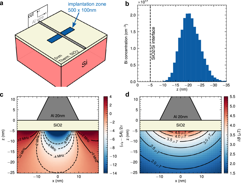
The first two terms in the Hamiltonian are respectively the Zeeman electronic and nuclear terms, being the nuclear gyro-magnetic ratio. The last term is the hyperfine coupling term () and is isotropic due to the symmetry of the donor. One of the advantages of bismuth donors is their large hyperfine coupling constant, which gives rise to an electron spin resonance transition at without application of an external magnetic field [32, 33, 34]. As we will see in the following, this is very convenient for resonantly coupling such a spin to a superconducting flux qubit. In this work, the Si:Bi donors are positioned at a depth of approximately below the surface in regions of implantation of . Each region contains a total of approximately active electron spins (following Poisson statistics).
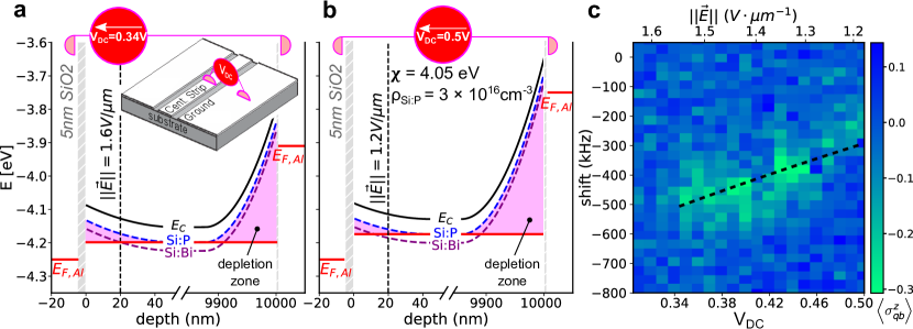
Aluminum deposited directly on top of a native silicon substrate gives rise to a Schottky barrier in which the bismuth donors may be ionized [33]. Indeed, aluminum has a higher work function than the electron affinity in silicon . Bismuth is a shallow donor situated at below the conduction band. Thus, an electron occupying the donor site is situated at a higher electro-chemical potential than the Fermi level of the aluminum, leading to spontaneous ionization of the donors in the so-called depletion zone. A well-known solution to this problem consists of introducing a thin insulating layer of silicon oxide () in order to prevent the exchange of electrons between the substrate and the aluminum. Consequently, our sample is fabricated on a thermally grown silicon oxide layer [28]. By applying a positive voltage on the top electrode, it is possible to be assured that the donors cannot be ionized. Inversely, the donors become ionized below a specific voltage threshold.
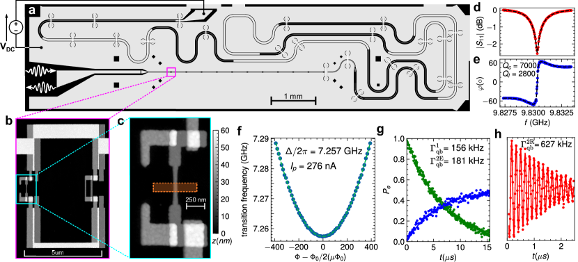
In Fig. 1a, we present a coplanar waveguide resonator design which allows the application of this DC voltage. To achieve this goal, the resonator is terminated on the left by a capacitor and on the right by a Bragg filter (see Methods). The voltage bias is applied directly on the Bragg filter port between the central strip and the ground plane. A positive voltage should be maintained during the cool-down, such that the donors below the central conductor will retain their electrons (see Extended Data Fig. 5). A series of eleven flux qubits is connected galvanically to the central conductor of the resonator. In Fig. 1b, we present an Atomic Force Microscope (AFM) micrograph of one of these qubits. It contains a thin constriction of aluminum () that crosses an implantation region as shown in Fig.1c.
We now present experiments on the spectroscopic measurements for characterization of the qubit-resonator system (See Methods for more details on the experimental setup). In Fig 1d-e, we present the amplitude and phase of the reflected signal on the capacitor port. One can extract from these measurements the frequency of the resonator and its quality factor . In Fig. 1f, we present the spectroscopy of the flux qubit which will be used in the following experiment to detect and couple Si:Bi spins. One can extract from this measurement the qubit gap and its persistent current . We now turn to the coherence times at the so-called optimal point where the qubit frequency is minimal and thus insensitive to flux-noise to first order [23, 24, 28]. Energy relaxation decay is shown in Fig. 1g from which we extract . This decay rate is considerably higher than what was obtained in Ref. [28] and may be due to higher dielectric losses in the substrate due to the presence of residual dopants or to a bad interface between the epilayer and the substrate. Ramsey fringes show an exponential decay with and pure dephasing rate . The spin-echo decays exponentially with a pure echo dephasing rate of . Away from the optimal point the pure dephasing rate becomes dominated by 1/f flux noise and increases proportionally with , giving access to the amplitude of flux noise [28]. This value is significantly higher than typical flux noise amplitudes for qubits fabricated with the same technique and measured under similar conditions [28] and again may be related to the presence of residual dopants in the substrate.
Clearly, working at the flux qubit optimal point is required if one wishes to have a flux qubit with good coherence properties. It is therefore important to engineer the flux qubit gap to be resonant with the spins if one wishes to make a coherent exchange. In this work, we achieve this condition by applying a resonant Rabi drive on the flux qubit biased at its optimal point [35]. The driven Hamiltonian is written as
| (4) |
Even if the coupling constant is several orders of magnitude smaller than the detuning , one can show that this Hamiltonian is equivalent to a time-independent flip-flop Hamiltonian when the condition is satisfied (for more details see Methods). The advantage of this coupling scheme is that one can turn on and off the coupling by controlling the amplitude of the microwave tone.
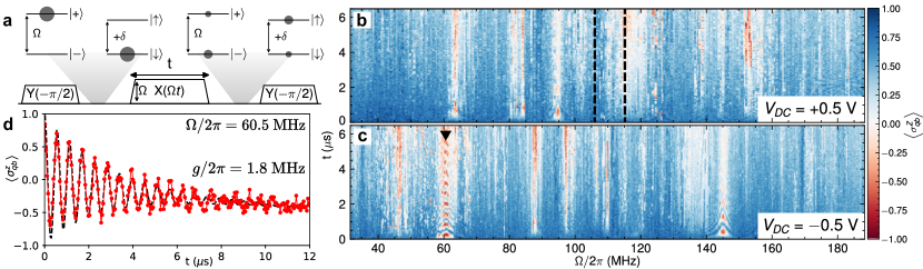
In Fig. 2a, we present a protocol to detect the presence of impurity donors or more generally any two-level systems (TLS) in the vicinity of the flux qubit. A first pulse operates a rotation of around the Y axis of the Bloch sphere and transfers the qubit initialized in its ground state to the state. This state being an eigenstate of should remain unchanged in the presence of a second pulse along the X axis of amplitude and frequency . The third pulse operates a rotation of around the Y axis and brings the qubit to its excited state, . The presence of an impurity donor or TLS modifies this picture when [36]. In that case, the qubit can exchange its excitation during the application of the second pulse with a spin or TLS initially in its ground state . Consequently, the flux qubit state does not reach after the third pulse is applied.
Fig. 2b, shows a color plot representing the flux qubit state at the end of the sequence versus the second pulse amplitude and duration. A change in the color is observed when the qubit can efficiently exchange energy with a surrounding TLS. The measured spectrum unveils that a large number of TLSs interacts with the qubit. This spectrum may vary as a function of time on a typical timescale hours or days. Some rare events affect several TLSs together with frequency jumps that can reach tens of megahertz. The spectrum can also be modified by changing the gate voltage as shown in Fig. 2c. If the TLS is an impurity donor in the silicon wafer, it should be ionized when a negative voltage is applied. Some TLSs are strongly coupled to the qubit and can exhibit coherent exchange (see Fig. 2d) but most of them have a rather short relaxation time.
In the following, we will use this short relaxation time as a way to filter the signal coming from the Si:Bi donors. Indeed, the relaxation time of donors in silicon can be extremely long at low temperatures. In Ref. [37], the relaxation time of a single phosphorous donor was measured to be . In Ref. [34] non-radiative energy relaxation of an ensemble of bismuth donors was measured to be even longer, reaching approximately at dilution temperatures .
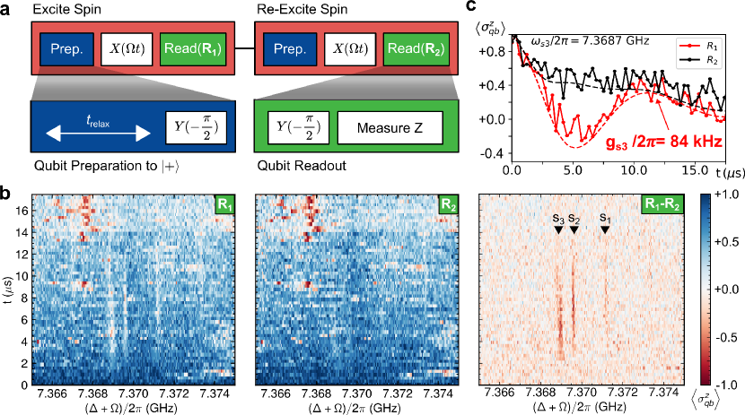
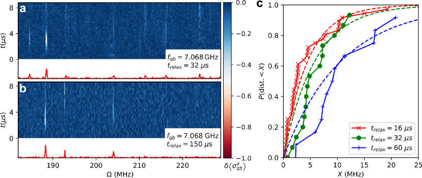
In Fig. 3a-b, we apply twice the protocol described in Fig. 2a and represent the difference between the measurement after the first and second pulse sequences. Thus, only species with a relaxation time longer than the duration of the sequence will appear. In our range of interest, three lines can still be observed. We measure signals at , , , which disappear under a negative voltage bias.
As mentioned earlier, most random TLSs have a rather short relaxation time in the few microsecond range [38, 39]. However, some rare TLSs may exhibit longer relaxation times [40]. To address this concern, we performed a statistical analysis of detectable TLSs (see Extended Data Fig. 4). For a time , the spectral density of these long-lived TLSs is around . As we increase ( or ), the spectral density of TLSs decreases to or respectively. At , the TLSs become very rare with a spectral density of .
With approximately 60 activated spins intentionally introduced in the implantation region, we expect to find around 3 spins beneath the aluminum constriction. The probability to detect three random TLSs with long relaxation time in a range of 4 MHz exists but is very low (less than ). Additionally, the behavior of the detected spectral line under the application of an electric field (see Extended Data Fig. 5) is in excellent agreement with the expected Stark shift of bismuth donors [41].
The frequencies of the detected signals are close to the zero field splitting of bismuth donors in bulk silicon (7.377 GHz) but slightly shifted. The shift of the spectral lines is due to the close proximity of the aluminum wire, which generates mechanical stress resulting from the mismatch of the coefficient of thermal expansion between the substrate and the metal. This stress induces a shift in the hyperfine coupling strength that has been experimentally measured [42, 43]. To first approximation, one may introduce modifications to the constant depending on diagonal terms only of the strain tensor . Namely,
| (5) |
with [43]. Using the simulation of Extended Data Fig. 2c, we see that these frequency shifts are compatible with bismuth donors lying in the close vicinity of the constriction and we can infer their approximate distance to the circuit.
In Fig. 3c, we present the expectation value as a function of interaction time between one of the donors (spin s3) and the resonantly driven qubit. Coherent exchange between the driven flux qubit and the bismuth electron spin is observed. This measurement enables us to extract the coupling between the qubit and the spin, as was done previously in Fig. 2c for an arbitrary TLS. We repeat this measurement for the three single donors and find their respective coupling constants with the qubit, namely , and . These values are in good agreement with what is expected from a simple Biot and Savart simulation (see Extended Data Fig. 2d.), assuming that spins are point-like particles.
A first application of the coupling described herein above consists of quickly initializing the spins, without waiting for their long relaxation time. Preparing the state of the flux qubit in (or ) and letting the system evolve for will set the spin to state (or respectively), independently of the initial spin state. In our experiments, the purity of the spin state is affected by the flux qubit decoherence during the interaction time. One way to improve the preparation of the target state ( or) consists of repeating the protocol typically two to five times [35]. The repetition of the protocol improves the state initialization until it reaches an asymptotic value.
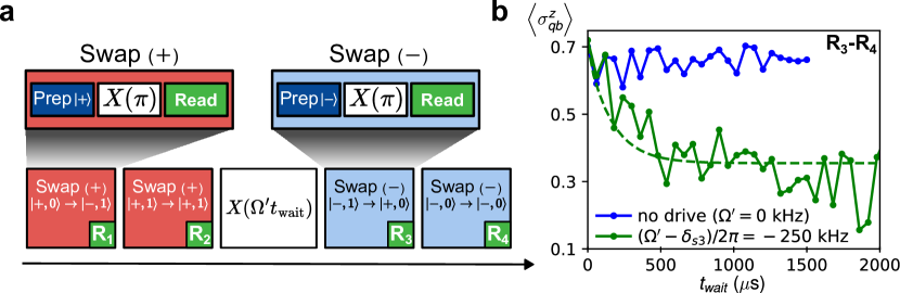
Once its state is well initialized, the spin can serve as a quantum memory for the flux qubit. In Fig. 4a-b, we present the simplest case illustrating a possible use of this memory. Here, the spin is first initialized in . After a waiting time , its state is mapped back to the qubit by letting the system evolve for with a qubit prepared initially in state. This measurement should enable us to extract information about the relaxation time of the spin. This time is very long, much larger than the millisecond scale on which our measurement is done. In order to increase the relaxation rate of the spin to some reasonable values, one can drive the qubit out of resonance during the waiting time in order to open a relaxation channel by Purcell effect via the qubit [34]. For instance, the relaxation rate of the spin is increased to when the qubit is detuned from the spin by .
The fidelity of the quantum memory protocol can be increased by having a qubit with longer relaxation and dephasing times. We suspect that the relatively short relaxation time of our qubit is related to the presence of residual dopants or a to bad interface between the isotopically purified epilayer and the substrate. In future experiments, we will rather use a different technique where isotopically enriched regions can be directly formed on an intrinsic high resistivity sample. This technique allows for local isotopic enrichment through sputtering and implanting of a high fluence of ions [44]. Another important parameter to improve in further experiments is the stability of the drive power, which currently represents an intrinsic limitation of our experimental technique. Indeed, a typical microwave power stability of 0.2% will give rise to variations of the Rabi frequency of , which is an issue for obtaining a good coherent exchange. One possible way to solve this question consists of using a double drive scheme where the flux qubit is driven simultaneously along two axes. This kind of technique has been already demonstrated for stabilizing Rabi oscillations [45]. It could be possible to exploit it further in order to establish an effective coupling between two spins, using the qubit as a mediator.
1 Methods
1.1 Experimental Setup
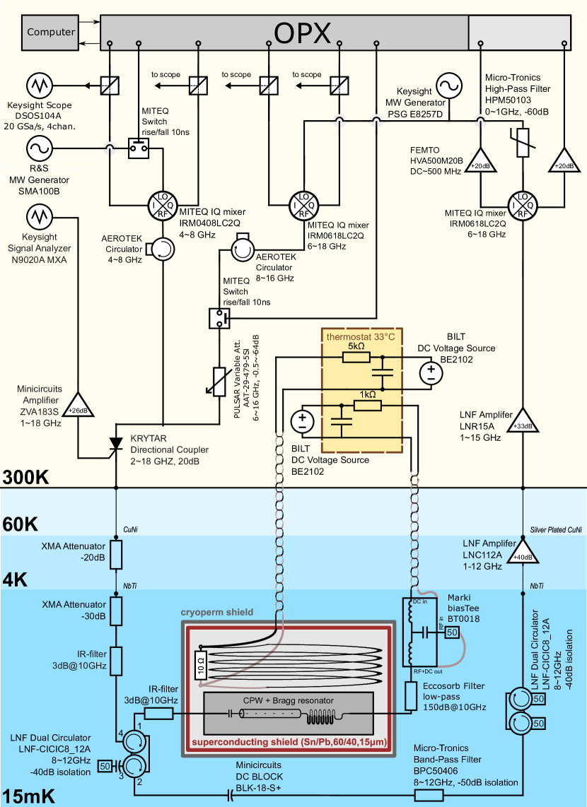
Experiments are performed at a temperature of in a dilution refrigerator. Extended Data Fig. 1 shows a detailed schematic of the experimental setup. The sample is glued on a microwave printed circuit board made out of TMM10 ceramics, then enclosed in a copper box with low mode volume which is itself embedded into a superconducting coil that is used to provide magnetic flux biases to the qubits. To reduce low frequency magnetic noise, the coil is surrounded by a superconducting enclosure and magnetically shielded with a high permeability metal box. The apertures of the box are tightly closed using microwave absorber, in order to protect the sample from electromagnetic radiation that could generate quasiparticles.
The coil is powered by a voltage source filtered by a custom designed ultra-stable voltage to current converter. The microwaves are generated by ultra-low noise analog microwave synthesizers. The pulses are modulated at an intermediate frequency of by a Quantum Machines OPX system connected to IQ mixers. Voltage controlled attenuator is used to adjust the measurement pulse amplitude. The input line is attenuated at 4K stage (-20 dB) and at the mixing chamber stage (-30 dB)to minimize thermal noise and filtered with homemade impedance-matched copper powder filters (-3 dB @ ). In addition, the pulses are shaped with smooth rise and fall ( ns) in order to reduce the population of microwave photons in the resonator during coherent state evolution of the qubit. A DC voltage () is applied on the Bragg filter port of the resonator using a bias tee thermalized at . Additionally, the input noise on this port is strongly filtered by an homemade Eccosorb low-pass filter (-150 dB @ ).
Qubit state measurement is done using dispersive readout, by measuring the reflection of microwave pulses on the capacitor port of the resonator, using a custom built setup. The readout output line is filtered by two shielded double circulators and a band pass filter. The readout output signal is amplified using a low-noise cryogenic HEMT amplifier and a room temperature amplifier. After demodulation, the quadratures of the readout output pulse are sampled and averaged using the IQ inputs of the OPX system. At this point, we perform a principal axis transformation on the data points by diagonalizing their covariance matrix. Using this transformation, we extract the largest principal component of the measured points and obtain the state of the qubit.
1.2 Sample design and fabrication
The sample is fabricated on a thick wafer of natural silicon covered by a isotopically enriched epilayer containing 730 ppm of residual and background doping of approximately phosphorus donors. Before implantation, the sample is covered by a thermally grown width layer. This gate oxide step is followed by a forming gas annealing to passivate dangling bounds at the interface.
1.2.1 Bismuth donors implantation
The Si:Bi donors are located in regions of size which are defined by e-beam lithography using a polymethyl methacrylate (PMMA) mask (). The Si:Bi donors are positioned at a depth of approximately below the surface by ion implantation with an energy of 26 keV (see SRIM simulation in Extended Data Fig. 2). The implantation area density is , which translates into a peak density of bismuth impurities of . The implantation is followed by a cleaning step to remove the PMMA mask and a rapid thermal annealing (, Ar, ) to activate the bismuth donors. Taking into account an activation ratio of 60% [29], a total of approximately 60 electron spins are present in each implantation region. Dangling bounds at the interface are passivated with an evaporation of a aluminum layer followed by a forming gas annealing (. This aluminum layer acts as a catalyst for atomic hydrogen which efficiently passivates the interface states. Then, the sample is etched by aluminum etchant and cleaned.
1.2.2 Coplanar waveguide resonator fabrication
After one night of pumping, we evaporate a clean layer of aluminum onto the chip. Optical resist (AZ1505) is spun on the sample and a coplanar waveguide resonator is patterned by UV laser lithography. This resonator is terminated on the left side by a capacitor and on the right side by a Bragg filter. The value of the capacitance is calculated by an electromagnetic simulator (Sonnet) to be . The Bragg filter is formed by eleven layers of identical length with alternate characteristic impedance and . This change of characteristic impedance is obtained by changing the width of the central conductor and its spacing to the ground. The Bragg filter is designed to have a band gap centered around with a bandwidth at -3 dB of +/- , in order to protect the qubits from relaxation via the line. After development, the wafer is etched with aluminum etchant, followed by cleaning in N-Methylpyrrolidone (NMP) overnight.
1.2.3 Flux qubit fabrication
The flux qubits are fabricated by e-beam lithography using the so-called Dolan technique. In this work, we used a trilayer process [26, 28], in which a germanium mask, suspended on top of a thick copolymer resist is employed. To achieve this, we spin a bilayer of copolymer resist (MMA(8.5)MAA-EL7), evaporate of germanium onto the chip and spin a high contrast e-beam resist (CSAR 62) on the top of the germanium layer. The qubits are patterned by electron-beam lithography (, ). The development takes place in a solution of methyl isobutyl ketone/ isopropanol (MIBK/IPA=3:1) for 240s, followed by 60s in IPA. The chip is then loaded into a Reactive Ion Etcher (RIE) to perform plasma etching with sulphur hexafluoride () in order to form the rigid germanium mask. The rigidity and conductance of the germanium mask helps to achieve sharper resolution and more stable dimensions. Moreover, this mask is immune to oxygen ashing which allows for cleaning the region below the mask.
After the RIE process, the copolymer resist that has been exposed under e-beam lithography is developed using MIBK/IPA=3:1. Areas under the qubit are thus automatically cleaned all the way down to the substrate surface. A final step of oxygen ashing further cleans the regions where aluminum will be deposited.
The sample is then loaded into a Plassys MEB 550S electron-beam evaporator and pumped overnight. For achieving the best resolution, we evaporate a first aluminum layer of perpendicularly onto the sample (). This is done at low temperature () to enable fine aluminum grain size required for the realization of the constrictions. A dynamical oxidation of the first aluminum layer is performed, by introducing a dynamic flow of oxygen/argon (15%-85%) at a pressure of for 30 minutes. A second layer of of aluminum is then evaporated at a temperature of with an angle . This angle is adjusted in order to obtain a displacement with respect to the first image. Finally, we make a static oxidation at pressure of for 10 minutes. This last step encapsulates the junctions with aluminum oxide and allows for a better aging.
1.2.4 Ion milling recontact
Direct contact between the coplanar waveguide resonator and the flux qubit does not form conductive contact due to the native oxide formed between the fabrication steps. To establish a galvanic contact, we re-connect the qubit to the resonator by evaporating a -thick aluminum on the overlap regions, with an ion milling step (Argon, , , ) prior to evaporation in order to remove the native oxide.
1.2.5 Characterization of the constrictions
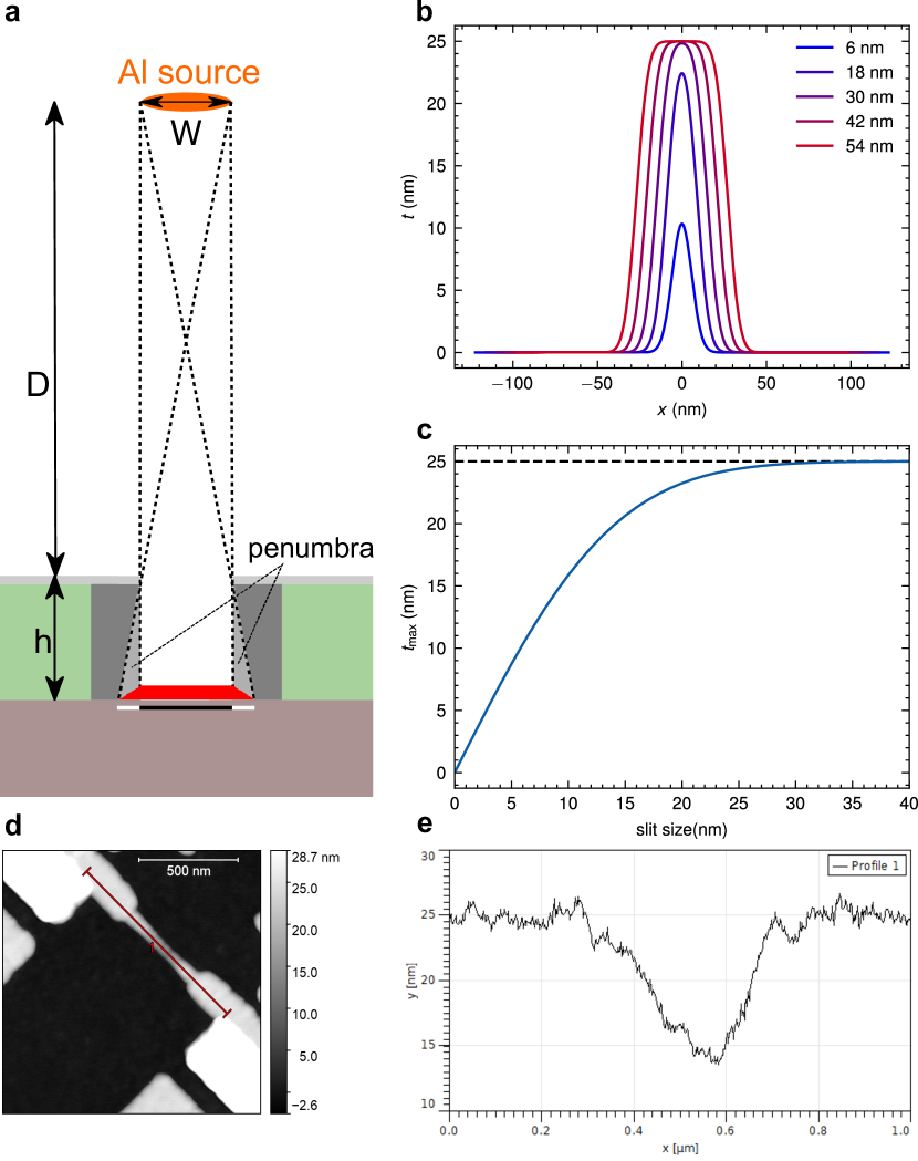
The width of the evaporated aluminum constrictions should be minimal to increase the coupling. As shown in Extended Data Fig. 3, constrictions may manifest a penumbra effect when the germanium mask slit is sufficiently thin. This occurs when the viewing angle of the extended source is larger than the angle of the slit opening seen from the substrate surface. By conservation of matter, the quantity of evaporated aluminum passing through the slit is always given by where is the width of the slit and is the thickness of evaporated aluminum. However, the aluminum is evaporated over a broadened zone on the substrate, resulting in partially evaporated regions (penumbra effect). The resulting profile can be computed as a convolution of the slit with the gaussian distribution of the source width. In Extended Data Fig. 3b, we show the broadened profile evaporated on the substrate as a function of the slit width, assuming , coming from a source with a gaussian distribution of diameter at a distance and a mask suspended at height . The maximum thickness of the profile grows with the slit width (see Extended Data Fig. 3c) and saturates only above a certain slit size . The minimal width is . We show an AFM micrograph of a typical constriction. The height profile of the constriction along the cut indicated in Extended Data Fig. 3d is shown in Extended Data Fig. 3e and illustrates the penumbra effect.
1.3 Dynamical coupling between the flux qubit and an arbitrary two-level system
In this work, we use a coupling scheme which can be turned on and off by the application of a microwave tone. In the spirit of Ref. [35], we consider that the flux qubit is biased at its optimal point and coupled to a two-level system by a coupling constant which is several orders of magnitude smaller than the detuning between the resonance frequencies of the two systems. One applies a resonant Rabi drive on the flux qubit. The driven Hamiltonian can be written as
Under unitary transformation and after rotating wave approximation, we get
In the eigenbasis of , the above operators can be replaced by
In this basis can be written as
The expression of operators , , , under unitary transformation can be easily estimated using Baker Campbell Hausdorff formula
Therefore under this transformation, the Hamiltonian becomes
If , only two terms of this Hamiltonian will be time independent, giving rise to an effective Hamiltonian
References
- \bibcommenthead
- Zwanenburg et al. [2013] Zwanenburg, F.A., Dzurak, A.S., Morello, A., Simmons, M.Y., Hollenberg, L.C.L., Klimeck, G., Rogge, S., Coppersmith, S.N., Eriksson, M.A.: Silicon quantum electronics. Rev. Mod. Phys. 85, 961–1019 (2013) https://doi.org/10.1103/RevModPhys.85.961
- Burkard et al. [2023] Burkard, G., Ladd, T.D., Pan, A., Nichol, J.M., Petta, J.R.: Semiconductor spin qubits. Rev. Mod. Phys. 95, 025003 (2023) https://doi.org/10.1103/RevModPhys.95.025003
- Muhonen et al. [2014] Muhonen, J.T., Dehollain, J.P., Laucht, A., Hudson, F.E., Kalra, R., Sekiguchi, T., Itoh, K.M., Jamieson, D.N., McCallum, J.C., Dzurak, A.S., Morello, A.: Storing quantum information for 30 seconds in a nanoelectronic device. Nature Nanotechnology 9(12), 986–991 (2014) https://doi.org/10.1038/nnano.2014.211
- Samkharadze et al. [2018] Samkharadze, N., Zheng, G., Kalhor, N., Brousse, D., Sammak, A., Mendes, U.C., Blais, A., Scappucci, G., Vandersypen, L.M.K.: Strong spin-photon coupling in silicon. Science 359(6380), 1123–1127 (2018) https://doi.org/10.1126/science.aar4054
- Landig et al. [2018] Landig, A.J., Koski, J.V., Scarlino, P., Mendes, U.C., Blais, A., Reichl, C., Wegscheider, W., Wallraff, A., Ensslin, K., Ihn, T.: Coherent spin–photon coupling using a resonant exchange qubit. Nature 560(7717), 179–184 (2018) https://doi.org/10.1038/s41586-018-0365-y
- Harvey-Collard et al. [2022] Harvey-Collard, P., Dijkema, J., Zheng, G., Sammak, A., Scappucci, G., Vandersypen, L.M.K.: Coherent spin-spin coupling mediated by virtual microwave photons. Phys. Rev. X 12, 021026 (2022) https://doi.org/10.1103/PhysRevX.12.021026
- Kane [1998] Kane, B.E.: A silicon-based nuclear spin quantum computer. Nature 393(6681), 133–137 (1998) https://doi.org/10.1038/30156
- He et al. [2019] He, Y., Gorman, S.K., Keith, D., Kranz, L., Keizer, J.G., Simmons, M.Y.: A two-qubit gate between phosphorus donor electrons in silicon. Nature 571(7765), 371–375 (2019) https://doi.org/10.1038/s41586-019-1381-2
- Xiang et al. [2013] Xiang, Z.-L., Ashhab, S., You, J.Q., Nori, F.: Hybrid quantum circuits: Superconducting circuits interacting with other quantum systems. Rev. Mod. Phys. 85, 623–653 (2013) https://doi.org/10.1103/RevModPhys.85.623
- Kurizki et al. [2015] Kurizki, G., Bertet, P., Kubo, Y., Mølmer, K., Petrosyan, D., Rabl, P., Schmiedmayer, J.: Quantum technologies with hybrid systems. Proceedings of the National Academy of Sciences 112(13), 3866–3873 (2015) https://doi.org/10.1073/pnas.1419326112
- Morello et al. [2020] Morello, A., Pla, J.J., Bertet, P., Jamieson, D.N.: Donor spins in silicon for quantum technologies. Advanced Quantum Technologies 3(11) (2020) https://doi.org/10.1002/qute.202000005
- Haikka et al. [2017] Haikka, P., Kubo, Y., Bienfait, A., Bertet, P., Molmer, K.: Proposal for detecting a single electron spin in a microwave resonator. Phys. Rev. A 95, 022306 (2017) https://doi.org/10.1103/PhysRevA.95.022306
- Lee [2019] Lee, M.: Ultrahigh-quality-factor superconducting microwave resonator on diamond for quantum information processing. Japanese Journal of Applied Physics 58(10), 100914 (2019) https://doi.org/%****␣main_resub_with_ref.tex␣Line␣1125␣****10.7567/1347-4065/ab45ac
- Viennot et al. [2015] Viennot, J.J., Dartiailh, M.C., Cottet, A., Kontos, T.: Coherent coupling of a single spin to microwave cavity photons. Science 349(6246), 408–411 (2015) https://doi.org/10.1126/science.aaa3786
- Mi et al. [2017] Mi, X., Cady, J.V., Zajac, D.M., Deelman, P.W., Petta, J.R.: Strong coupling of a single electron in silicon to a microwave photon. Science 355(6321), 156–158 (2017) https://doi.org/10.1126/science.aal2469
- Mi et al. [2018] Mi, X., Benito, M., Putz, S., Zajac, D.M., Taylor, J.M., Burkard, G., Petta, J.R.: A coherent spin–photon interface in silicon. Nature 555(7698), 599–603 (2018) https://doi.org/10.1038/nature25769
- Marcos et al. [2010] Marcos, D., Wubs, M., Taylor, J.M., Aguado, R., Lukin, M.D., Sørensen, A.S.: Coupling nitrogen-vacancy centers in diamond to superconducting flux qubits. Phys. Rev. Lett. 105, 210501 (2010) https://doi.org/10.1103/PhysRevLett.105.210501
- Twamley and Barrett [2010] Twamley, J., Barrett, S.D.: Superconducting cavity bus for single nitrogen-vacancy defect centers in diamond. Phys. Rev. B 81, 241202 (2010) https://doi.org/10.1103/PhysRevB.81.241202
- Zhu et al. [2011] Zhu, X., Saito, S., Kemp, A., Kakuyanagi, K., Karimoto, S.-i., Nakano, H., Munro, W.J., Tokura, Y., Everitt, M.S., Nemoto, K., Kasu, M., Mizuochi, N., Semba, K.: Coherent coupling of a superconducting flux qubit to an electron spin ensemble in diamond. Nature 478(7368), 221–224 (2011) https://doi.org/10.1038/nature10462
- Mooij et al. [1999] Mooij, J.E., Orlando, T.P., Levitov, L., Tian, L., Wal, C.H., Lloyd, S.: Josephson persistent-current qubit. Science 285(5430), 1036–1039 (1999) https://doi.org/10.1126/science.285.5430.1036
- Orlando et al. [1999] Orlando, T.P., Mooij, J.E., Tian, L., Wal, C.H., Levitov, L.S., Lloyd, S., Mazo, J.J.: Superconducting persistent-current qubit. Phys. Rev. B 60, 15398–15413 (1999) https://doi.org/10.1103/PhysRevB.60.15398
- Chiorescu et al. [2003] Chiorescu, I., Nakamura, Y., Harmans, C.J.P.M., Mooij, J.E.: Coherent quantum dynamics of a superconducting flux qubit. Science 299(5614), 1869–1871 (2003) https://doi.org/10.1126/science.1081045
- Bertet et al. [2005] Bertet, P., Chiorescu, I., Burkard, G., Semba, K., Harmans, C.J.P.M., DiVincenzo, D.P., Mooij, J.E.: Dephasing of a superconducting qubit induced by photon noise. Phys. Rev. Lett. 95, 257002 (2005) https://doi.org/10.1103/PhysRevLett.95.257002
- Yoshihara et al. [2006] Yoshihara, F., Harrabi, K., Niskanen, A.O., Nakamura, Y., Tsai, J.S.: Decoherence of flux qubits due to flux noise. Phys. Rev. Lett. 97, 167001 (2006) https://doi.org/10.1103/PhysRevLett.97.167001
- Bylander et al. [2011] Bylander, J., Gustavsson, S., Yan, F., Yoshihara, F., Harrabi, K., Fitch, G., Cory, D.G., Nakamura, Y., Tsai, J.-S., Oliver, W.D.: Noise spectroscopy through dynamical decoupling with a superconducting flux qubit. Nature Physics 7(7), 565–570 (2011) https://doi.org/10.1038/nphys1994
- Stern et al. [2014] Stern, M., Catelani, G., Kubo, Y., Grezes, C., Bienfait, A., Vion, D., Esteve, D., Bertet, P.: Flux qubits with long coherence times for hybrid quantum circuits. Phys. Rev. Lett. 113, 123601 (2014) https://doi.org/10.1103/PhysRevLett.113.123601
- Yan et al. [2016] Yan, F., Gustavsson, S., Kamal, A., Birenbaum, J., Sears, A.P., Hover, D., Gudmundsen, T.J., Rosenberg, D., Samach, G., Weber, S., Yoder, J.L., Orlando, T.P., Clarke, J., Kerman, A.J., Oliver, W.D.: The flux qubit revisited to enhance coherence and reproducibility. Nature Communications 7(1) (2016) https://doi.org/10.1038/ncomms12964
- Chang et al. [2022] Chang, T., Holzman, I., Cohen, T., Johnson, B.C., Jamieson, D.N., Stern, M.: Reproducibility and gap control of superconducting flux qubits. Phys. Rev. Appl. 18, 064062 (2022) https://doi.org/10.1103/PhysRevApplied.18.064062
- Holmes et al. [2019] Holmes, D., Lawrie, W.I.L., Johnson, B.C., Asadpoordarvish, A., McCallum, J.C., McCamey, D.R., Jamieson, D.N.: Activation and electron spin resonance of near-surface implanted bismuth donors in silicon. Phys. Rev. Mater. 3, 083403 (2019) https://doi.org/10.1103/PhysRevMaterials.3.083403
- Wolfowicz et al. [2013] Wolfowicz, G., Tyryshkin, A.M., George, R.E., Riemann, H., Abrosimov, N.V., Becker, P., Pohl, H.-J., Thewalt, M.L.W., Lyon, S.A., Morton, J.J.L.: Atomic clock transitions in silicon-based spin qubits. Nature Nanotechnology 8(8), 561–564 (2013) https://doi.org/%****␣main_resub_with_ref.tex␣Line␣1450␣****10.1038/nnano.2013.117
- Ranjan et al. [2021] Ranjan, V., Albanese, B., Albertinale, E., Billaud, E., Flanigan, D., Pla, J.J., Schenkel, T., Vion, D., Esteve, D., Flurin, E., Morton, J.J.L., Niquet, Y.M., Bertet, P.: Spatially resolved decoherence of donor spins in silicon strained by a metallic electrode. Phys. Rev. X 11, 031036 (2021) https://doi.org/%****␣main_resub_with_ref.tex␣Line␣1475␣****10.1103/PhysRevX.11.031036
- George et al. [2010] George, R.E., Witzel, W., Riemann, H., Abrosimov, N.V., Nötzel, N., Thewalt, M.L.W., Morton, J.J.L.: Electron spin coherence and electron nuclear double resonance of bi donors in natural si. Phys. Rev. Lett. 105, 067601 (2010) https://doi.org/10.1103/PhysRevLett.105.067601
- Bienfait et al. [2015] Bienfait, A., Pla, J.J., Kubo, Y., Stern, M., Zhou, X., Lo, C.C., Weis, C.D., Schenkel, T., Thewalt, M.L.W., Vion, D., Esteve, D., Julsgaard, B., Molmer, K., Morton, J.J.L., Bertet, P.: Reaching the quantum limit of sensitivity in electron spin resonance. Nature Nanotechnology 11(3), 253–257 (2015) https://doi.org/10.1038/nnano.2015.282
- Bienfait et al. [2016] Bienfait, A., Pla, J.J., Kubo, Y., Zhou, X., Stern, M., Lo, C.C., Weis, C.D., Schenkel, T., Vion, D., Esteve, D., Morton, J.J.L., Bertet, P.: Controlling spin relaxation with a cavity. Nature 531(7592), 74–77 (2016) https://doi.org/10.1038/nature16944
- Douce et al. [2015] Douce, T., Stern, M., Zagury, N., Bertet, P., Milman, P.: Coupling a single nitrogen-vacancy center to a superconducting flux qubit in the far-off-resonance regime. Phys. Rev. A 92, 052335 (2015) https://doi.org/10.1103/PhysRevA.92.052335
- Abdurakhimov et al. [2020] Abdurakhimov, L.V., Mahboob, I., Toida, H., Kakuyanagi, K., Matsuzaki, Y., Saito, S.: Driven-state relaxation of a coupled qubit-defect system in spin-locking measurements. Phys. Rev. B 102, 100502 (2020) https://doi.org/10.1103/PhysRevB.102.100502
- Pla et al. [2012] Pla, J.J., Tan, K.Y., Dehollain, J.P., Lim, W.H., Morton, J.J.L., Jamieson, D.N., Dzurak, A.S., Morello, A.: A single-atom electron spin qubit in silicon. Nature 489(7417), 541–545 (2012) https://doi.org/%****␣main_resub_with_ref.tex␣Line␣1600␣****10.1038/nature11449
- Shalibo et al. [2010] Shalibo, Y., Rofe, Y., Shwa, D., Zeides, F., Neeley, M., Martinis, J.M., Katz, N.: Lifetime and coherence of two-level defects in a josephson junction. Phys. Rev. Lett. 105, 177001 (2010) https://doi.org/10.1103/PhysRevLett.105.177001
- Lisenfeld et al. [2016] Lisenfeld, J., Bilmes, A., Matityahu, S., Zanker, S., Marthaler, M., Schechter, M., Schön, G., Shnirman, A., Weiss, G., Ustinov, A.V.: Decoherence spectroscopy with individual two-level tunneling defects. Scientific Reports 6(1) (2016) https://doi.org/10.1038/srep23786
- Spiecker et al. [2023] Spiecker, M., Paluch, P., Gosling, N., Drucker, N., Matityahu, S., Gusenkova, D., Günzler, S., Rieger, D., Takmakov, I., Valenti, F., Winkel, P., Gebauer, R., Sander, O., Catelani, G., Shnirman, A., Ustinov, A.V., Wernsdorfer, W., Cohen, Y., Pop, I.M.: Two-level system hyperpolarization using a quantum szilard engine. Nature Physics 19(9), 1320–1325 (2023) https://doi.org/10.1038/s41567-023-02082-8
- Pica et al. [2014] Pica, G., Wolfowicz, G., Urdampilleta, M., Thewalt, M.L.W., Riemann, H., Abrosimov, N.V., Becker, P., Pohl, H.-J., Morton, J.J.L., Bhatt, R.N., Lyon, S.A., Lovett, B.W.: Hyperfine stark effect of shallow donors in silicon. Phys. Rev. B 90, 195204 (2014) https://doi.org/10.1103/PhysRevB.90.195204
- Mansir et al. [2018] Mansir, J., Conti, P., Zeng, Z., Pla, J.J., Bertet, P., Swift, M.W., Walle, C.G., Thewalt, M.L.W., Sklenard, B., Niquet, Y.M., Morton, J.J.L.: Linear hyperfine tuning of donor spins in silicon using hydrostatic strain. Phys. Rev. Lett. 120, 167701 (2018) https://doi.org/10.1103/PhysRevLett.120.167701
- Pla et al. [2018] Pla, J.J., Bienfait, A., Pica, G., Mansir, J., Mohiyaddin, F.A., Zeng, Z., Niquet, Y.M., Morello, A., Schenkel, T., Morton, J.J.L., Bertet, P.: Strain-induced spin-resonance shifts in silicon devices. Phys. Rev. Appl. 9, 044014 (2018) https://doi.org/10.1103/PhysRevApplied.9.044014
- Holmes et al. [2021] Holmes, D., Johnson, B.C., Chua, C., Voisin, B., Kocsis, S., Rubanov, S., Robson, S.G., McCallum, J.C., McCamey, D.R., Rogge, S., Jamieson, D.N.: Isotopic enrichment of silicon by high fluence ion implantation. Phys. Rev. Mater. 5, 014601 (2021) https://doi.org/10.1103/PhysRevMaterials.5.014601
- Farfurnik et al. [2017] Farfurnik, D., Aharon, N., Cohen, I., Hovav, Y., Retzker, A., Bar-Gill, N.: Experimental realization of time-dependent phase-modulated continuous dynamical decoupling. Phys. Rev. A 96, 013850 (2017) https://doi.org/10.1103/PhysRevA.96.013850
Acknowledgements This research was supported by the Israeli Science Foundation under grant numbers 426/15, 898/19 and 963/19. We acknowledge T. Schenkel for kindly providing us with the isotopically purified Isonics wafer used in this work. M. Stern wishes to thank P. Bertet for fruitful discussions all over the years and A. Morello for his good advice “gates are your friends !”.