Upconversion of Phonon Modes into Microwave Photons in a Lithium Niobate Bulk Acoustic Wave Resonator Coupled to a Microwave Cavity
Abstract
The coupling between acoustic vibrations in a lithium niobate bulk acoustic wave resonator and microwave photons of a re-entrant microwave cavity was investigated at a temperature close to 4 K. Coupling was achieved by placing the acoustic resonator in the location of the re-entrant cavity electric field maxima, in a symmetric “split-post” configuration, with a large overlap between the microwave field and the acoustic mode, allowing acoustic modulations of the microwave frequency. We show that the acoustic modes in this setup retain large inherent quality factors of greater than . A maximum optomechanical coupling rate was determined to be = 0.014 mHz, four orders of magnitude larger than previous results obtained using a quartz BAW at 4 K in a similar experimental setup, but using a single post-re-entrant cavity resonator.
Investigating the fundamental interaction between photonic and phononic systems is crucial for advancing various applications within the domain of quantum technology and quantum electrodynamics [1, 2]. This understanding has led to the emergence of numerous associated predicted phenomena. Resolved sideband cooling [3, 4], parametric amplification [5, 6, 7], optomechanically induced transparency/absorption [8, 6], and long-range entanglement [9, 10], are just a few of these phenomena that have had important ramifications for testing fundamental quantum limits [11, 12, 13, 14, 15], dark matter detection [16, 17, 18], quantum communication, information processing and storage, along with generation and manipulation of quantum states [19, 20, 21]. Importantly for these systems, highly coherent quantum state readouts and increased coupling rates are integral for parametric detection techniques. This is particularly relevant in the search for gravitons [22, 23] and in the development of parametric transducers for achieving low noise readouts at microwave frequencies [3, 24].
Ground state preparation of truly macroscopic (gram-scale) mechanical resonators is a highly sought after experimental demonstration [12, 25, 26]. For one, there still remain questions regarding the quantum-to-classical crossover point which will be revealed by such systems, but in addition, precision readout of such devices may offer insights into quantum gravity and high frequency gravitational wave detection. [27, 28, 13, 29, 30, 31].

Studies on these photon-phonon interactions employ various types of resonant photonic device architectures, such as superconducting circuits [32], co-planar resonators [33], 3-D microwave cavity resonators [34], and whispering gallery resonators [35, 21, 36], combined with various types of mechanical architectures displaying high coupling rates, such as membrane-in-the-middle systems [6], trapped ion particles [37], and acoustic-mechanical modes such as bulk acoustic wave (BAW) resonators [25, 35, 6, 26]. BAW resonators are low-loss mechanical resonators that exhibit long mechanical coherence times due to their specifically engineered convex surface, which helps trap the majority of phonons in the centre of the resonator[27].
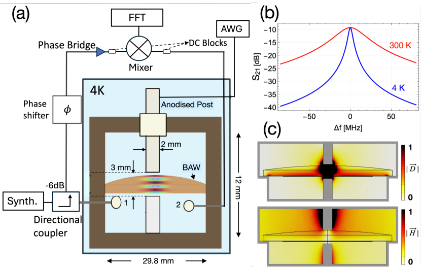
In this work, a macroscopic centimetre size-scale lithium niobate (LiNbO3) crystal with its axis cut in the z-direction was manufactured with a diameter of 30 mm, a centre thickness of 2 mm and a convex radius of curvature of 100 mm. The crystal exhibited coherent phonon modes trapped in the centre of the crystal with frequencies of order MHz. Fig.1 shows a photo of the LiNbO3 crystal along with the two halves of a “split-post” microwave cavity resonator[38], which sandwiches the BAW in the post gap allowing maximum electric field to be applied to the region of maximum phonon trapping as shown in Fig. 2. This means the acoustic phonons will be parametrically upconverted to microwave frequencies. The motivation was drawn from similar experiments conducted with quartz BAW resonators[39, 26]. However, the cavity design differs from before as we have used a symmetric design in which the gap is located in the centre of a co-axial cavity. This particular design results in a more highly confined electric field distribution focused into the centre of the BAW, and we term this design the “split-post re-entrant cavity”. Moreover, the reason for the emerging popularity of LiNbO3 over quartz is that it exhibits a stronger piezoelectric coefficient in addition to a low loss tangent. For example, LiNbO3-BAW has demonstrated a high quality factor frequency product, of 1014 Hz at room temperature[40].
Much smaller LiNbO3 nanostructures have been used previously in various optical applications, such as quantum sensors [41, 42] and optical transducers [43, 44, 45, 46, 47, 48]. Our study investigated LiNbO3 microwave-BAW coupling rates, with the goal of creating strongly coupled coherent microwave readout of large macroscopic phonon modes for fundamental physics applications that require larger masses. Here upconversion opens up possibilities for harnessing effects such as parametric amplification, cooling, and squeezing, while also providing a method for reading out displacement in large non-piezoelectric crystals.
To model the photon-phonon interaction, the dynamics are characterized by the following Hamiltonian[1]:
| (1) |
where and are the bosonic annihilation (creation) operators of the microwave and the acoustic resonance, at frequencies and , respectively, and is the optomechnical coupling rate.
The Hamiltonian in (1) describes the interaction between a microwave electric field between the two posts and the acoustic phonon mode of the BAW device, which results in radiation pressure acting on the acoustic modes. This radiation pressure displaces the oscillator (by displacement ) and leads to parametric modulation of the microwave cavity fields as shown in (2), where the second term on the RHS represents the linear coupling, which can be implemented as a displacement readout[1]:
| (2) |
Furthermore, we can define the following quantities:
| (3) |
where , also known as the frequency pull factor, is measured from the experimental data and helps evaluate , which is the photon-phonon coupling rate, also known as the single photon coupling rate. Additionally, is the zero-point fluctuation of the mechanical resonance, where is the reduced Planck’s constant, and is the effective mode mass.
Fig. 2(a) illustrates the experimental setup for measurements conducted at 4 K. The experiment utiizes the split post microwave cavity, which functions as a frequency discriminator. This phase bridge detects frequency shifts of the cavity in response to mechanical modes by ensuring that the LO and RF signals are in quadrature, making the system insensitive to amplitude fluctuations. The power splitting ratio is set by a -6dB directional coupler. The signal generator is an analog synthesizer (Keysight E8663D), covering the frequency range of 100 kHz to 9 GHz. Thus the experiment measures the frequency modulation of the BAW resonator up-converted to microwave frequencies. The output of the mixer is observed on the FFT spectrum analyser.
The set-up in Fig. 2 also shows the two posts of the microwave cavity, one of which was anodised to provide two electrically isolated posts allowing them to function as electrodes to piezoelectrically excite the BAW mechanical modes with an arbitrary waveform generator (AWG). Since the applied voltage to the electrodes is known, we can estimate the piezoelectric-induced crystal displacement using known LiNbO3 electrostatic material parameters, allowing us to determine the change in displacement . The measured change in microwave cavity frequency, , is then used to determine .
It is known that for piezoelectric materials, the mechanical displacement is proportional to the charge on the surface [1]. In our set up, this charge is enhanced due to the split post geometry and is given by, , where, is the effective piezoelectric coupling constant defined using the Butterworth-Van Dyke (BWD) model, which can be understood from the BAW-resonator lumped circuit element theory[49]. For a mechanical mode, , relations between piezoelectric constant and the corresponding LCR circuit elements of the BWD model are represented as[28]:
| (4) |
Here, is the mode quality factor, the motional resistance, and and the effective inductance and capacitance respectively. Similarly, the current from the equivalent BAW circuit model may be presented in terms of mechanical resonance as:
| (5) |
Thus, the values of motional resistance could be measured at 4 K using an impedance analyser.
The operational cavity mode was the fundamental split-post-mode (Fig. 2c), with a frequency of 6.075 GHz at 4 K. The loaded quality factor, , improved significantly from 300 to 4 K, to 330 to 2500 respectively, due to reduced resistive losses from the copper cavity walls as shown in Fig. 2b. The coupling coefficients were determined from reflection measurements form ports 1 and to, and calculated to be and . Thus the unloaded microwave -factor can thus be determined to be .The increased -factor helped achieve better discriminator sensitivity for the phase bridge setup. The incident input power to the microwave cavity was 0.01 mW.
The change in the displacement of the mechanical mode is given by the simple relationship between the calculated displacement and the change in the output voltage from the mixer, as follows:
| (6) |
where is the discriminator sensitivity (phase-bridge); the ratio at which frequency fluctuations are converted to synchronous voltage fluctuations in the readout, while is the frequency pull factor introduced previously and is evaluated from the voltage response output from the mixer corresponding to the displacement of mechanical resonance.
From (1), we can also calculate in terms of :
| (7) |
Driving an applied time varying MHz signal across the split-posts, piezoelectrically exciting the BAW, while simultaneously driving the microwave cavity at its resonant frequency, yields a mechanically induced frequency modulation of the microwave pump frequency, producing side bands on the microwave carrier. This is triggered by the induced displacement of the LiNbO3 BAW when tuned to the acoustic modes. Due to the trigonal symmetry of lithium niobate, two-mode families exist. ‘A’ refers to longitudinal polarization, where bulk displacement occurs in the z-direction, while ‘B’ denotes a shear wave polarized mode with dominant displacement in the x-y plane. The first subscript refers to the fundamental polarization inside the BAW resonator, which has been studied in [40]. More details of the different suffixes in the modes can be found in [27]. In this work, we study the A3,0,0 and A5,0,0 longitudinal modes, and B5,0,0, B7,0,0, B9,0,0 shear modes.
Fig. 3 c) and d) shows the mixer output voltages for the longitudinal A5,0,0 mode and the shear B7,0,0 modes respectively. Normalised reflection coefficients S11 are measured by driving the BAW through the anodised post and measuring the reflected power on an impedance analyser, which is shown as the green trace. Fig. 3 illustrates that the mixer output voltage is indeed a result of the mechanical mode being driven.
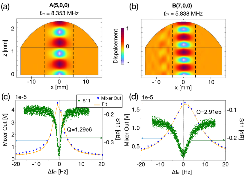
We can determine the linewidth of the mechanical modes from the mixer output voltage and obtain -factors. These values closely agree with the previously measured at 4 K using a parallel cathode plate [40]. Fig. 4 shows measured mechanical -factors at 4 K for various A and B modes.
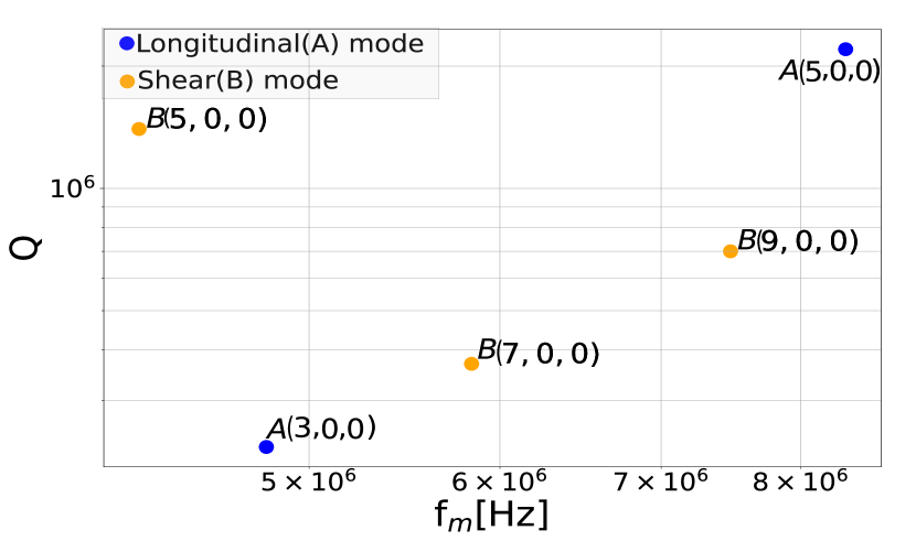
The effective mode mass for various A and B modes of the BAW vary slightly from each other, depending on the value of their lumped circuit parameters. These values were calculated using COMSOL finite element modelling, similar to the analysis for quartz, as detailed in the works of [26, 12], and related analytical effective mass calculations by [50, 51], with details given in Appendix .1. Various determined parameters for each of the mechanical modes are presented in Table 1, where co-operativity is defined as , is the line width of the mechanical resonance and is the linewidth of the microwave cavity [1]. As observed, different modes show different coupling rates due to different displacement polarisations and different overlaps between the re-entrant post-mode and the mechanical modes.
| B5,0,0 | 4.20 | 3.53 | 2.67 | 2.40 | |
| A3,0,0 | 4.70 | 4.15 | 1.44 | 2.40 | |
| B7,0,0 | 5.80 | 3.14 | 2.12 | 2.96 | |
| B9,0,0 | 7.40 | 2.77 | 4.79 | 7.62 | |
| A5,0,0 | 8.30 | 3.52 | 2.38 | 1.96 |
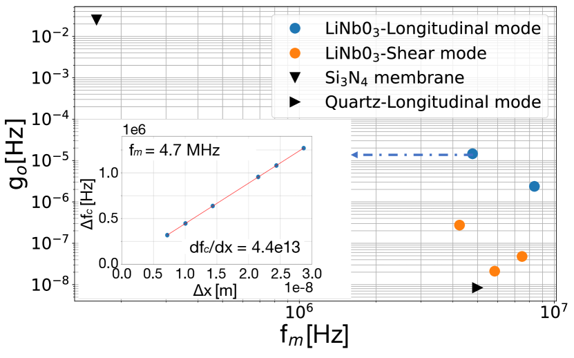
The displacement of the crystal structure is calculated from the electrical current arising from the applied piezoelectric voltage using equations (4) and (5). The frequency shift from the phase bridge measurement divided by the calculated piezoelectric induced displacement provides the frequency pull factor, as detailed by equations (6) and (7). By measuring for different input voltages to the piezoelectric BAW (converted to displacements), coupling rates at 4 K for different modes were calculated from the gradients of . Fig. 5 shows coupling rates for A and B modes of LiNbO3-BAW, compared to other mechanical resonators. The inset figure shows for the mode and is equal to 4.4 1013 Hz/m. The coupling rate is derived from this value by multiplying it with .
The value of these coupling rates is benchmarked against similar experiments using a quartz BAW at 4 K with a single post-re-entrant resonator, as described in [26, 39]. The coupling rates for LiNbO3-BAW in the split-post re-entrant cavity are observed to be up to four orders of magnitude greater compared to quartz for the longitudinal mode at A3,0,0, demonstrating higher coupling rates and making it a suitable candidate for further studies. Additionally, we compared our results with a Si3N4 membrane inside a re-entrant cavity, which achieved coupling rates of 25 mHz [6]. These findings motivate further investigation into the coupling of LiNbO3-BAW with photonic systems.
The degree to which the electromagnetic and mechanical mode volumes overlap plays a key role in determining the optomechanical coupling. The improvement in coupling rates resulting from the use of a split-post versus a single-post cavity can be estimated by the ratios of a so-called overlap factor. This factor can be determined from the percentage of electromagnetic mode that exists within the mechanical mode volume determined by the dashed lines in Fig. 3. The A5,0,0 mechanical mode, for example, has all of its displacement field within a diameter of approximately 6.0 mm. Inside this volume, the electromagnetic field distribution for both the split- and single-post cavities is primarily determined by the field, which makes up of the electrical energy, which is only 5 in the case of a single post. The amount of electrical field within the mechanical mode volume is 20 times larger for a split-post design compared to the single-post design, explaining one of the contributions to the observed coupling rate increase of these results compared to the results in quartz [26, 39]. The remaining contribution stems from the material properties.
In conclusion, we investigated the acoustic modes of a LiNbO3-BAW resonator by directly exciting them with a radio frequency external voltage at mechanical resonance through piezoelectricity at 4 K. Coupling rates of order 0.014 mHz were obtained for the A3,0,0 longitudinal mode, four orders of magnitude larger than previous results obtained using quartz. Thus, with further development, could be utilised as an alternate material in quantum sensing and communication, and testing of fundamental physics.
Acknowledgements.
This research was supported by the ARC Centre of Excellence for Engineered Quantum Systems (EQUS, No. CE170100009) along with support from the Defence Science and Technology Group (DSTG) as part of the EQUS Quantum Clock Flagship program. Additional support provided by the ARC Centre of Excellence for Dark Matter Particle Physics (CDM, No. CE200100008).Appendices
.1 Effective mass of the mechanical modes
Evaluation of mode mass was done using COMSOL, evaluating potential energy integral for 3D/2D model, for a given mode is given in terms of following equations.
| (8) |
The total potential energy of the mode is then given by, integral over the entire volume as represented by
| (9) |
Here material density is uniform and effective mass for a 3D model
| (10) |
This process begins by evaluating the point displacement at the calculation point, as in the case of the odd mode, where the displacement at the point of maximum displacement is used to normalize the displacement function . The integral of the normalized displacement over the entire geometry of the resonator is then multiplied by to obtain the effective mass (our model in COMSOL was a 2D axisymmetrical model). By investigating the potential energy U for any mode with a small volume element dV centred on the potential energy centred around the mass element and is defined as below, where m is defined as effective modal mass for a given mode m.
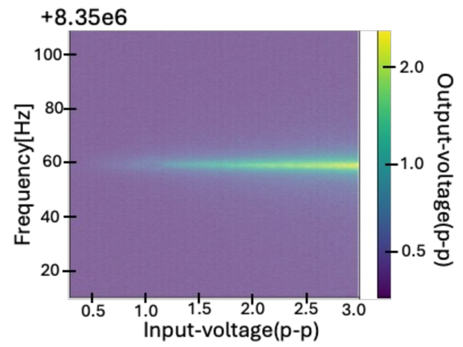
.2 Power dependence of the mechanical mode
Fig. 6 shows the density plot for B(5,0,0) mode where the input voltage to the cavity is varied in the range of 0.1 V-3.0 V, and the output of the mixer is plotted for different input power. As the power is increased the amplitude of the sideband increases, however there is no significant change in line-width, which indicated no variation in Q-factor.
References
References
- Aspelmeyer, Kippenberg, and Marquardt [2014] M. Aspelmeyer, T. J. Kippenberg, and F. Marquardt, “Cavity optomechanics,” Reviews of Modern Physics 86, 1391 (2014).
- Blais et al. [2021] A. Blais, A. L. Grimsmo, S. M. Girvin, and A. Wallraff, “Circuit quantum electrodynamics,” Reviews of Modern Physics 93, 025005 (2021).
- Cuthbertson et al. [1996] B. Cuthbertson, M. Tobar, E. Ivanov, and D. Blair, “Parametric back-action effects in a high-Q cyrogenic sapphire transducer,” Review of Scientific Instruments 67, 2435–2442 (1996).
- Teufel et al. [2011] J. D. Teufel, T. Donner, D. Li, J. W. Harlow, M. S. Allman, K. Cicak, A. J. Sirois, J. D. Whittaker, K. W. Lehnert, and R. W. Simmonds, “Sideband cooling of micromechanical motion to the quantum ground state,” Nature 475, 359–363 (2011).
- Wilson et al. [2015] D. J. Wilson, V. Sudhir, N. Piro, R. Schilling, A. Ghadimi, and T. J. Kippenberg, “Measurement-based control of a mechanical oscillator at its thermal decoherence rate,” Nature 524, 325–329 (2015).
- Kumar et al. [2024] S. Kumar, M. Kenworthy, H. Ginn, and X. Rojas, “Optomechanically induced transparency/absorption in a 3D microwave cavity architecture at ambient temperature,” arXiv preprint arXiv:2402.10935 (2024).
- Xiong and Wu [2018] H. Xiong and Y. Wu, “Fundamentals and applications of optomechanically induced transparency,” Applied physics reviews 5 (2018).
- Agarwal and Huang [2010] G. S. Agarwal and S. Huang, “Electromagnetically induced transparency in mechanical effects of light,” Physical Review A—Atomic, Molecular, and Optical Physics 81, 041803 (2010).
- Yao et al. [2024] X. Yao, M. H. de Jong, J. Li, and S. Gröblacher, “Long-range optomechanical interactions in sin membrane arrays,” arXiv preprint arXiv:2408.03066 (2024).
- Palomaki et al. [2013] T. Palomaki, J. Teufel, R. Simmonds, and K. W. Lehnert, “Entangling mechanical motion with microwave fields,” Science 342, 710–713 (2013).
- Schrinski et al. [2023] B. Schrinski, Y. Yang, U. Von Lüpke, M. Bild, Y. Chu, K. Hornberger, S. Nimmrichter, and M. Fadel, “Macroscopic quantum test with bulk acoustic wave resonators,” Physical Review Letters 130, 133604 (2023).
- Bushev et al. [2019] P. Bushev, J. Bourhill, M. Goryachev, N. Kukharchyk, E. Ivanov, S. Galliou, M. Tobar, and S. Danilishin, “Testing the generalized uncertainty principle with macroscopic mechanical oscillators and pendulums,” Physical Review D 100, 066020 (2019).
- Campbell et al. [2023] W. M. Campbell, M. E. Tobar, M. Goryachev, and S. Galliou, “Improved constraints on minimum length models with a macroscopic low loss phonon cavity,” Physical Review D 108, 102006 (2023).
- Lo et al. [2016] A. Lo, P. Haslinger, E. Mizrachi, L. Anderegg, H. Müller, M. Hohensee, M. Goryachev, and M. E. Tobar, “Acoustic tests of Lorentz symmetry using quartz oscillators,” Physical Review X 6, 011018 (2016).
- Goryachev et al. [2018] M. Goryachev, Z. Kuang, E. N. Ivanov, P. Haslinger, H. Müller, and M. E. Tobar, “Next generation of phonon tests of Lorentz invariance using quartz baw resonators,” IEEE Transactions on Ultrasonics, Ferroelectrics, and Frequency Control 65, 991–1000 (2018).
- Arvanitaki, Dimopoulos, and Van Tilburg [2016] A. Arvanitaki, S. Dimopoulos, and K. Van Tilburg, “Sound of dark matter: searching for light scalars with resonant-mass detectors,” Physical review letters 116, 031102 (2016).
- Carney et al. [2021] D. Carney, A. Hook, Z. Liu, J. M. Taylor, and Y. Zhao, “Ultralight dark matter detection with mechanical quantum sensors,” New Journal of Physics 23, 023041 (2021).
- Campbell et al. [2021] W. M. Campbell, B. T. McAllister, M. Goryachev, E. N. Ivanov, and M. E. Tobar, “Searching for scalar dark matter via coupling to fundamental constants with photonic, atomic, and mechanical oscillators,” Physical Review Letters 126, 071301 (2021).
- Gokhale et al. [2020] V. J. Gokhale, B. P. Downey, D. S. Katzer, N. Nepal, A. C. Lang, R. M. Stroud, and D. J. Meyer, “Epitaxial bulk acoustic wave resonators as highly coherent multi-phonon sources for quantum acoustodynamics,” Nature communications 11, 2314 (2020).
- Chu et al. [2017] Y. Chu, P. Kharel, W. H. Renninger, L. D. Burkhart, L. Frunzio, P. T. Rakich, and R. J. Schoelkopf, “Quantum acoustics with superconducting qubits,” Science 358, 199–202 (2017).
- Salzenstein et al. [2010] P. Salzenstein, A. Kuna, L. Sojdr, and J. Chauvin, “Significant step in ultra high stability quartz crystal oscillators,” Electron. Lett 46, 1433–1434 (2010).
- Tobar et al. [2023] G. Tobar, S. K. Manikandan, T. Beitel, and I. Pikovski, “Detecting single gravitons with quantum sensing,” arXiv preprint arXiv:2308.15440 (2023).
- Tobar, Pikovski, and Tobar [2024] G. Tobar, I. Pikovski, and M. E. Tobar, “Detecting kHz gravitons from a neutron star merger with a multi-mode resonant bar,” arXiv preprint arXiv:2406.16898 (2024).
- Locke et al. [1998] C. Locke, M. Tobar, E. Ivanov, and D. Blair, “Parametric interaction of the electric and acoustic fields in a sapphire monocrystal transducer with a microwave readout,” Journal of applied physics 84, 6523–6527 (1998).
- Bourhill, Ivanov, and Tobar [2015] J. Bourhill, E. Ivanov, and M. Tobar, “Precision measurement of a low-loss cylindrical dumbbell-shaped sapphire mechanical oscillator using radiation pressure,” Physical Review A 92, 023817 (2015).
- Bourhill et al. [2020] J. Bourhill, N. d. C. Carvalho, M. Goryachev, S. Galliou, and M. E. Tobar, “Generation of coherent phonons via a cavity enhanced photonic lambda scheme,” Applied Physics Letters 117 (2020).
- Goryachev and Tobar [2014] M. Goryachev and M. E. Tobar, “Gravitational wave detection with high frequency phonon trapping acoustic cavities,” Physical Review D 90, 102005 (2014).
- Campbell, Goryachev, and Tobar [2023] W. M. Campbell, M. Goryachev, and M. E. Tobar, “The multi-mode acoustic gravitational wave experiment: Mage,” Scientific Reports 13, 10638 (2023).
- Goryachev et al. [2021] M. Goryachev, W. M. Campbell, I. S. Heng, S. Galliou, E. N. Ivanov, and M. E. Tobar, “Rare events detected with a bulk acoustic wave high frequency gravitational wave antenna,” Physical Review Letters 127, 071102 (2021).
- Singh et al. [2017] S. Singh, L. De Lorenzo, I. Pikovski, and K. Schwab, “Detecting continuous gravitational waves with superfluid 4He,” New Journal of Physics 19, 073023 (2017).
- Aggarwal et al. [2021] N. Aggarwal, O. D. Aguiar, A. Bauswein, G. Cella, S. Clesse, A. M. Cruise, V. Domcke, D. G. Figueroa, A. Geraci, M. Goryachev, et al., “Challenges and opportunities of gravitational-wave searches at mhz to ghz frequencies,” Living reviews in relativity 24, 1–74 (2021).
- Blais, Girvin, and Oliver [2020] A. Blais, S. M. Girvin, and W. D. Oliver, “Quantum information processing and quantum optics with circuit quantum electrodynamics,” Nature Physics 16, 247–256 (2020).
- Manenti et al. [2017] R. Manenti, A. F. Kockum, A. Patterson, T. Behrle, J. Rahamim, G. Tancredi, F. Nori, and P. J. Leek, “Circuit quantum acoustodynamics with surface acoustic waves,” Nature communications 8, 975 (2017).
- Kitzman et al. [2023] J. Kitzman, J. Lane, C. Undershute, M. Drimmer, A. Schleusner, N. Beysengulov, C. Mikolas, and J. Pollanen, “Free-space coupling and characterization of transverse bulk phonon modes in lithium niobate in a quantum acoustic device,” Applied Physics Letters 123 (2023).
- Schliesser and Kippenberg [2010] A. Schliesser and T. J. Kippenberg, “Cavity optomechanics with whispering-gallery mode optical micro-resonators,” in Advances In Atomic, Molecular, and Optical Physics, Vol. 58 (Elsevier, 2010) pp. 207–323.
- Locke and Tobar [2004] C. Locke and M. Tobar, “Measurement of the strain-induced coefficient of permittivity of sapphire using whispering gallery modes excited in a high-q acoustic sapphire oscillator,” Measurement Science and Technology 15, 2145 (2004).
- Kotler et al. [2017] S. Kotler, R. W. Simmonds, D. Leibfried, and D. J. Wineland, “Hybrid quantum systems with trapped charged particles,” Physical Review A 95, 022327 (2017).
- Le Floch et al. [2013] J.-M. Le Floch, Y. Fan, M. Aubourg, D. Cros, N. Carvalho, Q. Shan, J. Bourhill, E. Ivanov, G. Humbert, V. Madrangeas, et al., “Rigorous analysis of highly tunable cylindrical transverse magnetic mode re-entrant cavities,” Review of Scientific Instruments 84 (2013).
- Carvalho et al. [2019] N. Carvalho, J. Bourhill, M. Goryachev, S. Galliou, and M. Tobar, “Piezo-optomechanical coupling of a 3D microwave resonator to a bulk acoustic wave crystalline resonator,” Applied Physics Letters 115 (2019).
- Campbell et al. [2024] W. M. Campbell, S. Parashar, M. E. Tobar, and M. Goryachev, “Low temperature properties of low-loss macroscopic lithium niobate bulk acoustic wave resonators,” preprint arXiv:2407.17693 (2024).
- Marinkovic et al. [2021] I. Marinkovic, M. Drimmer, B. Hensen, and S. Groblacher, “Hybrid integration of silicon photonic devices on lithium niobate for optomechanical wavelength conversion,” Nano letters 21, 529–535 (2021).
- Cleland, Wollack, and Safavi-Naeini [2024] A. Y. Cleland, E. A. Wollack, and A. H. Safavi-Naeini, “Studying phonon coherence with a quantum sensor,” Nature Communications 15, 4979 (2024).
- Arrangoiz-Arriola et al. [2018] P. Arrangoiz-Arriola, E. A. Wollack, M. Pechal, J. D. Witmer, J. T. Hill, and A. H. Safavi-Naeini, “Coupling a superconducting quantum circuit to a phononic crystal defect cavity,” Physical Review X 8, 031007 (2018).
- Satzinger et al. [2018] K. J. Satzinger, Y. Zhong, H.-S. Chang, G. A. Peairs, A. Bienfait, M.-H. Chou, A. Cleland, C. R. Conner, É. Dumur, J. Grebel, et al., “Quantum control of surface acoustic-wave phonons,” Nature 563, 661–665 (2018).
- Shao et al. [2019] L. Shao, M. Yu, S. Maity, N. Sinclair, L. Zheng, C. Chia, A. Shams-Ansari, C. Wang, M. Zhang, K. Lai, and M. Lončar, “Microwave-to-optical conversion using lithium niobate thin-film acoustic resonators,” Optica 6, 1498–1505 (2019).
- Mirhosseini et al. [2020] M. Mirhosseini, A. Sipahigil, M. Kalaee, and O. Painter, “Superconducting qubit to optical photon transduction,” Nature 588, 599–603 (2020).
- Jiang et al. [2020] W. Jiang, C. J. Sarabalis, Y. D. Dahmani, R. N. Patel, F. M. Mayor, T. P. McKenna, R. Van Laer, and A. H. Safavi-Naeini, “Efficient bidirectional piezo-optomechanical transduction between microwave and optical frequency,” Nature Communications 11, 1166 (2020).
- Wollack et al. [2021] E. A. Wollack, A. Y. Cleland, P. Arrangoiz-Arriola, T. P. McKenna, R. G. Gruenke, R. N. Patel, W. Jiang, C. J. Sarabalis, and A. H. Safavi-Naeini, “Loss channels affecting lithium niobate phononic crystal resonators at cryogenic temperature,” Applied Physics Letters 118 (2021).
- Bible [2002] S. Bible, “Crystal oscillator basics and crystal selection for rfPICTM and PICmicro® devices,” Microchip Technology Inc (2002).
- Stevens and Tiersten [1986] D. Stevens and H. Tiersten, “An analysis of doubly rotated quartz resonators utilizing essentially thickness modes with transverse variation,” The Journal of the Acoustical Society of America 79, 1811–1826 (1986).
- Shi et al. [2014] J. Shi, C. Fan, M. Zhao, and J. Yang, “Variational formulation of the Stevens-Tiersten equation and application in the analysis of rectangular trapped-energy quartz resonators,” The Journal of the Acoustical Society of America 135, 175–181 (2014).