Leveraging Augmented Reality for Improved Situational Awareness During UAV-Driven Search and Rescue Missions
Abstract
In the high-stakes domain of search-and-rescue missions, the deployment of Unmanned Aerial Vehicles (UAVs) has become increasingly pivotal. These missions require seamless, real-time communication among diverse roles within response teams, particularly between Remote Operators (ROs) and On-Site Operators (OSOs). Traditionally, ROs and OSOs have relied on radio communication to exchange critical information, such as the geolocation of victims, hazardous areas, and points of interest. However, radio communication lacks information visualization, suffers from noise, and requires mental effort to interpret information, leading to miscommunications and misunderstandings. To address these challenges, this paper presents VizCom-AR, an Augmented Reality system designed to facilitate visual communication between ROs and OSOs and their situational awareness during UAV-driven search-and-rescue missions. Our experiments, focus group sessions with police officers, and field study showed that VizCom-AR enhances spatial awareness of both ROs and OSOs, facilitate geolocation information exchange, and effectively complement existing communication tools in UAV-driven emergency response missions. Overall, VizCom-AR offers a fundamental framework for designing Augmented Reality systems for large scale UAV-driven rescue missions.
I Introduction
Unmanned Aerial Vehicles (UAVs) are transforming public safety operations such as search and rescue [9], firefighting [8], and disaster relief, by providing an aerial perspective of the scene. For instance, law enforcement officers in California utilized smart UAVs to track a shooter, relying on live video feeds monitored by off-site officers. Similarly, during the Notre-Dame cathedral fire in Paris in 2019, UAVs equipped with thermal cameras were deployed in coordination with over 400 rescue team members [21]. The sheer size of the response highlights the need for effective communication between humans, smart UAVs, and between humans and UAVs during emergency situations [4].
During UAV-assisted public safety operations, specific team members, known as Remote Operators (ROs), analyze aerial video footage from the UAVs. This footage offers a bird’s-eye view of the scene, enhancing the ROs’ situational awareness and enabling them to identify and examine critical details of the environment. The ROs relay their insights to the On-Site Operators (OSOs), who are actively engaged in ground activities at the physical scene. In current practice, ROs and OSOs communicate via radio, exchanging vital Scene Information including geocoordinates of individuals in need of assistance, location of potential evidence that needs further investigation, and areas that might pose hazards for OSOs. Additionally, ROs provide planning advice to OSOs, guiding them on prioritizing targets to accomplish mission objectives efficiently and safely. OSOs also communicate their mission progress back to ROs.
The current public safety reliance upon radios, to relay essential scene information, presents unique challenges, particularly when communicating geolocation details such as the exact coordinates of a victim, evidence spots, or a suspect’s last known location. In our prior work [1], we conducted design sessions with Fire-fighters and found that sharing information in noisy environments via radio often results in miscommunication and misunderstandings, and therefore decreased operators’ situational awareness. In particular, we found that conveying geo-coordinates verbally introduced ambiguities due to the absence of visual context, interference on radio channels, and the cognitive load involved in accurately processing multiple sets of coordinates. During time-sensitive, critical situations, this lead to confusion, delays, and, loss of situational awareness. Moreover, radio communication makes it difficult to ensure consistent interpretation of the scene in large-scale rescue missions involving hundreds of team members [12]. These issues highlight the need for designing innovative systems that enable rescue team members to share and visualize precise geolocatable information during rescue and emergency response missions.
With the advancement of UAVs, Augmented Reality (AR) technology has also evolved, offering visualization support by overlaying digital information onto the real world. While AR has gained popularity in fields such as healthcare and education, its application in UAV-driven search and rescue missions remains under-explored. Addressing this research gap requires a collaborative effort across academia, industry, and rescue personnel to design effective, useful, and innovative solutions. Therefore, in this paper, we present our AR platform called VizCom-AR.
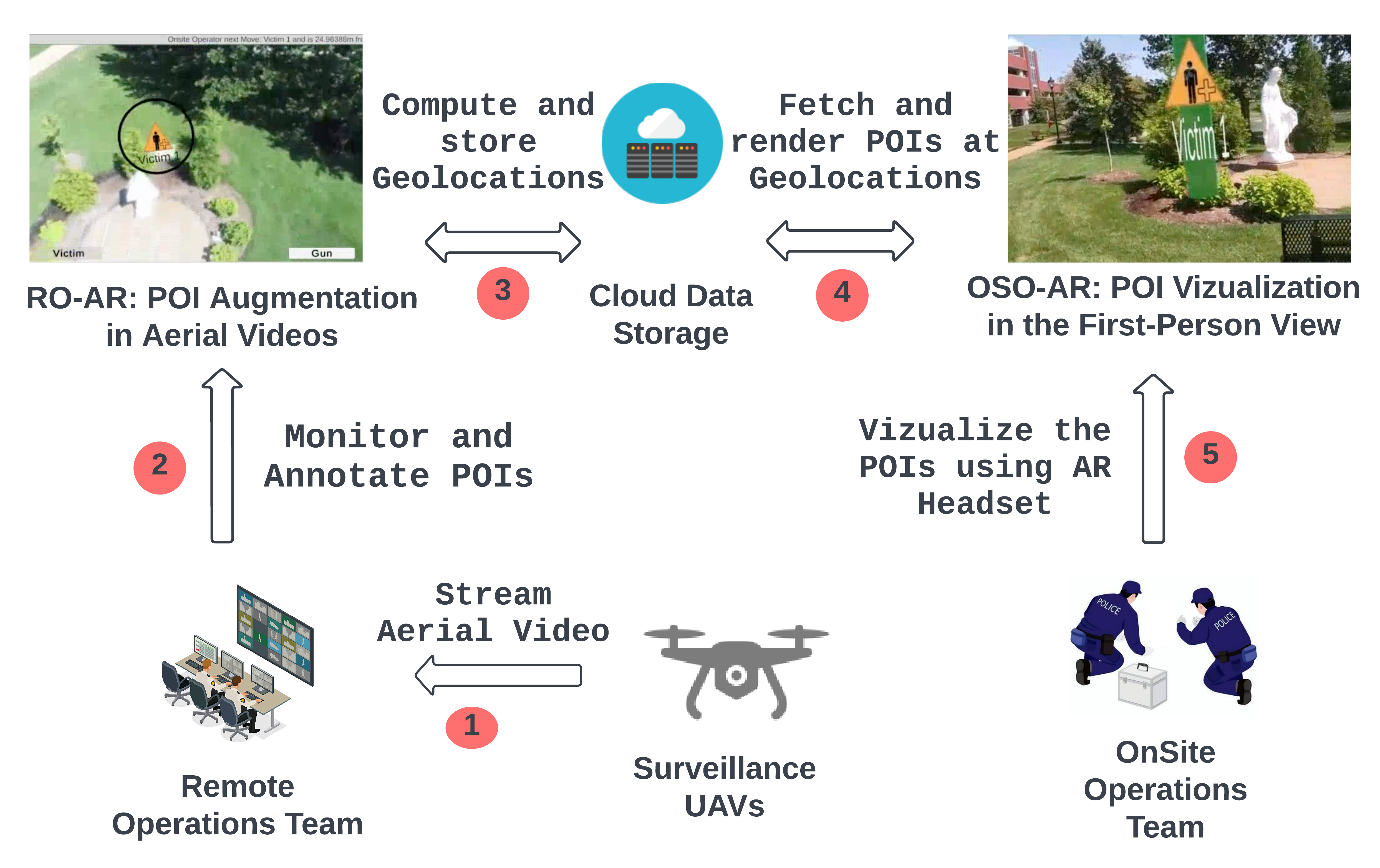
We utilize the paradigms of Location-based Augmented Reality to design VizCom-AR to help ROs and OSOs communicate scene information and maintain situational awareness. The design of VizCom-AR comprises two different AR applications: OSO-AR and RO-AR that together empower responders to share and visualize scene information according to the diverse needs of their specific roles. Figure 1 provides an overview of our system during a UAV-driven search-and-rescue operation. ROs use RO-AR to annotate the live video stream with Points of Interest (POIs), and OSOs use OSO-AR to vizualize the same POIs in their first-person view using AR-headset. We conducted multiple studies to learn the feasibility, usability, and end-users’ (police officers) perspective of our system. We found that VizCom-AR makes critical geolocation information more comprehensible, and that visualization of the geolocation improves the spatial understanding of the scene among the rescue team members. Further, a team of police officers indicated that VizCom-AR could effectively complement the existing radio communication infrastructure of their emergency rescue teams.
II Related Work
II-A Augmenting Reality Systems for Robots
The comprehensive survey conducted by Suzuki et al., [20], on AR-enhanced Robotic Interfaces, highlights various applications in which AR significantly enhances human-robot collaboration. For instance, Boateng et al.,[2] leveraged AR to enhance Team Situation Awareness in human-robot interactions. In the context of UAVs, Erat et al.,[6], used AR to simplify UAV path planning in spatially restricted settings by offering an exocentric viewpoint to operators, and Liu et al.,[11] developed an AR system for controlling an autonomous UAV using hand movements on a 3d Map augmented inside a Hololens.
Broadly, current AR solutions in the domain of UAV-driven missions primarily leverage AR to (a) vizualize UAV flight paths [10, 22, 16] (b) control or send commands to one or more UAVs [7, 18, 17, 6], and/or to (c) augment aerial video streams with previously known location-based information such as landmarks [5, 19]. In contrast, one of the core contribution in this domain is our method for augmenting aerial videos in real-time with the new or previously unknown information discovered by operators during the mission and share it with other mission stakeholders.
II-B AR Systems in Emergency Response
The THEMIS-AR [13] is an AR mobile app designed to improve OSO’s scene perception by overlaying context-relevant information, such as distance, time, and position of POIs on their current view of the scene via a mobile device during a standard non-UAV based emergency response mission. Further, Campos et al., [3] extended THEMIS-AR to study AR systems and provided guidelines for designing AR applications for emergency response. However, the scene information in THEMIS-AR is geo-referenced manually by RO and the AR application overlays that same information on the mobile device of OSO. Further, these systems do not allow ROs to share information back to OSOs via their AR mobile devices, thereby blocking bi-directional communication between OSOs and ROs. In contrast, our approach allows OSOs to (a) visualize dynamically identified scene information by ROs in the first-person view via an AR-headset, and (b) share information back to RO about the scene, such as their progress or plans for completing the ground activities with ROs, establishing the bi-directional information exchange.
III VizCom-AR
The VizCom-AR system consists of two AR interfaces: RO-AR for ROs and OSO-AR for OSOs. ROs, monitoring UAV footage, use RO-AR to mark POIs on the video, which are then geo-located and shared with OSOs. OSOs, equipped with AR headsets such as Microsoft Hololens, use OSO-AR to view those POIs, gain additional information such as distance to POIs, and communicate their status and plans to conduct ground operations such as which POI to investigate next. Figure 1 illustrates the application of our system in real-world. Next, we discuss the primary components of both RO-AR and OSO-AR systems.
III-A RO-AR Design
To design RO-AR, we needed to compute the geolocation of POIs visible in the aerial video and augment the live aerial video stream with an AR marker in real-time.
Geo-Location Computation:
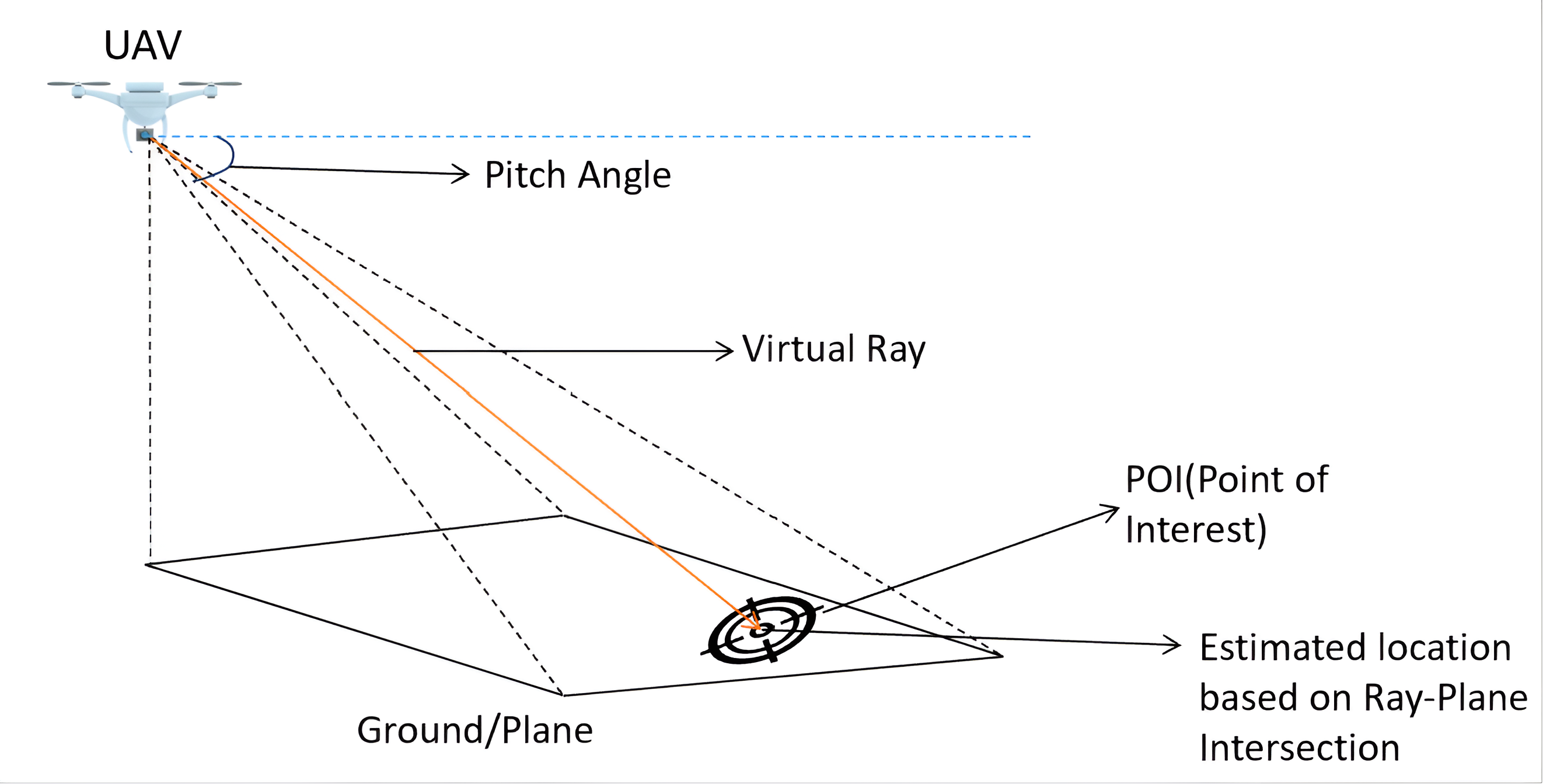
We employ the pinhole camera model to calculate the intersection of a UAV camera’s line of sight with the Earth’s surface. We treat the UAV’s camera as a pinhole camera, with each image sensor pixel representing a unique line of sight in 3D space. When a POI is identified by RO and selected in the aerial video stream, we project a directed ray from the camera through the identified pixel. The intersection point of this ray with the Earth’s surface determines the POI’s geolocation. During our calculation, we utilize the standard WGS-84 to calculate geographical positions of POIs in terms of latitude, longitude, and elevation above the ellipsoid of Earth. Figure 2 illustrates the application of pinhole camera model to compute the geolocation of POI visible in aerial video frame.
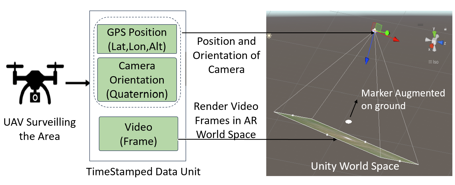
AR Marker Augmentation in Aerial Video A critical aspect of RO-AR is the real-time placement and augmentation of POI markers in the aerial video frame. These POI markers are positioned in the AR World Space of RO-AR based on their geolocation data (computed as discussed before), and placed at ground level (zero meters altitude). The precision of UAV camera’s movement in AR World Space depends on accurately interpreting data received from the UAV; GPS coordinates (latitude, longitude, altitude), and camera orientation data in Quaternions. GPS data from UAVs are converted into Unity’s local coordinate system in real-time to position the virtual camera precisely in AR space, mimicking the UAV’s real-world movements. The virtual camera’s orientation is adjusted using Quaternion values to align with the UAV camera’s perspective on the ground at each time step. Additionally, virtual camera properties such as lens focal length and field of view are configured to match those of the real UAV camera. As the AR camera moves and navigates through the AR environment guided by the UAV’s movements these POI markers become visible in the video feed when they enter the virtual camera’s field of view. The AR World Space illustrating this augmentation is shown in Figure 3, which shows the AR camera’s field of view rendering the aerial video frames as well as a POI marker (as overlay) within this view.
III-B OSO-AR
OSO-AR is a Location-Based AR system for on-site officers or OSOs with two important goals. First, to establish a bi-directional visual communication channel between OSOs and ROs, enabling OSOs to share their mission progress with ROs. Second, to visualize geolocated Points of Interest using Microsoft HoloLens 2, supporting situational awareness and decision-making.
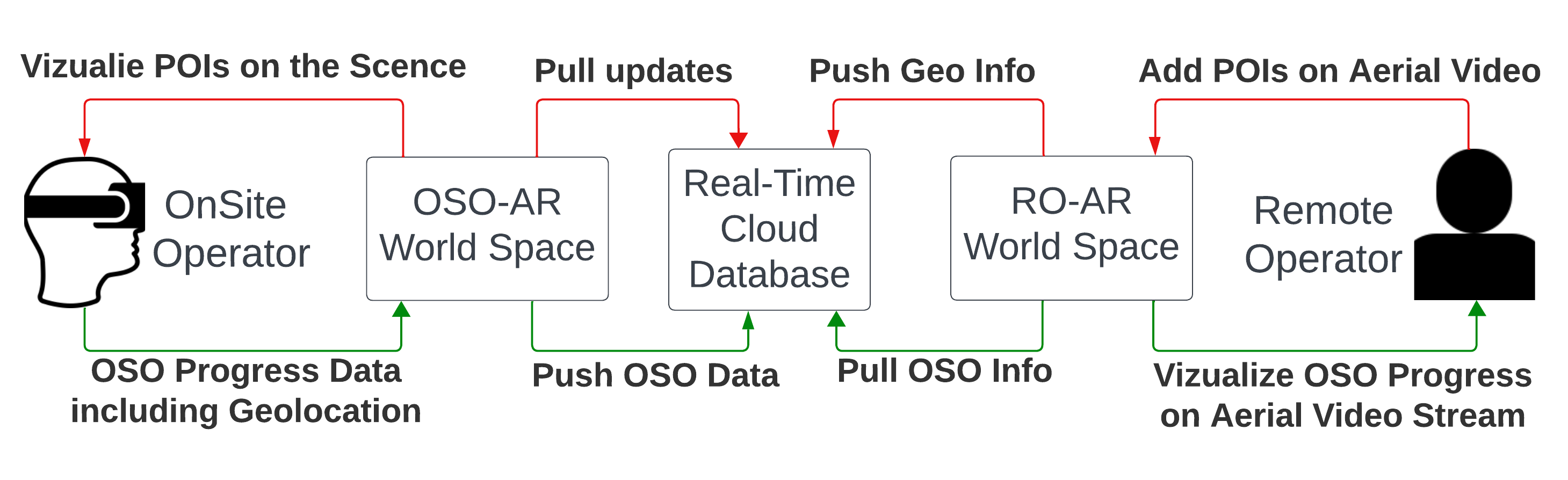
Bidirectional Information Sharing: OSO-AR is a Unity based application and creates its own AR world space where its AR camera replicates the real-world position and settings of the OSO’s headset. POIs are added in OSO-AR’s world space through VizCom-AR ’s cloud database over Wi-Fi. When an RO using RO-AR adds a POI, the geolocation of the POI and its metadata such as type of POI are recorded in VizCom-AR’s database. To keep OSO-AR’s AR World updated with POIs, OSO-AR fetches data from this database every 5 seconds. Also, OSO-AR shares data like the OSO’s location with RO-AR through the database, helping the RO track the mission. Figure 4 illustrates the bidirectional data flow between OSO-AR and RO-AR .
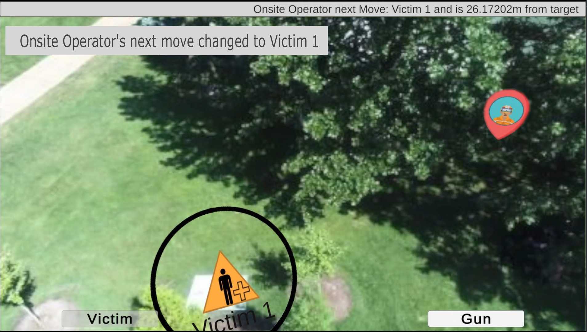
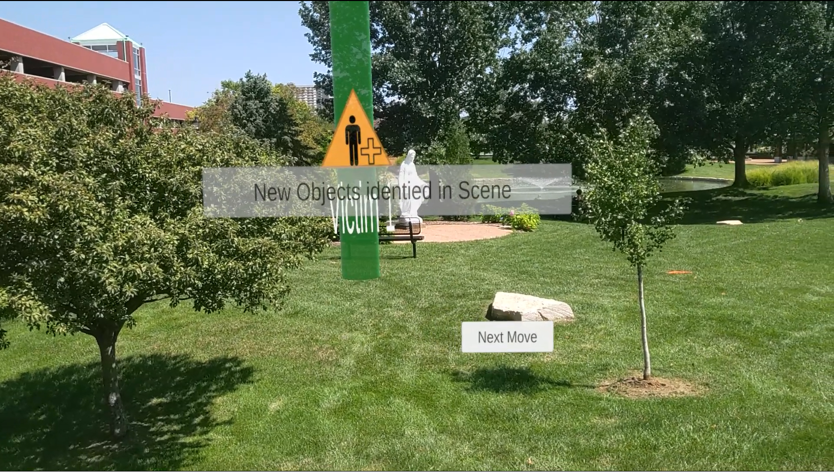
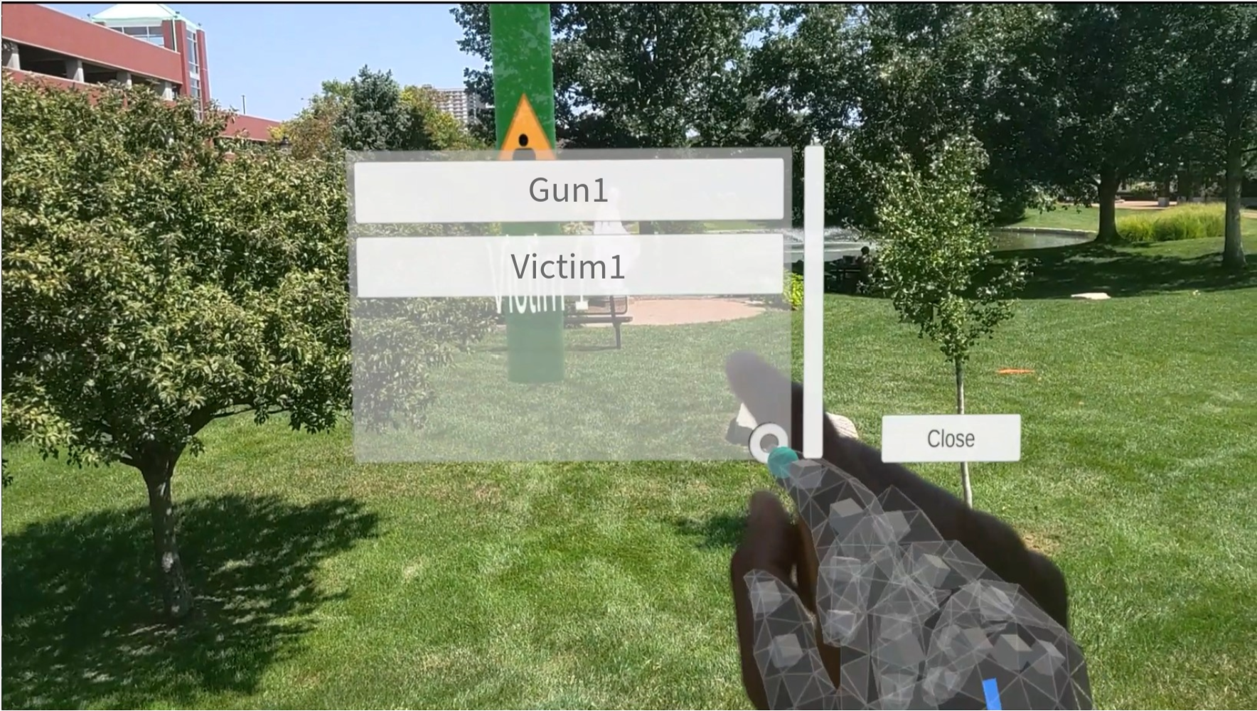
POI Visualization: In the OSO-AR system, POIs are visualized as 5-meter-tall virtual cylinders in the AR space, with an icon and label (indicating the POI type, like ’victim’ or ’evidence’) positioned 2 meters above the ground as shown in Figure 5(b). These cylinders automatically increase in height by 0.02 meters for every meter beyond 10 meters from the OSO, ensuring visibility in crowded or distant areas. The labels and icons are designed to rotate towards the OSO for improved visibility. For mission progress updates, OSO-AR includes an AR panel that allows OSOs to inform the RO about their mission status and select their next POI for investigation as shown in Figure 5(c).
IV Preliminary Discussion with Police Officers
We conducted a focus group session to gather feedback from the end-users of VizCom-AR on the conceptual design. Invitations to the focus group were sent via emails and resulted in the participation of five police officers (four males and one female). The participating officers were highly experienced in investigating incidents, with experience ranging from 15 to 40 years. Table I shows the participant’s backgrounds. Participants of the focus group were asked to discuss openly their past experiences of using UAVs, and opinions about VizCom-AR.
| Id | Current Designation | Years of Service |
|---|---|---|
| P1 | Police Chief | 17 |
| P2 | Deputy Chief of Police | 27 |
| P3 | Assistant Police Chief | 40 |
| P4 | Special Events Program Manager | 15 |
| P5 | Deputy Chief Safety Services | 34 |
In the first half of the session, we discussed UAV applications in emergency response, including river search and rescue, fire surveillance, and city surveillance, supported by real-world examples from news articles. We then explored participants’ current communication practices and challenges during emergencies. In the second half of the session, we presented the design of VizCom-AR using images and videos showcasing OSO-AR and RO-AR in operation. We encouraged discussion to understand their perspectives on the system’s potential applications and took notes for analysis.
IV-A Insights Gained from Focus Group Session
During the session, the police officers confirmed our previous understanding that they communicated primarily verbally via radio. Most participants agreed that radio communication suffers from excessive chatter and that superfluous information is frequently broadcast when multiple people talk or communicate simultaneously. Moreover, P5 pointed out that, in large-scale operations, this can create a chaotic situation, resulting in confusion among rescue personnel. P1 also stated that radio communications between dispatchers and callers can be frustrating due to the time-sensitive nature of the situation.
While discussing how geolocation information is communicated over the radio and how police officers interpret it, we learned that officers frequently refer to landmarks, roads, buildings, and other known entities in their environment. In this context, P1 shared that it can be difficult to identify locations when several buildings have similar names or textures. Police Officers’ current communication infrastructure lacked the capability to visualize information in any form. Finally, police officers reported that geolocation assists them in many ways – for example, by narrowing down their search or containment areas. They also agreed that tracking down a suspect becomes easier if the suspect’s past geolocations are known. Overall, during the discussion, police officers provided positive feedback on VizCom-AR to alleviate communication challenges, validating the design of VizCom-AR.
IV-B VizCom-AR Evaluation Goals
After receiving positive feedback from police officers, we proceeded with the system’s development and conducted a formal analysis of its effectiveness during search and rescue operations. Our primary goal was to evaluate VizCom-AR in real-world scenarios aimed at addressing the following research questions:
RQ1: How does the geolocation computation and marker augmentation of RO-AR vary across diverse flight characteristics, such as altitude and camera pitch angles?
RQ2: How does the overall design of VizCom-AR system compare to radio communication when communicating critical scene information?
V RQ1 - Experiments and Analysis
V-A Data Collection
We performed multiple carefully planned drone flights to collect video data that captures a POI in the scene. We also carefully placed a small whiteboard in an open field, marking it as our main POI for evaluation purpose. We accurately recorded its geo-location and also cross-verified this location manually using Google Maps. This thorough approach ensured a robust ground truth for our study.
Throughout the data collection process, we controlled the key variables of UAV to capture POI in the frame from various angles, heights, and distances. We collected aerial videos from three varying heights: 10 meters, 20 meters, and 30 meters; the latter being approximately 98 feet, which is the safe maximum allowed flight altitude in the area. We chose these heights to give us a range of views, from close up to a moderate distance above the ground. In addition to adjusting the height, we also changed the pitch angle of the UAV to four different angles: 45, 60, 75, and 90 degrees (Perpendicular to the ground). Each angle gave us a different way of looking at the POI.
V-B Geo-location Computation Analysis Method
In order to answer RQ1, we computed the (a) horizontal distance between the actual location of a POI in the real world and the computed location by our system and (b) the pixel distance between the AR marker and actual POI as visible in the aerial video stream. We utilized RO-AR to compute the geolocation of the POI as seen in the collected videos. During the analysis process, our objective was to precisely click at the center of the POI visible in the video frames. Since the analysis based on manual clicks could be compromised by the precision of the click itself, we automated the process of clicking on the POI and recording its pixel coordinates. As a result, from each video, we selected ten frames in which the whiteboard (POI) was visible and located at different parts of the frame. For each frame, we applied a common image processing technique known as contour detection using openCV [14] to identify the region of the screen occupied by POI and recorded the pixel coordinate of the POI’s center on the frame. These pixel coordinates of POI and the frame metadata are then used to calculate the location of POI as discussed in Section III-A. The geolocation computed by this method is then compared with the actual ground truth geolocation of the POI.
V-C Analysis - Geo-location Computation Accuracy
The geodesic distance between the calculated location and the ground truth location of POI across different Altitudes and Pitch Angles are shown in Figure 6.
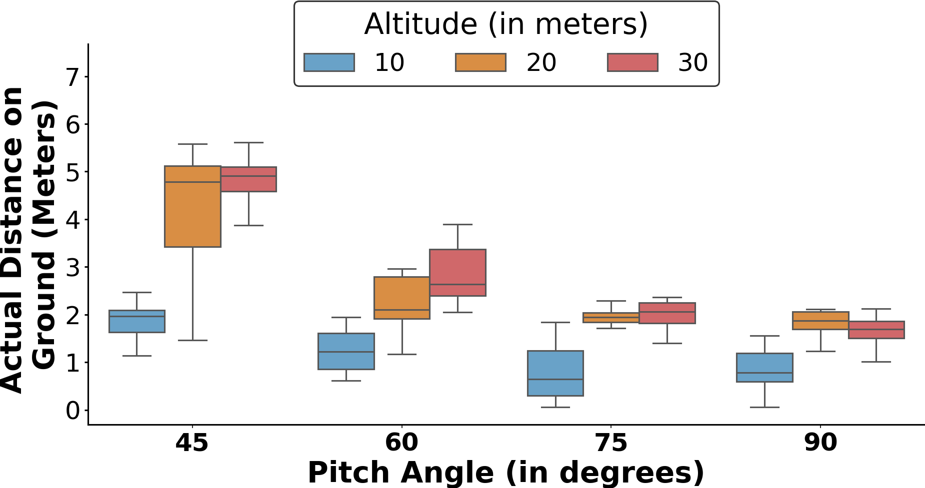
Figure 6 illustrates a decrease in horizontal accuracy (distance between computed and actual geolocation) with an increase in the altitude of the UAV. Specifically, the mean accuracy at altitudes of 10m, 20m, and 30m were recorded as 1.3 meters, 2.5 meters, and 2.9 meters, respectively. This pattern is largely due to the decreased spatial resolution in the imagery captured by the UAV at elevated altitudes, where each pixel represents a broader area of the ground. Thus, when trying to locate a POI in a high-altitude UAV’s aerial video stream on the screen, even a small pixel deviation can significantly increase the geolocation computation error.
Figure 6 also shows that the accuracy of the computed geolocation decreases as the camera’s pitch angle becomes more acute, meaning as the camera moves away from a position perpendicular to the ground. The highest accuracy is achieved when the camera is directly facing the ground (perpendicular). The mean accuracy at pitch angles of 45°, 60°, 75°, and 90° are 3.6m, 2.2m, 1.8m, and 1.5m, respectively. When the camera’s pitch angle moves away from perpendicular, each pixel in the video covers a larger ground area, making it essential to account for depth information to compute accurate geolocations. However, our current geolocation method does not factor in depth, leading to increased errors as the camera pitch becomes more acute.
V-D AR Marker Visual Accuracy Analysis Method
We designed our method to measure the pixel distance between the center of the AR marker appearing on the aerial video frame and the actual center of the POI in the same frame. First, we hard-coded an AR marker at the POI’s ground truth geolocation in the AR world space of the drone AR system. This ensures that the marker would automatically appear as an overlay on the aerial video whenever the UAV’s camera view captures the corresponding geolocation space, as discussed in Section 3. Secondly, we employed the same contour detection image processing technique to identify the centers of both the AR marker and the POI visible in the frame. We subsequently calculated the distance between the two central points and analyzed the Euclidean distance between these midpoints. During our analysis, whenever the POI and the augmented marker overlap in the frame, we consider the pixel distance to be zero, suggesting an accurate representation of the POI from the user’s perspective. From our collection of aerial videos, we selected the same 10 frames that we selected for analyzing the geolocation computation accuracy.
V-E Analysis - AR Marker Visual Accuracy
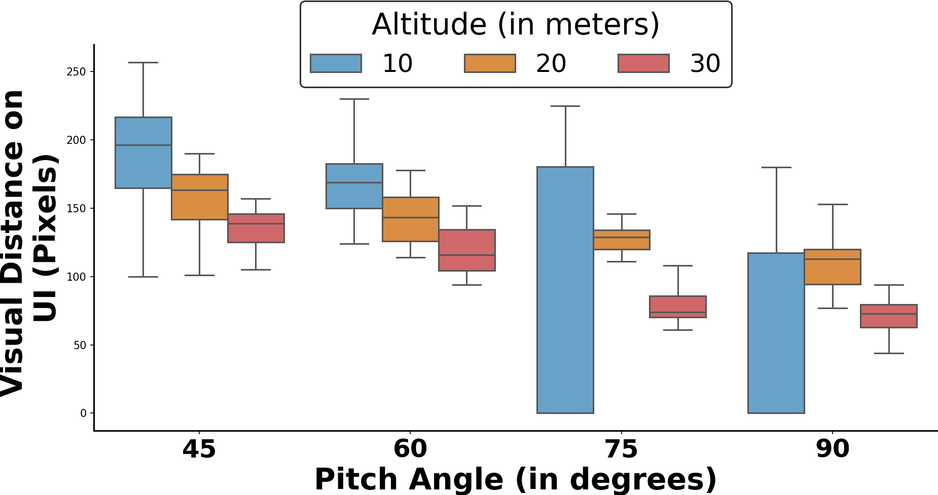
Figure 7 shows the distribution of pixel distance between the augmented marker and POI across various altitudes. First, at an altitude of 10 meters, we notice a high variance in pixel distance. This variance can be attributed to two reasons. First, at such lower altitudes, since the AR camera is closer to the ground, the actual distance (in meters) between two points on the screen is high compared to higher UAV altitudes, meaning that even minor differences between the computed and actual geolocations of the POI result in a higher pixel distance between the AR marker and the center of the POI on the screen. Second, we considered a pixel distance of 0 if an AR marker overlaps partially or completely with the actual POI. As a result, in cases when the geolocations are calculated precisely at lower altitudes (refer Figure 6) the pixel distance metric remains zero.
Figure 7 also shows that as the camera pitch angle deviates from a perpendicular position to the ground (pitch angle approaches 45 degrees), the pixel distance increases. This increase occurs because the computational accuracy of the POI diminishes as the camera pitch angles deviate from this perpendicular position, causing the appearance of AR markers on the screen to shift away from the POI.
VI RQ2 - Field Study and Analysis
We deployed our VizCom-AR in the real-world and conducted a field study to assess its performance in law enforcement activities and compared to traditional radio methods.
VI-A Field Setup
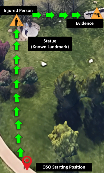
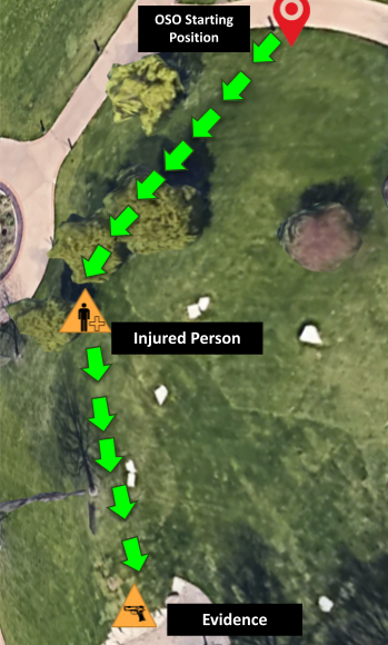
We recreated a search and rescue mission common to law enforcement officers in a controlled outdoor environment. Here, participants, acting as OSOs and ROs, collaborated to locate a victim and key evidence, represented by six-foot-long posters and a lookalike gun, within a predefined area. The ROs were responsible for overseeing the area via aerial footage from a pre-configured Parrot ANAFI Quadcopter UAV[15], identifying key POIs like the victim and evidence, and communicating their geolocations to the OSOs, whose task was to navigate the area and locate these POIs.To further mitigate biases in the search and rescue task, two distinct conditions were established: SR-KnownLandmark and SR-UnknownLandmark. In SR-KnownLandmark, the victim’s location was strategically placed near a unique statue (Refer to Figure 9), providing a clear reference point for communication. Conversely, in SR-UnknownLandmark, the communication challenge was increased by positioning the victim behind one of many trees (Refer to Figure 9). Additionally, to prevent the teams from relying on preconceived information, the position of the gun, representing key evidence, was varied between these two conditions. This approach ensures a more robust evaluation of the communication methods under different levels of complexity in the task environment.
VI-B Participants
In our initial field study, we engaged a total of 16 graduate students, organized into 8 teams comprising ROs and OSOs, with each task being performed by 8 teams across both conditions. The participant underwent thorough briefing and training to effectively perform the roles of ROs and OSOs. Tasks are assigned as follows:
RO Tasks: The RO’s main task involved using live aerial footage to locate key POIs like the victim and evidence and then relay their geolocations to the OSO.
OSO Tasks: The OSO’s task was to navigate the area, based on information provided by the RO, and locate the POIs.
Each participant was compensated $10 for their participation in a session that lasted approximately an hour. This initial field study allowed us to test the system in a real-world setting and prepared us for another study with police officers, which we plan to conduct in the near future.
VI-C Study Design
The study was structured into four phases. First, participants were briefed on VizCom-AR and Human-UAV interaction research, covering technology use and study objectives. The second phase involved training with the communication tools, including both radios and the VizCom-AR. The training session ensured that participants were familiar with and confident in using the RO-AR and OSO-AR systems before performing the actual study tasks. Following the training, the actual tasks were assigned to the teams, with specific roles designated to each member. To minimize biases, the initial communication system used for task completion, whether Radio or VizCom-AR, was counterbalanced across the teams. Each team executed the assigned task under both conditions. Further, to ensure robust and fair data collection, roles and field setups were switched before executing the task in the second condition. Finally, Upon completing the task in each condition, participants filled out a survey questionnaire.
VI-D Data Collection
During the study, we collected the GPS positions of OSO throughout the study to investigate the total distance traveled by OSO to complete the task. Additionally, we used a stopwatch to record the total time each team took to complete the assigned task. We also collected responses to our survey questionnaire to specifically gauge both OSO’s and RO’s Communication Quality.
VI-E Team Performance
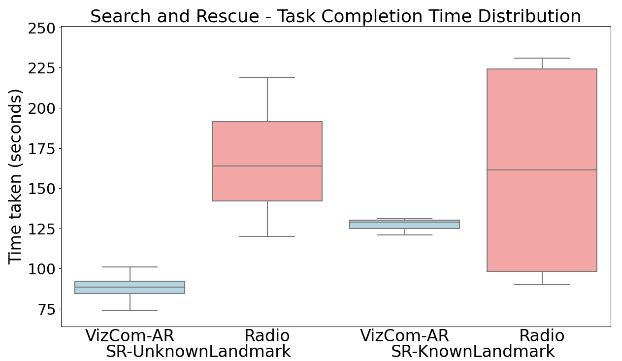
Figure 10 illustrates the distribution of time taken by teams to complete the search and rescue tasks using both Radios and VizCom-AR. Overall, participants demonstrated a more consistent and effective performance when using VizCom-AR as opposed to Radios. Teams using VizCom-AR showed improved median completion times with reduced variations when compared to Radio-based communication across the two conditions (SR-UnknownLandmark and SR-KnownLandmark). In the case of SR-UnknownLandmark, teams faced challenges in completing the task while using Radio-based communication(median time of 164 seconds, IQR 191–142 seconds) whereas teams that performed the same task using VizCom-AR showed significant improvement in task completion time(median time of 88 seconds, IQR 92–84 seconds).
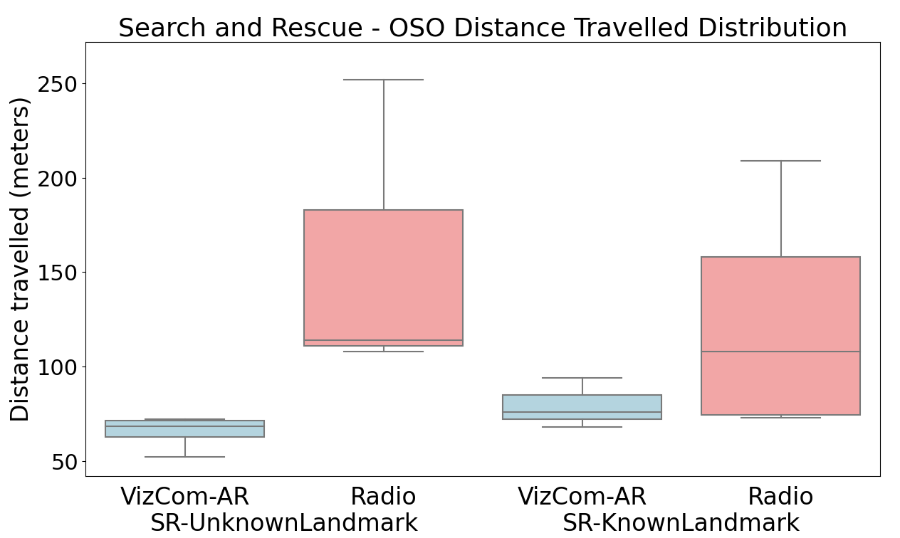
Similarly, in the SR-KnownLandmark condition, teams using VizCom-AR were more consistent, finishing the task in approximately 129 seconds (IQR 125-130 seconds). When using Radio, time varied; some teams used the landmark as the anchor to precisely communicate the location of the victim in the scene. This led to a wider spread of completion times, with a median of 161 seconds and an IQR of 98-224 seconds. Moreover, the substantial variations in time (as indicated by the wider inter-quartile range) reveal that individual differences in processing and communicating information over the radio played a role in the overall performance of the team. The total distance traveled by OSOs further reinforces these results. Utilizing Radio-based communication, OSOs were again able to minimize the distance traveled when the victim was near a unique landmark but faced challenges in scenarios with ambiguous environmental cues. With the use of VizCom-AR system, the distance traveled by OSO remained consistently shorter across both conditions, as shown in Figure 11.
VI-F Team Workload
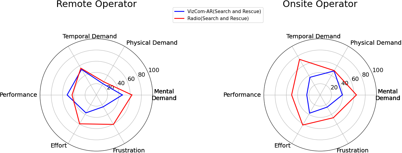
The NASA Task Load Index (TLX) results, as shown in Figure 12, provide evidence of VizCom-AR efficacy in alleviating the workload for both RO and OSO. Both RO and OSO experienced lower mental demand (score reduced from 63 to 46), frustration (score reduced from 60 to 24), and effort (score reduced from 59 to 36) when compared to using radio communication. On the other hand, while we expected improved perceived performance for both OSO and RO, participants felt they performed better with Radio than with VizCom-AR. This suggests that while VizCom-AR helped reduce the cognitive load for communicating geolocations and enhanced the RO’s experience, further research is needed to explore how training both RO and OSO can improve the effective use of Augmented Reality in their workflow for better performance.
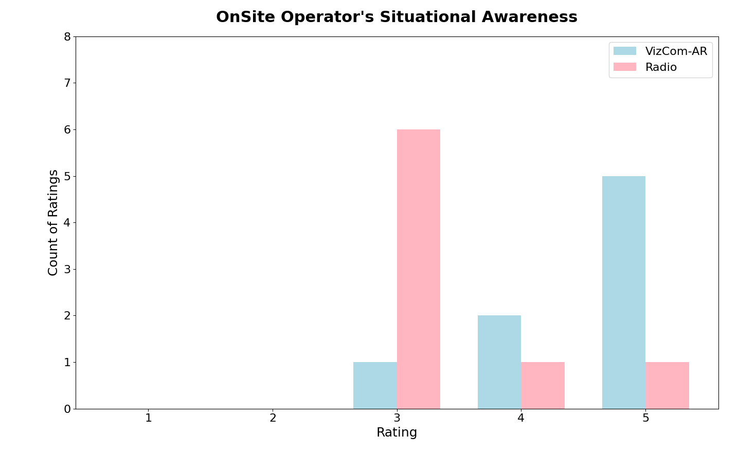
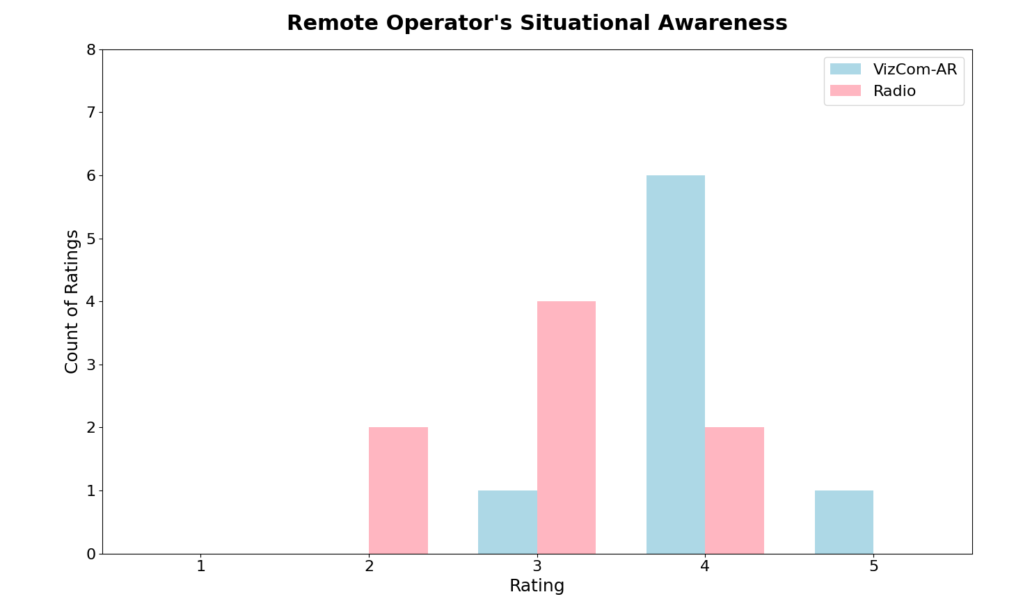
VI-G Situational Awareness
To gauge the situational awareness of both ROs and OSOs, we used a mixed-method approach that incorporated both a 5-point Likert scale and open-ended questions. The quantitative SA scores, illustrated in Figure 13 and Figure 14, show a substantial enhancement in SA when using VizCom-AR as opposed to traditional Radio-based Communication across all conditions. Notably, OSOs experienced a marked increase in SA when using VizCom-AR . Feedback from the open-ended questions complements these findings. OSOs specifically noted that VizCom-AR ’s visual cues made the identification of POIs straightforward, reducing the cognitive load, improving awareness, and aiding in task completion.
VII Conclusion and Future Work
We presented VizCom-AR that allows police officers or rescue mission personnel, including ROs who monitor the scene via aerial video streams, and OSOs who work at the scene, to communicate crucial geo-location information in complex environments precisely through Augmented Reality. Police officers validated the design and usability of the system in a preliminary focus-group session. We evaluated our system’s effectiveness under various UAV flight parameters, including changes in altitude and pitch angle. Furthermore, through a user study, we discovered advantages of using our system over traditional radio communication methods in emergency scenarios. Participants using our system completed tasks with greater efficiency and reported significantly improved situational awareness. This work opens up new research avenues, especially for the study of augmented reality technology to design complementary tools for data visualization and communication during UAV-driven search-and-rescue missions. The findings and lessons learned from this study provide a foundation for future advancements in the domain of AR-enhanced UAV-driven emergency response. In future, we aim to scale VizCom-AR to support multi-UAV missions. This enhancement would allow annotations from one aerial video stream to be automatically shared with other ROs monitoring different UAVs.
VIII Acknowledgement
We thank the Saint Louis University Research Institute for funding this work and Dr. Jane Cleland-Huang for moderating the focus group session and initial discussions during the conception of this project.
References
- [1] A. Agrawal, S. J. Abraham, B. Burger, C. Christine, L. Fraser, J. M. Hoeksema, S. Hwang, E. Travnik, S. Kumar, W. Scheirer, et al. The next generation of human-drone partnerships: Co-designing an emergency response system. In Proceedings of the 2020 CHI Conference on Human Factors in Computing Systems, pages 1–13, 2020.
- [2] A. Boateng, W. Zhang, and Y. Zhang. Implicit projection: Improving team situation awareness for tacit human-robot interaction via virtual shadows. In 2023 IEEE/RSJ International Conference on Intelligent Robots and Systems (IROS), pages 7945–7952, 2023.
- [3] A. Campos, N. Correia, T. Romão, I. Nunes, and M. Simões-Marques. Mobile augmented reality techniques for emergency response. In Proceedings of the 16th EAI International Conference on Mobile and Ubiquitous Systems: Computing, Networking and Services, pages 31–39, 2019.
- [4] J. Cleland-Huang and A. Agrawal. Human-drone interactions with semi-autonomous cohorts of collaborating drones. arXiv preprint arXiv:2010.04101, 2020.
- [5] D. E. Crowley, R. R. Murphy, A. McNamara, T. D. McLaughlin, and B. A. Duncan. Ar browser for points of interest in disaster response in uav imagery. In CHI’14 Extended Abstracts on Human Factors in Computing Systems, pages 2173–2178. ACM Press, 2014.
- [6] O. Erat, W. A. Isop, D. Kalkofen, and D. Schmalstieg. Drone-augmented human vision: Exocentric control for drones exploring hidden areas. IEEE transactions on visualization and computer graphics, 24(4):1437–1446, 2018.
- [7] H. Hedayati, M. Walker, and D. Szafir. Improving collocated robot teleoperation with augmented reality. In Proceedings of the 2018 ACM/IEEE International Conference on Human-Robot Interaction, pages 78–86, 2018.
- [8] N. Jayapandian. Cloud enabled smart firefighting drone using internet of things. In 2019 International Conference on Smart Systems and Inventive Technology (ICSSIT), pages 1079–1083. IEEE, 2019.
- [9] A. Khan, E. Yanmaz, and B. Rinner. Information merging in multi-uav cooperative search. In 2014 IEEE international conference on robotics and automation (ICRA), pages 3122–3129. IEEE, 2014.
- [10] N. Li, S. Cartwright, A. Shekhar Nittala, E. Sharlin, and M. Costa Sousa. Flying frustum: A spatial interface for enhancing human-uav awareness. In Proceedings of the 3rd International Conference on Human-Agent Interaction, pages 27–31, 2015.
- [11] C. Liu and S. Shen. An augmented reality interaction interface for autonomous drone. In 2020 IEEE/RSJ International Conference on Intelligent Robots and Systems (IROS), pages 11419–11424, 2020.
- [12] B. S. Manoj and A. H. Baker. Communication challenges in emergency response. Communications of the ACM, 50(3):51–53, 2007.
- [13] I. L. Nunes, R. Lucas, M. Simões-Marques, and N. Correia. An augmented reality application to support deployed emergency teams. In Congress of the International Ergonomics Association, pages 195–204. Springer, 2018.
- [14] OpenCV. Open source computer vision library, 2015.
- [15] Parrot. Parrot anafi — compact and resistant drone with a 4k hdr camera. https://www.parrot.com/us/drones/anafi. (Accessed on 06/10/2022).
- [16] J. R. Paterson, J. Han, T. Cheng, P. H. Laker, D. L. McPherson, J. Menke, and A. Y. Yang. Improving usability, efficiency, and safety of uav path planning through a virtual reality interface. In Symposium on Spatial User Interaction, pages 1–2, 2019.
- [17] C. Pittman and J. J. LaViola Jr. Exploring head tracked head mounted displays for first person robot teleoperation. In Proceedings of the 19th international conference on Intelligent User Interfaces, pages 323–328, 2014.
- [18] J. D. Stevenson, S. O’Young, and L. Rolland. Beyond line of sight control of small unmanned aerial vehicles using a synthetic environment to augment first person video. Procedia Manufacturing, 3:960–967, 2015.
- [19] M. Sun, N. Dong, C. Jiang, X. Ren, and L. Liu. Real-time muav video augmentation with geo-information for remote monitoring. In 2013 Fifth International Conference on Geo-Information Technologies for Natural Disaster Management, pages 114–118. IEEE, 2013.
- [20] R. Suzuki, A. Karim, T. Xia, H. Hedayati, and N. Marquardt. Augmented reality and robotics: A survey and taxonomy for ar-enhanced human-robot interaction and robotic interfaces. In Proceedings of the 2022 CHI Conference on Human Factors in Computing Systems, pages 1–33, 2022.
- [21] T. Verge. Dji drones helped track and stop the notre dame fire - the verge. https://bit.ly/drones-in-firefighting. (Accessed on 10/15/2024).
- [22] M. Walker, H. Hedayati, J. Lee, and D. Szafir. Communicating robot motion intent with augmented reality. In Proceedings of the 2018 ACM/IEEE International Conference on Human-Robot Interaction, pages 316–324, 2018.