Development and commissioning of a new readout system for the gas flow of the Belle II and muon detector
November 6, 2024
Abstract
We have designed and commissioned a new readout board to detect photosensor signals from gas-bubbler panels to continuously monitor the gas flow through the resistive plate chambers of the and muon detector of Belle II. The gas flow measurements have been integrated into Belle II’s alarm system. The bubbler-monitoring system was first employed during the February 2024 to July 2024 Belle II data-taking period.
keywords:
detector , RPC , monitoring , signal processingcomment \RenewEnvironcomment\BODY
[1]organization=Iowa State University, city=Ames, country=USA \affiliation[2]organization=Virginia Tech, city=Blacksburg, country=USA \affiliation[3]organization=High Energy Accelerator Research Organization, city=Tsukuba, country=Japan
1 Introduction
The and muon subdetector (KLM) of the Belle II B-Factory experiment [1] operating at the SuperKEKB collider identifies copiously produced mesons and muons, which are useful for studying precision Standard Model and beyond the Standard Model physics. The KLM is composed of three sections: a barrel and two endcaps. The barrel has a forward section facing the higher-momentum electron beam and a backward section facing the positron beam. Each barrel section has an octagonal structure subdivided symmetrically into eight sectors. In the barrel, the detector panels of the outer 13 layers are composed of glass-electrode resistive plate chambers (RPCs) [2], while the inner two layers are composed of scintillating strips. Each RPC panel is composed of an inner and outer RPC, which are independently operated. Each RPC in the panel has two parallel sheets of float glass for electrodes, separated by noryl spacers, epoxied in place. All layers in the endcaps use scintillating strips. Three-dimensional measurements of a particle’s position are obtained from hits on orthogonal readout strips in each layer. The RPCs, including gas-flow measuring bubblers, were installed in the Belle detector [3], Belle II’s predecessor, and were used from 1999 to 2011. The bubbler readout system, however, was not included in the initial upgrade to Belle II.
It was discovered in April 2021 that a sector’s RPC gas flow regulator had been accidentally switched off, and the affected RPCs had gone without gas flow for two years. Further investigations showed that one of the sixteen KLM barrel half-octants experienced a 50% reduction in hit detection efficiency. The suspected culprit is moisture accumulation in the RPC gas.
To prevent another case of detector damage and detection efficiency loss, we have developed and installed a new readout and monitoring board that uses the existing Belle-era bubbler hardware. We continuously monitor KLM RPC gas flow by measuring the exhaust-line gas bubble rates, which is parsed by the readout board from analog signals received from the bubblers. The bubbler-monitoring system is integrated into the Belle II alarm and archival system.
Here, we discuss the development and commissioning of the new readout board, which is composed of analog multiplexers, analog-to-digital converters, and a single board computer, to process the analog signals from the existing Belle-era bubbler panel readout boards.
2 Measuring the RPC gas flow
2.1 Bubbler panels
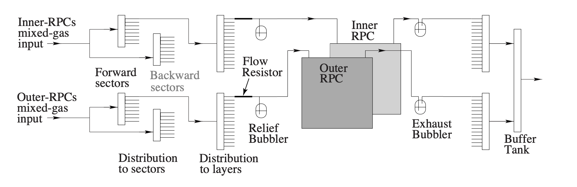
The RPCs in the barrel KLM operate with a gas mixture of HFC-134a, argon, and butane-silver. During normal beam operation, the nominal flow rate is 2 L/min. Fig. 1 shows the RPC gas-distribution system, which consists of injecting the RPC gas mixture into distributors that direct the gas through the individual RPCs. Between a distributor and each layer’s RPC, there is a relief bubbler through which the gas can vent if there is overpressure. After passing through the RPC, the gas flows through an exhaust bubbler and into a buffer tank. The gas flow-rate through each RPC can be monitored by measuring the bubble rate in its exhaust bubblers.
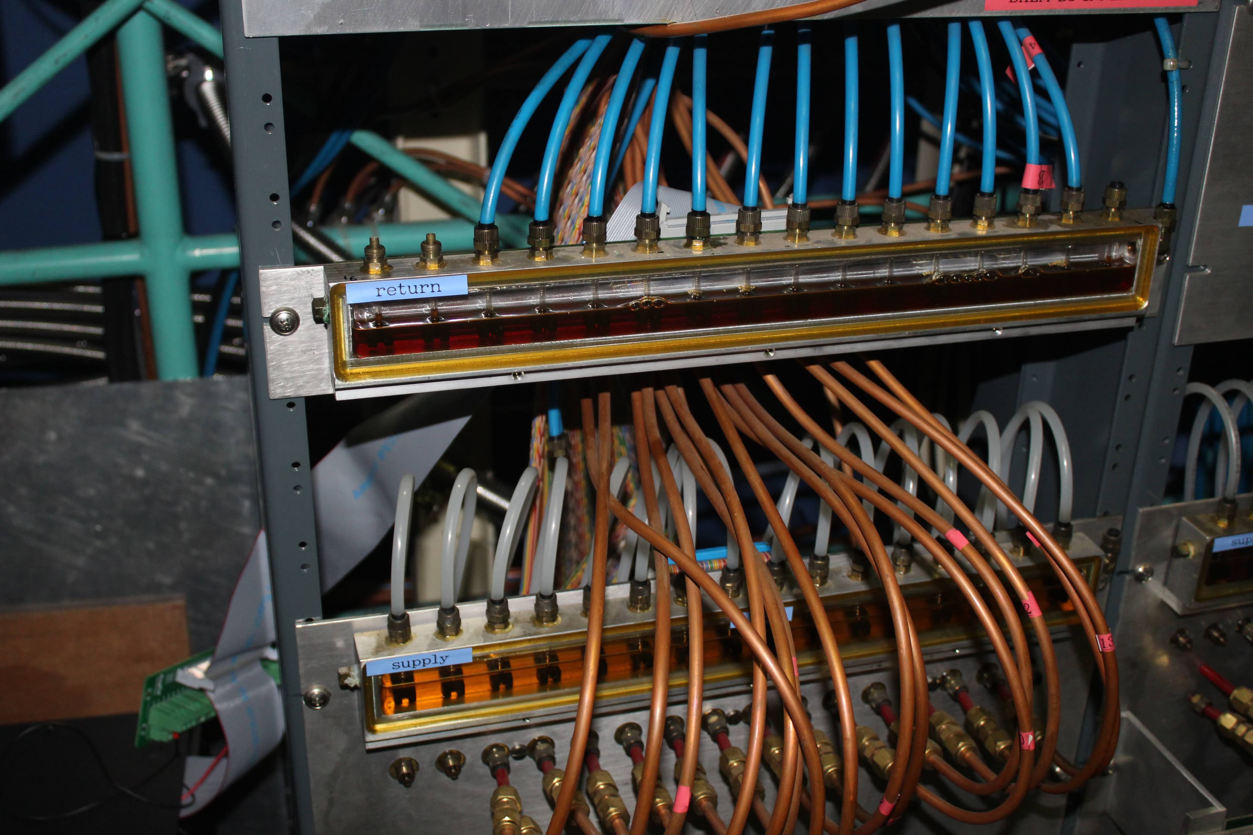
During normal operation, bubbles are expected in the exhaust bubblers but not relief bubblers. Flow in a relief bubbler indicates an overpressure condition in the RPC that may damage the RPCs. The exhaust and relief bubblers for a KLM sector are assembled on rack-mounted panels (see Fig. 2).
Each bubbler comprises an open-ended tube for gas flow, an infrared LED, and a photosensor. The cavity that the gas flows into is partially filled with mineral oil. When the gas exits the tube into the oil, it creates a bubble. The bubble refracts light from the LED, creating an analog signal in the photosensor. The analog signals for the 13 bubblers for each sector are collected by a circuit that was deployed in the Belle era. The circuit collects the analog signals and transmits them via a ribbon cable connector to our new readout boards. (The Belle bubbler-readout system was not used by Belle II.) In total, there are 832 bubbler rates to measure in the Belle II KLM gas system: (1 exhaust + 1 relief) bubblers 2 orthogonal-strips 13 layers 8 octants 2 forward/backward sections.
2.2 Bubble rate measurement
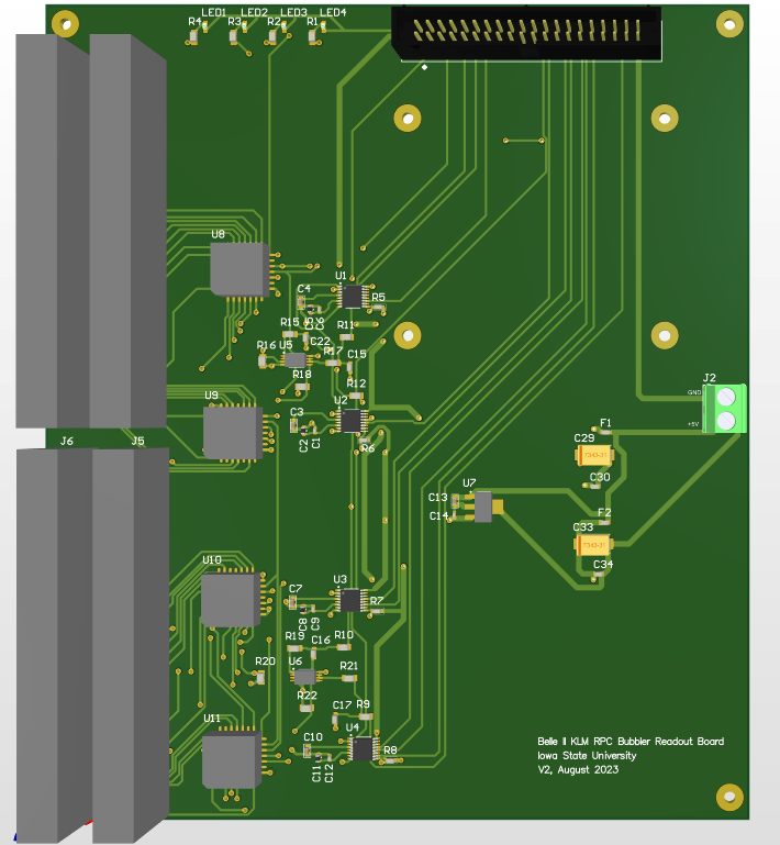
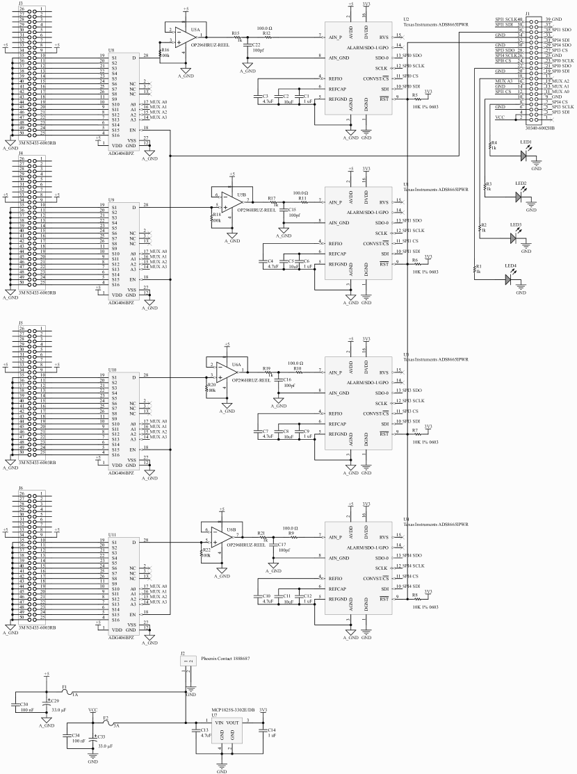
The analog signals from the photosensors are routed via ribbon cable to a newly designed printed circuit board. We have designed the board to process analog signals from up to 4 16 channels (see Fig. 3). The analog signals first pass through the board’s 16-channel multiplexer, the ADG406. Next, the signals are digitized by the board’s 12-bit Analog-to-Digital Converter (ADC), the ADS8665. Each board has four ADCs to accommodate an entire sector consisting of exhaust and relief bubblers for each of the two layers of 13 RPCs. The digital output from the ADCs is communicated to a board-mounted single-board computer (SBC), a Raspberry Pi 4 Model B, using the Serial Peripheral Interface protocol via the SBC’s input/output pins. The SBC also controls the multiplexer switches. One entire process cycle, which consists of switching through 16 channels and for each channel collecting the digital output for each of the four ADCs, takes 2.4 milliseconds. The system can collect 250,000 sensor readings over a period of 10 minutes for each of the 4 ADCs 16 channels/ADC = 64 channels. A single bubble has a duration of 150-250 milliseconds and is accurately resolved with approximately 60 readings.
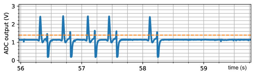
A bubble’s passage in front of an LED refracts the light away from the photosensor, creating a characteristic voltage pulse (see Fig. 4). The software on the SBC can distinguish the signal pulses from the otherwise constant voltage. The signal-recognition software triggers on a rising edge of a pulse through a voltage threshold as well as a minimum bubble width threshold to avoid double-counting. Typical bubbling rates for exhaust bubblers are Hz.
Each board processes analog signals from 4 ribbon cables 13 channels = 52 channels using four multiplexers, four ADCs, and one SBC. We have packaged four boards into a crate together with a power supply and an Ethernet switch. The power supply in the crate is powered by a network-connected 110 V Power Distribution Unit, which allows for remote power cycling. In total, we have built four crates containing four boards each.
3 Integration with Belle II
3.1 Network communication
Each crate is connected via Ethernet to the Belle II data acquisition network, Network Shared Memory (b2nsm) [4], which enables network communication with the SBCs through the crate’s Ethernet switch. Bubble rates are recorded and stored by Belle II’s EPICS-based archiving system [5]. Real-time bubble rates are communicated as EPICS Process Variables (PVs) via b2nsm to operators in the Belle II control room. Abnormal flow rates trigger an alarm.
3.2 Alarm configuration
Each bubble rate PV has an associated alarm status, which is integrated into the Belle II detector control and alarm system [6]. The alarm criteria have been configured to be sensitive to interruptions in individual RPC bubbling rates that may result from broken or disconnected tubes. We have also configured the alarms to be sensitive to a gas regulator outage, which is characterized by a complete loss of bubbling rate in a sector’s exhaust bubblers, and may be accompanied by a nonzero bubbling rate in the associated relief bubblers. The time scale for triggering an alarm in response to a gas regulator outage is 30-50 minutes, and for triggering to broken tubes is 1-2 hours.
In the exhaust bubbler channels, where bubbles are expected during normal operation, an alarm is triggered if the bubbling rate falls outside a tunable range, defined by a specific number of standard deviations from the channel’s mean bubbling rate. In the relief bubbler channels, where bubbles are not expected during normal operation, an alarm is triggered if any bubbles are observed. The alarm configuration can be easily modified to be sensitive to other gas flow issues that may arise in the future.
Negligible damage is expected in the RPCs from gas flow interruptions on the time scale of less than a week. An alarm due to a low exhaust bubbling rate during beam operation will be addressed by checking for broken tubes or gas regulator problems on the next biweekly detector maintenance day. For detector safety, the high voltage supplied to these RPCs is turned off if there is no gas flow through the RPCs.
3.3 Monitoring GUI
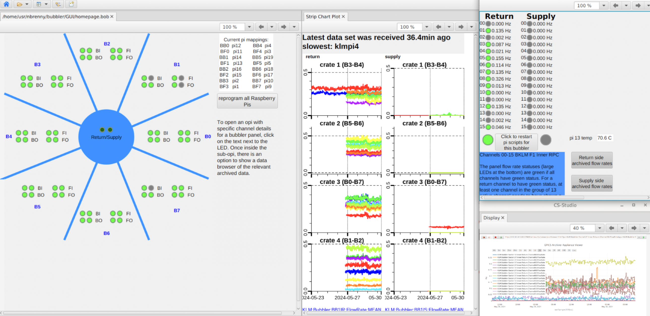
To visualize the status of the RPC gas flow, we have designed a Graphical User Interface (GUI) (see Fig. 5) to summarize the bubbling rates for each sector, which is available to the KLM operator during beam operations. The GUI is implemented using Control System Studio [7]. It consists of a summary panel with indicators that show the bubbling rate status of the 64 13-channel panels, as well as more detailed panels with real-time bubbling rates for the individual 13 channels for each bubbler panel. Also displayed in the GUI are the mean and standard deviation of the bubbling rates for each bubbler panel. The KLM operator can check the bubble rate history in the GUI for more thorough investigations. The GUI can also be used to reprogram the SBCs remotely.
4 Performance
We have tested the performance of the alarm configuration using bubbling rate data from previous gas flow issues. In December 2023, before the bubbler-monitoring system was completely commissioned, a gas regulator was accidentally unplugged. It resulted in no bubbles in the exhaust bubblers and bubbles in the relief bubblers. The alarm configuration correctly generated an alarm when presented with this failure-mode data, validating the configuration’s sensitivity to the gas regulator outage problem.
The bubbler-monitoring system was in use during the data-taking period from February 2024 to July 2024. During a maintenance day in this period, four gas tubes at a bubbler panel located in a heavy-traffic location were damaged by inadvertently jostling. The bubbler-monitoring system immediately discovered the decrease in flow. Experts were then notified, and the tubes were replaced. This situation demonstrated that the bubbler-monitoring system can detect interruptions in individual RPC gas flow rates. No gas regulator problems were observed the aforementioned data-taking period.
5 Summary
We have presented the hardware and software developments that constitute the integration of a new KLM RPC bubbler-monitoring system at Belle II. We have designed a readout and monitoring board consisting of analog multiplexers, ADCs, and an SBC to read analog bubble signals from the photosensors. Software on board the SBC recognizes the bubble signals, computes bubbling rates, and broadcasts the bubbling rates to the Belle II archiver. The bubbling rates have been integrated into the Belle II alarm system. The integrated bubbler-monitoring system is capable of detecting a gas regulator issue like the one that contributed to a 50% detection efficiency drop in one sector of the Belle II KLM in 2021. Furthermore, the bubbler-monitoring system is sensitive to gas flow outages of individual RPCs. Broken gas supply tubes have been discovered by the bubbler-monitoring system, and no gas regulator problems have been observed during this system’s commissioning operation in early 2024.
Acknowledgements
This work was supported by the U.S. Department of Energy and Research Award No.DE-SC0021430 and via U.S. Belle II Operations administered by Brookhaven National Laboratory (DE-SC0012704).
This acknowledgment is not to be interpreted as an endorsement of any statement made by our institute, funding agency, government, or its representatives.
References
- [1] T. Abe et al. (Belle II Collaboration), arXiv:1011.0352 .
- Abashian et al. [2000] A. Abashian et al. (Belle Collaboration), Nucl. Instrum. Meth. A 449, 112 (2000).
- Abashian et al. [2002] A. Abashian et al. (Belle Collaboration), Nucl. Instrum. Meth. A 479, 117 (2002).
- Nakao and Suzuki [2000] M. Nakao and S. Suzuki, Nuclear Science, IEEE Transactions on 47, 267 (2000).
- Kim et al. [2021] Y.-K. Kim, S.-J. Cho, S.-H. Park, M. Nakao, and T. Konno, IEEE Transactions on Nuclear Science 68 (2021), 10.1109/tns.2021.3084878.
- Kunigo et al. [2024] T. Kunigo et al., “Alarm and recovery system in the Belle II operation,” (2024), Poster presented at 24th IEEE Real Time Conference.
- Hatje et al. [2007] J. Hatje, M. Clausen, C. Gerke, M. Moeller, and H. Rickens, (2007), https://controlsystemstudio.org.