Bio-inspired reconfigurable stereo vision for robotics using omnidirectional cameras
Abstract
This work introduces a novel bio-inspired reconfigurable stereo vision system for robotics, leveraging omnidirectional cameras and a novel algorithm to achieve flexible visual capabilities. Inspired by the adaptive vision of various species, our visual system addresses traditional stereo vision limitations, i.e., immutable camera alignment with narrow fields of view, by introducing a reconfigurable stereo vision system to robotics. Our key innovations include the reconfigurable stereo vision strategy that allows dynamic camera alignment, a robust depth measurement system utilizing a nonrectified geometrical method combined with a deep neural network for feature matching, and a geometrical compensation technique to enhance visual accuracy. Implemented on a metamorphic robot, this vision system demonstrates its great adaptability to various scenarios by switching its configurations of 316° monocular with 79° binocular field for fast target seeking and 242° monocular with 150° binocular field for detailed close inspection.
I INTRODUCTION
Stereo vision techniques, enabling robots to perceive the world in three dimensions, have been pivotal in expanding the boundaries of robotic visual capabilities [1, 2]. From factory assembly lines to uncharted territories, stereo vision-equipped robots capable of accurate depth perception and enhanced spatial understanding undertake tasks with unprecedented exploration capacity and working precision [3, 4]. Binocular depth estimation is the primary method for obtaining spatial information in machine vision [5, 6]. The common practice involves positioning two cameras at different viewpoints using pin-hole camera models for depth information acquisition. To improve measuring accuracy and reliability, the binocular camera is often enhanced with infrared structured light or line laser, employing homologous point matching methods, including epipolar alignment and feature extraction[7, 8]. Present models and products such as Intel’s RealSense [9] and Microsoft’s Kinect [10] are frequently used as vision information sources for robots, which are widely applied in various robotic fields, such as mobile robots for navigation and field exploration [11], and service robots for object recognition and manipulation [12]. The hardware of existing stereo vision systems commonly consists of a pair of co-planar pin-hole cameras. However, this monotonous hardware with a limited field of view (FOV), 60-90° [13], confines the spatially visual performance in stereo vision systems for practical and versatile applicable scenarios.
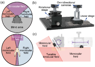
To address the problems mentioned above, we turn to nature for heuristics. Present robots with bio-inspired designs have exhibited profound impacts in various intrinsic structures and biomimetic motions, including quadruped running, entangled grasping, and continuous jumping [14, 15, 16]. Furthermore, the metamorphic design is inspired by the morphology variation and performance development during the growth process of typical species. Promising progress of the metamorphic design, such as various gaits of a quadruped robot realized by changing the relative position of the joint axis [17], swimming and crawling modes switching by tuning the limbs of the turtle robot [18], and different moving strategies of the transformable origami exoskeleton [19], has been made to enhance their locomotion characteristics and adapt to versatile environments and tasks. Most of the existing bio-inspired designs focus on their mechanical structures and ignore the abundant vision features. Herbivores, e.g., rabbits, possess a panoramic FOV (360°) but narrow binocular field (30°)[20]. In contrast, carnivores and omnivores, like cats, possess a confined FOV (186°) but a broad binocular field (98°) (Fig. 1(a))[21]. The differences in FOV among different species are due to the alignment of the eyes. Realizing a reconfigurable stereo vision system would benefit robots by enabling them to explore different scenarios with tunable vision features.
To achieve the proposed vision system, a vision workflow algorithm that matches the system’s requirements and features is necessary. Currently, common vision algorithms rely on the epipolar constraint and pin-hole camera assumption, which requires two cameras in a stereo vision system to be fixed on the same plane with the same imaging focal length and horizontally aligned [7, 8]. The current algorithmic limitation restricts the realignment of the cameras and confines the reconfigurability of the mainstream stereo vision systems. Furthermore, the tunable FOV envisaged with a reconfigurable physical platform also proposes a new challenge for the vision algorithm.
Therefore, a biomimetic reconfigurable stereo vision system is proposed that can tune the alignment of the two omnidirectional cameras to create different FOV and binocular fields through a reconfigurable platform (Fig. 1(b-c)). The vision workflow algorithm modifies the nonrectified geometrical method [22], which typically utilizes the retrieved optical path for depth measurement of the system to maintain the wide FOV. Additionally, a deep neural network [23] is employed to match local features reliably, and a geometrical compensation method is utilized to optimize and filter the results. This endows the system with the capability to collect stereo point clouds for multiple purposes, offering flexibility for a reconfigurable wide FOV vision system. Finally, the reconfigurable stereo vision system is deployed on a metamorphic robot, Origaker [24], providing this robot with various tunable vision features, including a large FOV for target-seeking and a large binocular field for detailed inspection, demonstrating the excellent adaptability for versatile applicable scenarios.
The main contributions of this article are as follows:
1. A reconfigurable stereo vision strategy was first proposed by tuning the alignment of the two installed omnidirectional cameras with a reconfigurable platform.
2. A depth measurement system for binocular vision was developed based on the improved nonrectified stereo method with a deep neural network feature matcher and a geometrical compensation method, enabling precise depth measurement for a non-planar camera alignment.
3. The reconfigurable stereo vision system was deployed on a metamorphic robot to realize a tunable vision characteristic, demonstrating a large FOV for target seeking and a large binocular field for detailed inspection.
II Vision algorithm of the reconfigurable vision
To obtain a biomimetic and wide FOV, two omnidirectional cameras are employed in our system. The conventional graphic process relies on methods like rectification and epipolar alignment, which typically results in a loss of both FOV and accuracy. Additionally, the technique is not applicable to reconfigurable design. Therefore, a geometric depth measurement approach [22] is utilized to maintain the edge region of omnidirectional images for depth measurement in non-planar camera settings. However, the native implementation of this method is constrained by precision limitations, with errors propagating from several aspects, such as extrinsic calibration and homologous point matching. While the point set acquired is feasible for navigation, it remains a challenge to use as a universal visual method. To address this problem, a neural network matching method is employed to obtain reliable homologous points in complex and challenging environments robustly, and a geometric compensation method is integrated to optimize and filter the calculated spatial points. This approach enables the system to acquire a higher quality set of spatial point information, thereby enhancing its potential to be used as a general visual method. All spatial information obtained from our vision system is from this non-rectification method, including the setup of the system.
II-A Optical Path Retrieve Model
Stereo depth measurement follows a general pipeline: find homologous points in the overlapped field of view of binocular cameras, retrieve the incident optical path that connects the camera center and the real-world point, and then triangulate to find the spatial location. Retrieving the incident optical path is straightforward for commonly used pin-hole camera models since the optical path is not reflected. However, for omnidirectional cameras, special camera models are needed to map the optical path due to the use of a significant amount of barrel distortion to compress a wide scene into a limited image area. In our approach, the commonly adopted Kannala-Brandt model (Fig. 2) is utilized to address the distortion of the omnidirectional lens[25].
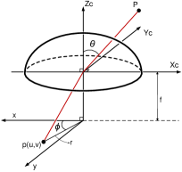
The image point of interest p(u, v) refers to the point where the incident ray passes spatial point P and projects onto the normalized image plane. f refers to the focal length, , the polar angle, refers to the angle between the principal axis and the incident ray, , the azimuthal angle, refers to the angle between the positive x-axis and the connection line of p(u,v) to the principal point. r is the distance of p(u,v) to the principal point. To identify this ray, two parameters, the polar angle and the azimuthal angle , are needed. From the Kannala-Brandt camera model, is known by:
| (1) |
here, , , , and are the distortion parameters from camera calibration, r is computed with the image processing result and the intrinsic parameters. In this case, the equation could be used to solve by numerically solving the polynomial.
The azimuthal angle is then computed by:
| (2) |
With the knowledge that the incident optical path passes through the origin of the camera frame (the principal point), the optical path of an image point of interest is now retrieved for the subsequent processes, including calibration and depth computation.
II-B Calibration
To perform stereo vision depth measurements, both the intrinsic and extrinsic parameters of both cameras are needed. For intrinsic calibration, each of the two omnidirectional cameras is calibrated separately using the Kannala-Brandt model with OpenCV’s built-in module [25, 26]. For extrinsic calibration, the conventional approach typically involves rectifying the omnidirectional image before performing extrinsic calibration using the usual pin-hole camera model approach. However, the existing methods prove ineffective in our setup due to the non-planar camera placement and the narrow overlapped vision, which is often located at the edge regions in certain visual modes and would be cropped in the rectification. Hence, a novel method is developed for extrinsic calibration of non-planarly placed omnidirectional cameras in our reconfigurable systems.
Using the chessboard calibration board, OpenCV’s built-in grid point detector is leveraged to accurately determine sub-pixel coordinates of the chessboard corners in the captured image. Each chessboard corner corresponds to a reverse incident optical path, which allows the system to identify a bundle of rays, each ray connecting the camera center with a grid point on the board. Utilizing the known distribution of the chessboard grid points, an optimization problem is formulated to identify a plane whose intersections with the ray bundle best fit the expected distribution. By solving this optimization problem, the 3D position of the chessboard corners could be precisely determined in the camera frame in one calibration picture.
Since our proposed method requires stereo vision overlap, the chessboard is positioned within the overlapping FOV of both cameras. This allows the system to determine the 3D spatial coordinates of the chessboard grid points in each camera frame with the optimizing solution above. A least-squares fitting method[27] is then applied to fit the relative pose between the two camera frames, minimizing the reprojection error. Using this approach, the extrinsic parameters of the cameras are acquired.
II-C Homologous Point Matching
In stereo vision systems, identifying homologous points across different camera views is crucial for depth estimation and 3D reconstruction. However, due to the flexible nature of our stereo vision setup, the system cannot rely on traditional epipolar constraints and feature-based methods to find these point pairs. Instead, an advanced deep neural network structure, LightGlue[23], is employed to achieve accurate and efficient feature matching. LightGlue provides a robust solution for challenging match cases such as large changes in view angle, small visual overlaps, and challenging lighting environments with precision and efficiency, which meets the needs of our system.
II-D Depth Computation Through Pseudo Intersection of Retrieved Optical Paths
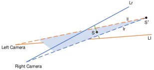
The spatial location of the homologous point is calculated by triangulation of the retrieved optical path and extrinsic parameters of the camera set. Ideally, these physical points lie at the intersection of the respective optical paths on the intersection plane (determined by the two camera frame origins and the ideal optical path intersection). However, in practice, due to matching errors and image degeneration throughout the hardware and workflow, it is mathematically challenging for two optical paths to intersect precisely. To address this issue, a geometric correction mechanism is introduced that projects the two optical paths onto a predicted intersection plane to find a pseudo intersection to represent the spatial location of the homologous point (Fig. 3). The predicted intersection plane is determined by the origins of the two camera frames and the midpoint of the shortest distance between the two optical paths[28]. S is the midpoint between the two optical paths, Ll and Lr. The two projected optical paths, ll and lr intersect on the predicted plane to form the pseudo intersection S’.
This proposed pseudo intersection correction method, showing its great monotonicity against different matching errors, has presented its advantages in both error minimizing and error filtering. To minimize errors, finding the proposed pseudo intersection provides a more precise and robust guess for noisy or mismatched inputs.
Currently, in the workflow, the main error source results from the mismatch of the homologous points, which is a common and inevitable event in the vision pipeline. The mismatched point pairs are divided into 3 zones, the slightly mismatched zones are defined for pairs where the resulting overall x-y plane error on the normalized directional vector of the corresponding optical path falls within the range of , the vertical mismatch tolerance zone is for inputs in the range and the severely mismatched zone is the ones with error out of the two range introduced above. The inherent objective is to preserve homologous point pair inputs in the slightly mismatched and vertical mismatch tolerance zone to minimize error on computed depth while simultaneously discarding those in the severely mismatched region that do not accurately reflect the location of any spatial point.
While point pairs out of the slightly mismatched region usually mean they are illegal for depth computation, the vertical mismatch tolerance zone could still reflect reliable spatial information. Mismatches in this region have higher deviations in the optical path from the ideal intersection plane than the slightly mismatched cases. This part remains a valuable visual resource for stereo vision applications, as real-world objects, commonly upright and grounded, exhibit vertical lines in images. Due to the lack of feature points on the lines, vertical mismatches happen frequently in practice. Directly filtering out this part of homologous points would cause a non-neglectable loss in the information acquired. With our compensation method, inputs that fall in this region still hold high confidence in the computed depth, increasing the confident visual information amount. While the non-rectification method in ORB-SLAM3[22] directly uses the midpoint of the shortest distance as the intersection, making it weak against noisy input involved with this kind of mismatch
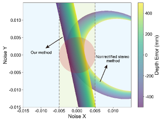
A test was performed for the nonrectified stereo method from ORB-SLAM3[22] and the proposed pseudo intersection method, as shown in Fig. 4. The test was set on a known ideal intersection at (-3000, 2000, 5000) with rays originating from (-75, 0, 0) and (75, 0, 0). The x and y values represent the noise added to the normalized direction vector of the right camera ray to simulate the mismatch and other errors. The z value represents the resulting error in depth computation in mm. The error out of [-500, 500] was filtered out for the depth output ().
In scenarios involving minimally mismatched pairs and predominant vertical error, the proposed method delivers heightened precision through effective error compensation. On the other hand, when confronted with severely mismatched pairs, the method’s commendable monotonicity ensures that high-error results are systematically excluded, aligning with the intended filtering criteria. In contrast, the unrectified stereo method diminishes the available visual information by prematurely filtering out inputs within the vertical mismatch tolerance zone. Furthermore, its nonuniform error distribution complicates the filtering process, as it encroaches upon the unreliable domain of severe mismatches, thereby extending into regions deemed unsuitable for accurate analysis.
III Experiments of the reconfigurable vision
III-A Hardware of the Reconfigurable Vision
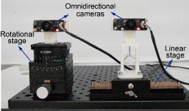
The testing platform of the reconfigurable vision consists of a dovetail groove gear rack and pinion translation stage (HLWX60-L250 by HENG YANG GUANG XUE) to provide the relative translation and a three-dimensional gear gimbal to provide the relative rotation of the two omnidirectional cameras (Fig. 5). The cameras’ lenses, SR1096A by SIR TEC, offer a wide image angle with horizontal (H: 195.95°±4°), vertical (V: 159.8°±3°), and diagonal (D: 199.2°±4°) FOV. The optical sensor of the camera is the CV4002 CMOS Image Sensor by CVSENS. To fully utilize the large horizontal FOV of our reconfigurable vision system, the cameras were aligned horizontally during the tests.
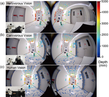
The system could be deployed in any relative pose as long as there is a common vision. For biomimetic purposes, three modes of the visual system and their specialties are demonstrated with our robotic vision test platform:
1) Herbivorous Vision: This mode features an exceptionally large FOV (316°) achieved by combining the view ranges of two omnidirectional cameras. It includes a relatively small angle of stereo vision for minimal 3D sensing (76°).
2) Carnivorous Vision: This mode offers wide-range stereo vision (136°) with a highly overlapped view, enhancing depth perception and precision. The total FOV of this mode is 256°.
3) Human Vision: This mode includes comprehensive depth vision characterized by a broad depth of field, with all its 196° vision field binocular.
These modes illustrate the adaptability and specialized functionalities of robotic vision systems inspired by biological features. To deploy the reconfigurable vision system, both omnidirectional cameras were calibrated for intrinsic parameters first. Then, the system underwent the working process, which included stereo extrinsic calibration, homologous points matching, and final depth computation. The results demonstrated consistency with our designed purpose and biomimetic avatars (Fig. 6(a-c)).
III-B Characterization of FOV
For the constant hardware, the reconfigurability of the system is demonstrated by changing the relative spatial position of the two omnidirectional cameras. With the ultra-wide FOV of these cameras, translating them primarily adjusts the baseline length of the stereo system, thereby affecting the accuracy of homologous point matching and depth computation. In contrast, rotating the cameras plays a more significant role in determining the characteristics of different vision modes, which is achieved by balancing the size of the stereo measurement zone with the extent of the blind zone, allowing for optimal performance across various biomimetic vision applications.
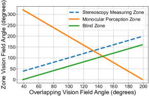
Moreover, to optimize depth measurement, the entire space is divided into three zones based on the relative poses of the two omnidirectional cameras:
1) Stereoscopy Measuring Zone: The region within the overlapped FOV used for accurate depth measurement.
2) Monocular Perception Zone: Areas where only one camera has visibility.
3) Blind Zone: Areas outside the FOV of both cameras, where no visual information is available.
This spatial division is crucial for effectively utilizing the stereo vision system and is determined by the system configurations. Based on the cameras’ FOV, the relative relation of the visual fields for the proposed three zones can be determined accordingly (Fig. 7). As the stereo measurement zone (S) increases, the monocular perception zone (M) decreases at twice the rate; the blind zone (B) increases proportionally with the stereo measurement zone (S), with an offset of 32°.
| (3) |
where S, M, and B represent the field angle of 3 zones, respectively, H represents the FOV of the omnidirectional camera used, and O represents the overlapped field angle of the binocular system.
IV Demonstration of the reconfigurable vision
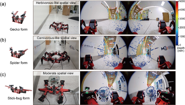
To further demonstrate the potential application of our reconfigurable vision system, we deployed it on a metamorphic quadruped robot, Origaker, which is a reconfigurable robot capable of altering its shape and mobility features by shifting its closed eight-bar linkage trunk[24]. Two omnidirectional cameras are installed on the robot’s trunk linkage. Consequently, the relative position of the two omnidirectional cameras changes as the robot’s form transforms, acquiring different vision features. The three configurations (gecko, spider, and stick-bug), of Origaker that can carry the camera system are shown in Fig. 8 and described below.
The gecko configuration provides a herbivorous-like spatial view, with a stereoscopic FOV of 76° and a monocular FOV of 316° (the widest one). The spider configuration provides a carnivorous-like spatial view, with a stereoscopic FOV of 136° and a monocular FOV of 256°. The stick-bug configuration provides a moderate spatial view, with a stereoscopic FOV of 150° (the widest one) and a monocular FOV of 242°. By adapting to these different configurations, the vision system on Origaker can exhibit varying perceptual characteristics, showcasing its versatility and robustness in different operational scenarios.
Here, to exhibit the adaptability of the reconfigurable vision, the Origaker was placed in a complex scenario for approaching a specific object in a narrow corridor and inspecting it in detail. The robot started in the gecko configuration, utilizing its wide FOV for extensive sensing and searching (Fig. 8(a)). With a relatively limited blind zone, the robot can obscurely avoid obstacles in almost all directions. The narrow field angle sensing in the center allows for minimal stereoscopic environment sensing to assist in-depth perception. After detecting the target object, the Origaker switched to the spider configuration to gain peripheral depth sensing (Fig. 8(b)). The blind zone is still less than 180°, ensuring a broad range of sensing capabilities. This configuration helps the robot accurately measure distances to the corridor walls and avoid collisions. Upon approaching the target object, the Origaker switched to the stick-bug configuration for detailed close-range observation (Fig. 8(c)). This mode offers improved camera alignment, allowing for the matching of homologous points in the immediate vicinity, which is difficult for other configurations to achieve. However, the matching process is more challenging due to the high view angle difference, and there is a higher likelihood of distant objects being blocked by closer ones. The stick-bug configuration enables precise depth measurement of nearby objects, providing a detailed view for accurate shape detection.
V Conclusions and future work
This research introduces a bio-inspired reconfigurable stereo vision system for robotics, using omnidirectional cameras to achieve adaptable visual features. Emulating animal visual adaptability, it overcomes the limitations of traditional fixed alignment of cameras and narrow FOV. Key innovations include a reconfigurable stereo vision strategy, a robust depth measurement system using a modified nonrectified geometrical method and deep neural network, and the successful deployment of the metamorphic robot Origaker. The system offers flexibility with different vision modes, such as a wide field for target seeking and a broad binocular field for detailed inspection, highlighting the potential of bio-inspired designs to enhance robotic vision adaptability in various scenarios. Future work will focus on developing a mechanical design that closely mimics the eye alignment mechanisms to deeply replicate the various visual strategies of different species. Combining embodied intelligence with this system will further improve the adaptability of our vision system.
References
- [1] H. Alfalahi, F. Renda, and C. Stefanini, “Concentric Tube Robots for Minimally Invasive Surgery: Current Applications and Future Opportunities,” IEEE Trans. Med. Robot. Bionics, vol. 2, no. 3, pp. 410–424, Aug. 2020.
- [2] L. Van Duong and V. A. Ho, “Large-Scale Vision-Based Tactile Sensing for Robot Links: Design, Modeling, and Evaluation,” IEEE Trans. Robot., vol. 37, no. 2, pp. 390–403, Apr. 2021.
- [3] J. Yang, C. Wang, B. Jiang, H. Song, and Q. Meng, “Visual Perception Enabled Industry Intelligence: State of the Art, Challenges and Prospects,” IEEE Trans. Ind. Inf., vol. 17, no. 3, pp. 2204–2219, Mar. 2021.
- [4] M. J. Schuster, K. Schmid, C. Brand, and M. Beetz, “Distributed stereo vision-based 6D localization and mapping for multi-robot teams,” Journal of Field Robotics, vol. 36, no. 2, pp. 305–332, Mar. 2019.
- [5] M. Poggi, F. Tosi, K. Batsos, P. Mordohai, and S. Mattoccia, “On the Synergies between Machine Learning and Binocular Stereo for Depth Estimation from Images: a Survey,” IEEE Trans. Pattern Anal. Mach. Intell., pp. 1–1, 2021.
- [6] W. Flores-Fuentes, G. Trujillo-Hernández, I. Y. Alba-Corpus, J. C. Rodríguez-Quiñonez, J. E. Mirada-Vega, D. Hernández-Balbuena, F. N. Murrieta-Rico, and O. Sergiyenko, “3D spatial measurement for model reconstruction: A review,” Measurement, vol. 207, p. 112321, Feb. 2023.
- [7] H. Laga, L. V. Jospin, F. Boussaid, and M. Bennamoun, “A Survey on Deep Learning Techniques for Stereo-Based Depth Estimation,” IEEE Trans. Pattern Anal. Mach. Intell., vol. 44, no. 4, pp. 1738–1764, Apr. 2022.
- [8] D. Papadimitriou and T. Dennis, “Epipolar line estimation and rectification for stereo image pairs,” IEEE Trans. on Image Process., vol. 5, no. 4, pp. 672–676, Apr. 1996.
- [9] L. Keselman, J. I. Woodfill, A. Grunnet-Jepsen, and A. Bhowmik, “Intel(R) RealSense(TM) Stereoscopic Depth Cameras,” in 2017 IEEE Conference on Computer Vision and Pattern Recognition Workshops (CVPRW). Honolulu, HI, USA: IEEE, Jul. 2017, pp. 1267–1276.
- [10] Jungong Han, Ling Shao, Dong Xu, and J. Shotton, “Enhanced Computer Vision With Microsoft Kinect Sensor: A Review,” IEEE Trans. Cybern., vol. 43, no. 5, pp. 1318–1334, Oct. 2013.
- [11] J. A. Placed, J. Strader, H. Carrillo, N. Atanasov, V. Indelman, L. Carlone, and J. A. Castellanos, “A Survey on Active Simultaneous Localization and Mapping: State of the Art and New Frontiers,” IEEE Trans. Robot., vol. 39, no. 3, pp. 1686–1705, Jun. 2023.
- [12] Y. Cong, R. Chen, B. Ma, H. Liu, D. Hou, and C. Yang, “A Comprehensive Study of 3-D Vision-Based Robot Manipulation,” IEEE Trans. Cybern., vol. 53, no. 3, pp. 1682–1698, Mar. 2023.
- [13] L. Fu, F. Gao, J. Wu, R. Li, M. Karkee, and Q. Zhang, “Application of consumer RGB-D cameras for fruit detection and localization in field: A critical review,” Computers and Electronics in Agriculture, vol. 177, p. 105687, Oct. 2020.
- [14] C. Zhang and J. Dai, “Trot Gait with Twisting Trunk of a Metamorphic Quadruped Robot,” J Bionic Eng, vol. 15, no. 6, pp. 971–981, Nov. 2018.
- [15] D. Fan, X. Yuan, W. Wu, R. Zhu, X. Yang, Y. Liao, Y. Ma, C. Xiao, C. Chen, C. Liu, H. Wang, and P. Qin, “Self-shrinking soft demoulding for complex high-aspect-ratio microchannels,” Nat Commun, vol. 13, no. 1, p. 5083, Aug. 2022.
- [16] C. A. Aubin, R. H. Heisser, O. Peretz, J. Timko, J. Lo, E. F. Helbling, S. Sobhani, A. D. Gat, and R. F. Shepherd, “Powerful, soft combustion actuators for insect-scale robots,” Science, vol. 381, no. 6663, pp. 1212–1217, Sep. 2023.
- [17] J. Fu, J. Chen, Z. Tang, Z. Wei, and J. S. Dai, “Stability Margin Based Gait Design on Slopes for a Novel Reconfigurable Quadruped Robot with a Foldable Trunk,” in 2023 IEEE International Conference on Robotics and Biomimetics (ROBIO). Koh Samui, Thailand: IEEE, Dec. 2023, pp. 1–7.
- [18] R. Baines, S. K. Patiballa, J. Booth, L. Ramirez, T. Sipple, A. Garcia, F. Fish, and R. Kramer-Bottiglio, “Multi-environment robotic transitions through adaptive morphogenesis,” Nature, vol. 610, no. 7931, pp. 283–289, Oct. 2022.
- [19] S. Miyashita, S. Guitron, S. Li, and D. Rus, “Robotic metamorphosis by origami exoskeletons,” Sci. Robot., vol. 2, no. 10, p. eaao4369, Sep. 2017.
- [20] A. Hughes, “Topographical relationships between the anatomy and physiology of the rabbit visual system,” Doc Ophthalmol, vol. 30, no. 1, pp. 33–159, Sep. 1971.
- [21] A. Hughes, “A supplement to the cat schematic eye,” Vision Research, vol. 16, no. 2, pp. 149–IN2, Jan. 1976.
- [22] C. Campos, R. Elvira, J. J. G. Rodriguez, J. M. M. Montiel, and J. D. Tardos, “ORB-SLAM3: An Accurate Open-Source Library for Visual, Visual–Inertial, and Multimap SLAM,” IEEE Trans. Robot., vol. 37, no. 6, pp. 1874–1890, Dec. 2021.
- [23] P. Lindenberger, P.-E. Sarlin, and M. Pollefeys, “LightGlue: Local Feature Matching at Light Speed,” in 2023 IEEE/CVF International Conference on Computer Vision (ICCV). Paris, France: IEEE, Oct. 2023, pp. 17 581–17 592.
- [24] Z. Tang, K. Wang, E. Spyrakos-Papastavridis, and J. S. Dai, “Origaker: A Novel Multi-Mimicry Quadruped Robot Based on a Metamorphic Mechanism,” Journal of Mechanisms and Robotics, vol. 14, no. 6, p. 060907, Dec. 2022.
- [25] J. Kannala and S. Brandt, “A generic camera model and calibration method for conventional, wide-angle, and fish-eye lenses,” IEEE Trans. Pattern Anal. Mach. Intell., vol. 28, no. 8, pp. 1335–1340, Aug. 2006.
- [26] Z. Zhang, “A flexible new technique for camera calibration,” IEEE Trans. Pattern Anal. Machine Intell., vol. 22, no. 11, pp. 1330–1334, Nov. 2000.
- [27] K. S. Arun, T. S. Huang, and S. D. Blostein, “Least-Squares Fitting of Two 3-D Point Sets,” IEEE Trans. Pattern Anal. Mach. Intell., vol. PAMI-9, no. 5, pp. 698–700, Sep. 1987.
- [28] L. Han and J. C. Bancroft, “Nearest approaches to multiple lines in n-dimensional space,” Crewes Res. Rep, vol. 22, pp. 1–17, 2010.