Nonreciprocal reflection of mid-infrared light
by highly doped InAs at low magnetic fields
Abstract
We report an experimental observation of room-temperature nonreciprocal reflection of mid-infrared light from planar highly doped InAs surfaces at low magnetic fields ranging from 0.07 T to 0.16 T. Using ellipsometry, we demonstrate that the amplitude ratio and phase shift of reflected light are nonreciprocal in the Voigt configuration. We also demonstrate using Fourier-transform infrared spectroscopy that the nonreciprocal reflectance contrast (the difference in reflectance in opposite directions) increases with the magnitude of the magnetic field for p-polarized light. Our work is a step toward the practical implementation of nonreciprocal thermal emitters and absorbers and applications such as remote magnetic field sensing.
I Introduction
Lorentz reciprocity states that a source and a detector of light can be freely interchanged without changing the outcome of the measurement by the detector [1, 2, 3]. Reciprocity is useful for applications such as telecommunication, where it implies that an antenna that is a good receiver is a good transmitter as well. However, reciprocity assumes that light propagates through media whose optical properties (i.e., permittivity, permeability, and conductivity) are (1) linear, (2) time-invariant, and (3) described by symmetric tensors. In principle, breaking one or more of these assumptions would break Lorentz reciprocity, and the medium could support “nonreciprocal” electromagnetic modes, via the electromagnetic wave equation.
In recent years, the prospect of electromagnetic nonreciprocity has become particularly exciting because it implies that Kirchhoff’s law of thermal radiation—the equality of spectral directional emissivity and absorptivity [4, 5]—can be violated [6, 7, 8, 9]. In particular, it can be shown that when nonreciprocity is present, emissivity , absorptivity , and reflectance are related by the generalized Kirchhoff’s law of thermal radiation:
| (1) |
where is the angular frequency, is the polar angle of incidence, and is the polarization of light. Eq. (1) assumes specular reflection [6, 8]; otherwise, Eq. (1) can be written in terms of the bidirectional reflectance distribution function, or BRDF [7, 9]. If the left-hand side of Eq. (1) is nonzero, it implies that Kirchhoff’s law of thermal radiation has been violated, and the difference , or nonreciprocal reflectance contrast, is a metric of the inequality of spectral directional emissivity and absorptivity.
Nonreciprocity and the violation of Kirchhoff’s law of thermal radiation have implications for the energy efficiency of devices that emit and absorb thermal radiation such as solar thermal collectors and thermophotovoltaics since they no longer have to emit as much as they absorb through any given spectral directional channel [10, 11]. In addition, nonreciprocity allows for unprecedented control of thermal radiation, such as directionally asymmetric emission and absorption. Technologies including thermal imaging, tailored thermal signatures, and radiative cooling can benefit from this level of control. For most of these applications, the emitter or absorber is at room temperature, so as a result of Wien’s law [12, 5], candidate materials should support nonreciprocal electromagnetic modes in the mid-infrared (mid-IR).
There are a number of different physical mechanisms that can enable nonreciprocity. Nonlinear media can work, but the intensity of emitted or absorbed light needs to be high (which is not the case for room-temperature thermal radiation) or some other high power input is needed to drive nonlinear effects [13, 14, 15, 16]. Space and/or time modulation can work as well and have been experimentally demonstrated at lower frequencies than the mid-IR [17, 18, 19, 20, 21]. Time modulation has been theoretically predicted to have fundamentally interesting and potentially useful consequences for thermal radiation, such as coherence and optical refrigeration [22, 23]. In particular, spatiotemporally modulated metasurfaces are tailorable and have been shown to have the potential to become platforms for mid-IR nonreciprocity [24, 25], but the required frequency modulation ( GHz) is difficult to achieve in practice. A direct current (DC) magnetic field, which breaks assumption (3) of Lorentz reciprocity by inducing antisymmetric components of the dielectric tensor, may be the most well-known approach to mid-IR nonreciprocity.
Within the scope of nonreciprocity enabled by magnetic fields, in the literature, there has been an emphasis on two classes of materials: highly doped semiconductors such as InSb and InAs, which support free-carrier magneto-optic effects [26, 27], and magnetic Weyl semimetals such as [28] and [29] (although only the former has a Curie temperature above room temperature). Theoretical research on these candidate materials shows a great deal of promise: in combination with design strategies from the field of nanophotonics, such as multilayer structures [30, 31, 32, 33], gratings [8, 34, 35, 36], metamaterials [37], and prisms [38], InAs-based absorbers have been theoretically predicted to be able to “totally” violate Kirchhoff’s law, i.e., nearly 100 emissivity and 0 absorptivity at a given frequency and angle of incidence [8, 34, 32]. However, the magnetic fields required can be large, up to T, comparable to that generated by a magnetic resonance imaging (MRI) scanner. On the other hand, magnetic Weyl semimetals are theoretically predicted to support stronger nonreciprocity than InAs without the need for applied magnetic fields. This is because in the electronic band structure of these materials, the Berry curvature flux between Weyl nodes of opposite chirality behaves like a pseudo-magnetic field in momentum space [39], giving rise to the anomalous Hall effect and large off-diagonal components of the dielectric tensor compared to the diagonal components [40, 41, 9, 42].
Despite the vast body of work on theoretically predicting and optimizing nonreciprocal emission and absorption in the mid-IR, experiments are scarce [43]. Although magneto-optic effects such as the Faraday effect have been explored in the context of magnetic Weyl semimetals [44], to date, there have been no direct observations of mid-IR nonreciprocity, e.g., measurements of directionally asymmetric (“nonreciprocal”) reflectance , where is the angular frequency and is the polar angle of incidence. Historically, InAs and InSb have been the platforms of choice for experimental demonstrations of magnetic-field-enabled mid-IR nonreciprocity. Although some experiments have succeeded in directly observing nonreciprocity in lightly doped InAs and InSb [6, 45, 46], these results have limited applications to thermal radiation because of cryogenic temperatures and/or low frequencies (on the order of THz instead of THz). More recent experiments that used lightly doped InSb in combination with metasurfaces have similar limitations [47, 48, 49], although the Verdet constant (which is related to the off-diagonal components of the dielectric tensor) of highly doped InSb has been measured in the mid-IR [50]. In the past few years, highly doped InAs has been used to experimentally demonstrate nonreciprocal absorption in the mid-IR via guided-mode resonances [51] and epsilon-near-zero (ENZ) modes [52]. In fact, the violation of Kirchhoff’s law was directly observed in these systems, i.e., experimental values of spectral directional emissivity and absorptivity were not equal [53, 54]. However, similar to many theoretical predictions, these experiments required large magnetic fields ranging from 0.5 T to 1.5 T, which may not be practical or integrable. Strong nonreciprocity is theoretically possible for these materials at magnetic fields as low as 0.3 T (to be discussed, see also [34], for example), but experiments in this regime are lacking. Given this limitation and the small number of experiments that have been conducted on highly doped semiconductors in the context of mid-IR nonreciprocity, more work is needed to fully understand their capabilities, especially at low magnetic fields.
To help fill these gaps, we investigated the mid-IR nonreciprocal optical response of planar highly doped InAs surfaces at magnetic fields ranging from 0.07 T to 0.16 T, which were generated using off-the-shelf neodymium magnets. Using ellipsometry, we experimentally observed that the amplitude ratio and phase difference between s- and p-polarized light, and , are nonreciprocal in the Voigt configuration (magnetic field pointing normal to the plane of incidence). In addition, we showed that it is possible to fit the dielectric tensor of highly doped InAs to measured and spectra, without the need for time-consuming Mueller matrix measurements. Then, using Fourier-transform infrared spectroscopy (FTIR), we experimentally observed that the reflectance of p-polarized light is nonreciprocal and that the nonreciprocal reflectance contrast, defined as the difference in reflectance in opposite directions and , increases with increasing magnetic field. Our work demonstrates that measurable nonreciprocal reflectance contrasts can be achieved at low magnetic fields, at thermally relevant wavelengths in the mid-IR. This is an important step toward making nonreciprocal thermal emitters and absorbers practical, which has the potential to improve technologies such as solar energy harvesting, thermal imaging, thermal management, and radiative cooling.
In what follows, we will review the theory of nonreciprocal reflection due to free-carrier magneto-optic effects in highly doped semiconductors. Then, we will describe our experimental setups for ellipsometry and FTIR and the magnetization schemes we designed and implemented. Finally, we will discuss the results of our experiments and share our outlook on the field of nonreciprocal thermal radiation, with an emphasis on the potential of highly doped III-V semiconductors in the same family as InAs.
II Theory
II.1 Material model and reflection coefficients
Generally speaking, free-carrier magneto-optic effects can be modeled using the gyrotropic Drude-Lorentz model [55]. In this extension of the Drude model, the Lorentz force is included, which gives rise to off-diagonal components of the dielectric tensor. If the magnetic field points in the -direction, i.e., , the dielectric tensor can be written in the form
| (2) |
where and are the transverse and longitudinal components of and is the gyration vector. These depend on and as follows:
| (3) | ||||
| (4) | ||||
| (5) |
In Eqs. (3)–(5), is the high-frequency dielectric constant, is the plasma frequency, is the cyclotron frequency, and is the damping constant. Furthermore, is the carrier concentration, is the electronic effective mass, and and are the elementary charge and permittivity of free space, respectively. Equations (2)–(5) are applicable to magnetoplasmas and materials that support free-carrier magneto-optic effects, such as highly doped InAs, InSb, and other -type semiconductors.
Now consider the interface between air (having dielectric constant 1) and a magneto-optic material having a dielectric tensor of the form of Eq. (2). It is known from symmetry arguments [6, 56, 57] that nonreciprocal reflectance is maximized in the Voigt configuration, where B is perpendicular to the plane of incidence or wavevector of light. The other limiting case is the Faraday configuration, where B is parallel to the plane of incidence and reflection is reciprocal. In Eq. (2), B points in the -direction, so light propagates in the -plane, as illustrated in Fig. 1(a). In the Voigt configuration, the electromagnetic modes supported by the magneto-optic material are p- and s-polarized, which greatly simplifies the analysis since there is no rotation of the plane of polarization upon reflection. It can be shown that the p- and s-polarized reflection coefficients are
| (6) | |||||
| (7) |
where the superscripts , , and indicate incident, reflected and transmitted light, respectively [6, 58, 42]. In Eqs. (6) and (7), , where is the speed of light in free space, is the -component of the wavevector, and is the -component of the wavevector in air. In the magneto-optic material, the -component of the wavevector is polarization-dependent (i.e., it is birefringent):
| (8) | ||||
| (9) |
Equations (6)–(9) assume that the relative permeabilities of both materials is 1, which is a reasonable assumption at optical frequencies [2, 59]. Note that only p-polarized light is nonreciprocal since has terms that are linear in , such that . The linear coefficient in this case is , which is nothing more than the -dependent off-diagonal component of the antisymmetric dielectric tensor . If , these terms vanish, the dielectric tensor becomes symmetric, and becomes reciprocal. On the other hand, s-polarized light is always reciprocal because its dispersion relation (Eq. (9)) does not depend on ; it behaves like light in an isotropic material having dielectric constant .
II.2 Nonreciprocal measureables
Nonreciprocity can manifest itself in a number of different measureables that are related to the reflection coefficients. In FTIR, the reflectance () is measured. If the sample is sufficiently optically thick such that there is no transmission, then the absorptivity can be calculated as . Information about thermal emission properties of the material can be inferred from the Onsager-Casimir reciprocal relations [60] (or adjoint Kirchhoff’s law [61]):
| (10) | ||||
| (11) |
where is the emissivity. In addition, Eqs. (10) and (11) imply that flipping the sign of is equivalent to flipping the sign of , i.e., . This is extremely useful in experiments since it is usually easier to reverse the direction of B (i.e., from to ) than it is to send light backwards from the detector to the source.
In ellipsometry, the ratio of to —a complex number—is measured in terms of its amplitude and phase. More specifically, if
| (12) |
the ellipsometer measures and , the amplitude ratio and phase difference between p- and s-polarized light, respectively [62]. Since ellipsometry essentially measures a ratio, it can be highly sensitive and less susceptible to perturbations such as scattering and low intensity since they affect both the numerator and denominator, thus “canceling out.” For this reason, ellipsometry could be a more unambiguous way to experimentally probe nonreciprocity than FTIR.
III Experiments
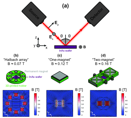
Having reviewed the theory of nonreciprocal reflection, we now proceed to describing our experimental results. Figure 1(a) illustrates the experimental setup in both ellipsometry and FTIR (treating the source and detector of each one as black boxes, although they are different). Polarized light ( or in Fig. 1(a)) is sent from the source toward a magnetized InAs wafer at polar angle of incidence . The magnetic field B points in the -direction, which means that the entire system is in the Voigt configuration. The incident light is specularly reflected at the interface between air and the InAs wafer and collected by the detector. The ellipsometer we used was a J. A. Woollam Co. IR-VASE® Mark II, which allowed us to automatically control through the included software (WVASE®). The FTIR we used was a Thermo Scientific™ Nicolet™ iS50 FTIR Spectrometer. In this case, a PIKE Technologies VeeMAX III was used to manually control , in conjunction with a ZnSe polarizer inserted into the accessory to manually control polarization.
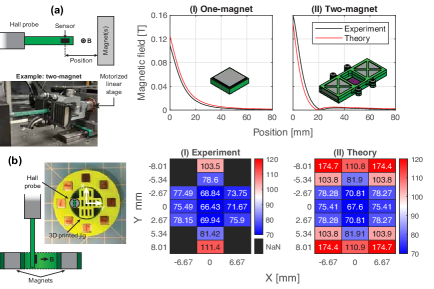
To control , we designed three magnetization schemes using off-the-shelf neodymium magnets (K&J Magnetics, Inc.), which are illustrated in Figs. 1(b)–(d). Each magnetization scheme consists of an array of neodymium magnets held in place using a 3D printed holder and was designed to produce a magnetic field that is uniform in magnitude and direction across the InAs wafer. This can be seen in the magnetic field distribution plotted below each magnetization scheme in Figs. 1(b)–(d). These were calculated using COMSOL Multiphysics®. The “Halbach array” magnetization scheme produces a magnetic field of T, as shown in Fig. 1(b). “One-magnet” produces T (Fig. 1(c)), and “two-magnet” produces T (Fig. 1(d)). The calculated values of were experimentally validated by measuring the magnetic field as a function of position using a handheld teslameter. Details of the experimental validation can be found in Fig. S1 in the Supplementary Material. Including T, this gave us the ability to measure four different levels of .
Finally, we measured two InAs wafers, both of which were purchased from MSE Supplies LLC. Each sample was a square of side length 15 mm and 0.5 mm thick. We found that the doping levels of the samples were slightly different, which led to different strengths of nonreciprocity, to be discussed in the following sections.
IV Results and discussion
IV.1 Ellipsometry
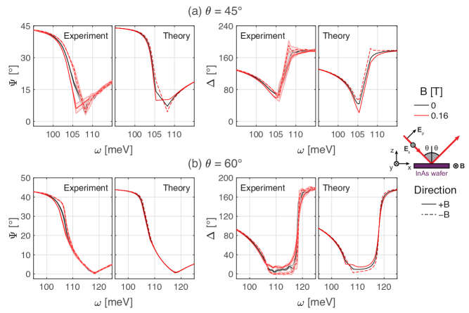
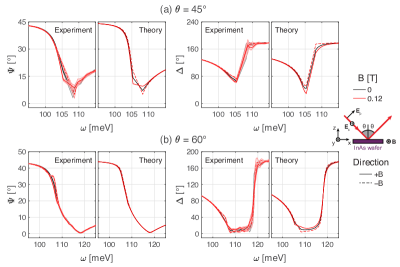
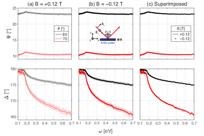
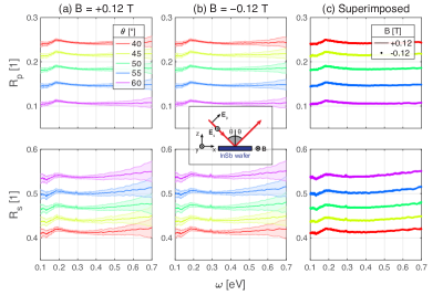
Figure 2 shows the results we obtained using ellipsometry. We measured and at two -values: 45°and 60°, shown in Figs. 2(a) and (b), respectively. In each panel, two values of are shown: 0 T and 0.16 T (two-magnet), corresponding to black and red lines. Data for T can be found in Fig. S2 in the Supplementary Material. Solid and dotted lines represent pointing in the - and -directions, respectively, which is equivalent to flipping the sign of via Eqs. (10)–(11). Experimental and theoretical and spectra experimental are shown. In the experimental values, the shaded areas represent the standard deviation of scans.
Since and can be written as closed-form expressions using Eqs. (6)–(9), the data can be fitted to the gyrotropic Drude-Lorentz model, the fit parameters being , , , and . Typically, to fit the dielectric tensor of an anisotropic material, and measurements are not sufficient. Instead, the Mueller matrix is measured, which, although a standard procedure the vast majority of ellipsometers are capable of, can be extremely time-consuming—on the order of several hours per spectrum, and more than one spectrum, i.e., as a function of , is usually needed for a good fit. By taking advantage of the symmetries of the Voigt configuration and the resulting simplicity of the equations for and , we circumvented the need for Mueller matrix measurements and fitted the dielectric tensor of the sample using and as if it were isotropic. The results of the fit were , , , and meV. Hall effect measurements showed good agreement with the fitted value of ( error). These values are comparable to those reported in the literature for similar experiments on mid-IR nonreciprocity [51, 53, 52, 54].
Generally speaking, there is good agreement between experimental and theoretical values of and . There are two signatures of nonreciprocal reflection in the results: (1) and likewise for , and (2) the contrast between measurements at and increases with the magnitude of , in an approximately monotonic way. These signatures are clearer for (Fig. 2(b)), especially when looking at in the band 105–115 meV. The reason is that (Eq. (3)) is near zero in this band [52]. In Eq. (6), the terms are always reciprocal because they do not linearly depend on , whereas the terms are always nonreciprocal as long as . In the limit as , it can be shown that the reciprocal terms vanish and , which only depends on and the frequency and direction of the incident light.
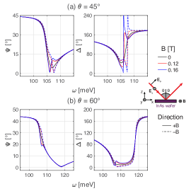
If and are calculated using a finer spectral resolution, there are a number of sharp features present in the theoretical values of and that are not apparent in the experimental values. This is shown in Fig. S3 in the Supplementary Material. However, this could be because of the spectral resolution of the ellipsometer, which was 8 ( meV). A finer spectral resolution may have been able to resolve the sharp features, but this would have made the measurements much more time-consuming. On the other hand, it is worth noting that the sharp features could be used as spectral signatures for remote magnetic field sensing because (1) they are only present when , (2) their bandwidth depends on the magnitude of , and (3) their frequency (red- or blueshifted) depends on the direction of . These trends can be seen in Fig. 2(a) but not in Fig. 2(b), which means that the sharp features are sensitive to as well. Since their bandwidth, frequency, and very presence are sensitive to and , in principle, precise measurement of these spectral signatures could be used to remotely sense both the magnitude and the direction of a magnetic field using mid-IR light.
Ellipsometry has given us insight into how sensitive mid-IR nonreciprocity can be. Although nonreciprocity is sometimes thought of as “weak” in the sense that it is small effect that is difficult to measure and make practical use of and there are few candidate materials, our results suggest that experimental techniques such as ellipsometry can be highly sensitive to nonreciprocity, even at magnetic fields an order of magnitude lower than those generated in prior work ( T compared to T).
IV.2 FTIR
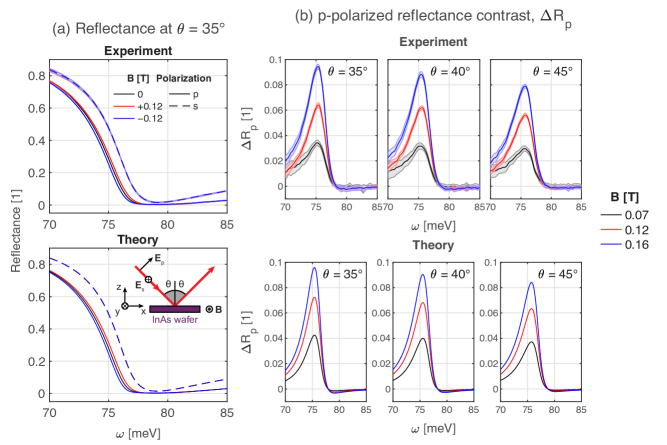
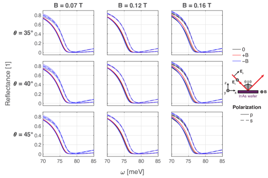
Figure 3 shows the results we obtained using FTIR. Figure 3(a) shows the experimental and theoretical and spectra, using as an example. Similar to ellipsometry, the data can be fitted to the gyrotropic Drude-Lorentz model using Eqs. (6)–(9) since they are closed-form expressions. The doping level of the sample we used in these experiments was different from the one used in the previous section. We found that , , , and meV. In Fig. 3(a), there is good agreement between theory and experiments. As expected, is reciprocal (dashed lines) and is nonreciprocal (solid lines). In Fig. 3(a), the shaded areas represent the standard deviation of scans. In the case of , there does not appear to be any statistically significant differences between the reflectance spectra as a function of , whereas in the case of , the reflectance spectra are well-separated with little to no overlap in the error bars.
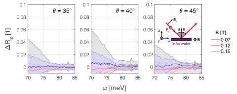
To comprehensively understand the nonreciprocity of , we define the nonreciprocal reflectance contrast:
| (13) |
Using Eq. (7), it can be shown that , regardless of the values of , , and . We experimentally confirmed this and plot the experimental values of with error bars in Fig. S5 in the Supplementary Material. Figure 3(b) shows (i) experimental and (ii) theoretical values of . Again, there is good agreement between theory and experiments; even small features such as the dip below zero after the peak in seem to appear in the experimental values (just below 80 meV). There are two notable trends in the data: (1) increases with increasing , as expected, and (2) decreases with increasing . Prior work has suggested that nonreciprocity should be stronger at grazing angles of incidence, e.g., due to coupling to nonreciprocal surface plasmon polaritons [41, 9]. However, our results suggest that, at least in the absence of couplers such as gratings and prisms, nonreciprocity is stronger at lower angles of incidence. This is corroborated by the results shown in Fig. 2: compared to , and change much more drastically as a function of at . However, it should be pointed out that at normal incidence (), because of symmetry, meaning that there exists a value that maximizes . For the first and second samples, we theoretically predict that these values are 20.1°and 28.7°, respectively.
Our results show that statistically significant nonreciprocity can be experimentally observed even at low magnetic fields. In this case, we measured a maximum nonreciprocal reflectance contrast as low as at T and as high as at T. As discussed in Sec. IV.1, the ability to measure changes in in response to small changes in points toward applications in remote magnetic field sensing. In fact, measuring both and can have advantages over measuring and . For example, the maximum nonreciprocal reflectance contrast does not seem to red- or blueshift as a function of , which means they can be measured at a single appropriately chosen wavelength to sense . (This may not be true at high magnetic fields since can be dependent on , which would limit the range of values that can be sensed.) In addition, since is always zero, it can be used for calibration or as a litmus test of the fidelity of the measurement.
V Conclusion
In this work, we experimentally observed nonreciprocal reflection of mid-IR light by highly doped InAs at low magnetic fields using two experimental techniques: ellipsometry and FTIR. We showed that and as well as and are nonreciprocal, i.e., they are directionally asymmetric with respect to or, equivalently, . Our experiments showed good agreement with theory, experimentally validating the gyrotropic Drude-Lorentz model and showing that it is possible to fit the dielectric tensor using and (or even and ), without the need for Mueller matrix measurements. Our experiments demonstrated that can be large enough to be measured at magnetic fields as low as 0.07 T without the need for couplers such as gratings and prisms, suggesting that nonreciprocal thermal emitters and absorbers can be simpler in design. Our results suggest that spectra measured using both ellipsometry and FTIR can be sensitive to the magnitude and direction of the external magnetic field, pointing toward the possibility of remote magnetic field sensing using mid-IR light.
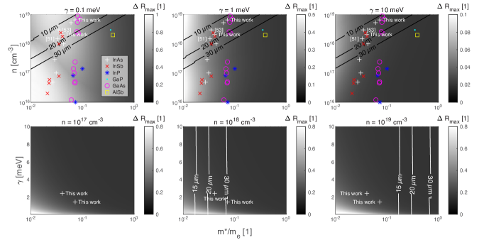
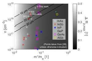
Although InAs has been the most popular platform for mid-IR nonreciprocity, there are other highly doped semiconductors that are known to host magnetoplasmons and are underexplored [26, 27]. To illustrate this parameter space, we plot as a function of and , assuming , meV, and T. This is shown in Fig. 4. The different colored points in Fig. 4 are taken from [26] (unless otherwise indicated) and represent different III-V semiconductors in the same family as InAs. As can be seen, and span a wide range of values, but InAs, InSb, and GaAs seem the most promising since their maximum values of are relatively high and lie in the mid-IR, indicated by the contour lines in black. It also appears that is the more decisive factor that determines the strength of nonreciprocity, as does not seem to change much as a function of . This makes sense, however, since the magnitude of the off-diagonal component of the dielectric tensor , which is causes nonreciprocity, depends on and (see Eq. (5)). In spite of this, the importance of cannot be understated because it sets the ENZ frequencies. In Fig. 4, can take a much wider range of values than , but only some values are predicted to support mid-IR nonreciprocity (, where is the wavelength). This is highlighted by the contour lines. For example, measurements of , , , and for a sample of InSb (MSE Supplies LLC) that does not have a high enough can be found in Figs. S6 and S7 in the Supplementary Material. Despite being magnetized by a 0.12 T magnetic field, the optical response in the mid-IR is effectively reciprocal because ENZ frequencies are far away. With this in mind, the main conclusions of Fig. 4 are that should be as low as possible (to maximize nonreciprocity) and should be as high as possible (to set the ENZ frequencies in the mid-IR).
Further analysis in which is fixed and is variable is shown in Fig. S8 in the Supplementary Material and generally indicates that some loss can increase up to a point and that too little loss can decrease . In fact, it can be proven that in the limit as , , which implies that nonreciprocal reflection is consequence of nonreciprocal absorption, which is the fundamental physical process at work.
It is worth noting that in Fig. 4 and throughout this work, we assumed that is independent of , , and when in reality, this may not be the case [26, 63]. The points in Fig. 4 were all measured at different values of and (although they were measured at room temperature). Assuming is constant seems to be a reasonable assumption given the good agreement between theory and experiments in this work and prior work. In the future, a better understanding of the relationships between the gyrotropic Drude-Lorentz model parameters could be extremely valuable, particularly in the context of nonreciprocity.
Going forward, although magnetic Weyl semimetals seem like the ideal solution for mid-IR nonreciprocity, they can be difficult to source. Highly doped semiconductors and nanofabrication with them are mature technologies in comparison, so future work in the field of nonreciprocal thermal radiation could benefit from exploring their potential. This includes measurements of their dielectric tensors and nonreciprocal reflectance contrast as a function of magnetic field. Experimental demonstrations of nanophotonically-enhanced nonreciprocal thermal radiation (beyond what has already been achieved) would be valuable since in principle, the spectral, directional, and polarization characteristics of thermal radiation can be fully controlled using nanophotonics. For example, since s-polarized light is reciprocal, it can have a parasitic effect on nonreciprocity since on average, real-world thermal emitters equally emit both polarizations of light. Therefore, even if , if , then the polarization averaged nonreciprocal reflection contrast is only 0.5. Using, e.g., ENZ modes to suppress s-polarized emission and absorption would help alleviate this.
Funding
S. P., Y. T., and S. V. B. acknowledge support from ARO MURI (Grant No. W911NF-19-1-0279) via U. Michigan. S. P. gratefully acknowledges support from the NSF GRFP under Grant No. 2141064.
Acknowledgments
The authors thank Arun Nagpal, Qiuyuan Wang, Taqiyyah Safi, Luqiao Liu, Thanh Nguyen, Manasi Mandal, Mingda Li, Steven Kooi, and Caroline Ross for helpful discussions about magnetic materials, magneto-optic effects, and nonreciprocity over the course of this project. The authors thank Tim McClure and Charlie Settens for training and help with Fourier-transform infrared spectroscopy; Kevin Grossklaus and John McElearney for training and help with ellipsometry and Hall effect measurements; David Bono and Brian Neltner for their advice on measuring magnetic fields; Donal Jamieson and Kurt Broderick for training at MIT.nano; Shaymus Hudson for training and help with polishing; Duo Xu for help with 3D printing and measuring magnetic field; and Remi Sandell for help with design and prototyping during the early stages of this project. This work was carried out in part through the use of MIT.nano’s facilities. Ellipsometry was performed at the Tufts Epitaxial Core Facility using equipment supported by the United States Office of Naval Research (No. ONR DURIP N00014-17-1-2591). This material is based upon work sponsored (in part) by the U.S. Army DEVCOM ARL Army Research Office through the MIT Institute for Soldier Nanotechnologies under Cooperative Agreement number W911NF-23-2-0121.
Disclosures
The authors declare no conflicts of interest.
Data Availability Statement
Data underlying the results presented in this paper are not publicly available at this time but may be obtained from the authors upon reasonable request. CAD models of the magnetization schemes shown in Fig. 1 may be obtained from the authors upon request.
References
- [1] H. A. Lorentz, “The theorem of Poynting concerning the energy in the electromagnetic field and two general propositions concerning the propagation of light,” Amsterdammer Akademie der Wetenschappen, vol. 4, p. 176, 1896.
- [2] L. D. Landau, E. M. Lifshitz, and L. P. Pitaevskii, Electrodynamics of Continuous Media, vol. 8. Elmsford, NY: Pergamon Press, Ltd., 2 ed., 1984.
- [3] V. S. Asadchy, M. S. Mirmoosa, A. Díaz-Rubio, S. Fan, and S. A. Tretyakov, “Tutorial on electromagnetic nonreciprocity and its origins,” Proceedings of the IEEE, vol. 108, no. 10, pp. 1684–1727, 2020.
- [4] G. Kirchhoff, “Ueber das Verhältniss zwischen dem Emissionsvermögen und dem Absorptionsvermögen der Körper für Wärme und Licht,” Annalen der Physik, vol. 185, no. 2, pp. 275–301, 1860.
- [5] J. R. Howell, M. P. Mengüc, K. Daun, and R. Siegel, Thermal radiation heat transfer. Boca Raton, FL: CRC Press, 7 ed., 2020.
- [6] L. Remer, E. Mohler, W. Grill, and B. Lüthi, “Nonreciprocity in the optical reflection of magnetoplasmas,” Physical Review B, vol. 30, no. 6, p. 3277, 1984.
- [7] W. C. Snyder, Z. Wan, and X. Li, “Thermodynamic constraints on reflectance reciprocity and Kirchhoff’s law,” Applied Optics, vol. 37, no. 16, pp. 3464–3470, 1998.
- [8] L. Zhu and S. Fan, “Near-complete violation of detailed balance in thermal radiation,” Physical Review B, vol. 90, no. 22, p. 220301, 2014.
- [9] Y. Tsurimaki, X. Qian, S. Pajovic, F. Han, M. Li, and G. Chen, “Large nonreciprocal absorption and emission of radiation in type-I Weyl semimetals with time reversal symmetry breaking,” Physical Review B, vol. 101, no. 16, p. 165426, 2020.
- [10] M. A. Green, “Time-asymmetric photovoltaics,” Nano Letters, vol. 12, no. 11, pp. 5985–5988, 2012.
- [11] Y. Park, B. Zhao, and S. Fan, “Reaching the ultimate efficiency of solar energy harvesting with a nonreciprocal multijunction solar cell,” Nano Letters, vol. 22, no. 1, pp. 448–452, 2021.
- [12] W. Wien, “Ueber die energievertheilung im emissionsspectrum eines schwarzen körpers,” Annalen der Physik, vol. 294, no. 8, pp. 662–669, 1896.
- [13] L. Fan, J. Wang, L. T. Varghese, H. Shen, B. Niu, Y. Xuan, A. M. Weiner, and M. Qi, “An all-silicon passive optical diode,” Science, vol. 335, no. 6067, pp. 447–450, 2012.
- [14] A. M. Mahmoud, A. R. Davoyan, and N. Engheta, “All-passive nonreciprocal metastructure,” Nature Communications, vol. 6, no. 1, p. 8359, 2015.
- [15] Y. Shi, Z. Yu, and S. Fan, “Limitations of nonlinear optical isolators due to dynamic reciprocity,” Nature Photonics, vol. 9, no. 6, pp. 388–392, 2015.
- [16] M. Lawrence, D. R. Barton III, and J. A. Dionne, “Nonreciprocal flat optics with silicon metasurfaces,” Nano Letters, vol. 18, no. 2, pp. 1104–1109, 2018.
- [17] Z. Yu and S. Fan, “Complete optical isolation created by indirect interband photonic transitions,” Nature Photonics, vol. 3, no. 2, pp. 91–94, 2009.
- [18] H. Lira, Z. Yu, S. Fan, and M. Lipson, “Electrically driven nonreciprocity induced by interband photonic transition on a silicon chip,” Physical Review Letters, vol. 109, no. 3, p. 033901, 2012.
- [19] Y. Hadad, J. C. Soric, and A. Alu, “Breaking temporal symmetries for emission and absorption,” Proceedings of the National Academy of Sciences, vol. 113, no. 13, pp. 3471–3475, 2016.
- [20] S. Taravati and C. Caloz, “Mixer-duplexer-antenna leaky-wave system based on periodic space-time modulation,” IEEE Transactions on Antennas and Propagation, vol. 65, no. 2, pp. 442–452, 2016.
- [21] A. E. Cardin, S. R. Silva, S. R. Vardeny, W. J. Padilla, A. Saxena, A. J. Taylor, W. J. Kort-Kamp, H.-T. Chen, D. A. Dalvit, and A. K. Azad, “Surface-wave-assisted nonreciprocity in spatio-temporally modulated metasurfaces,” Nature Communications, vol. 11, no. 1, p. 1469, 2020.
- [22] R. Yu and S. Fan, “Manipulating coherence of near-field thermal radiation in time-modulated systems,” Physical Review Letters, vol. 130, no. 9, p. 096902, 2023.
- [23] R. Yu and S. Fan, “Time-modulated near-field radiative heat transfer,” Proceedings of the National Academy of Sciences, vol. 121, no. 17, p. e2401514121, 2024.
- [24] A. Ghanekar, J. Wang, S. Fan, and M. L. Povinelli, “Violation of Kirchhoff’s law of thermal radiation with space–time modulated grating,” ACS Photonics, vol. 9, no. 4, pp. 1157–1164, 2022.
- [25] A. Ghanekar, J. Wang, C. Guo, S. Fan, and M. L. Povinelli, “Nonreciprocal thermal emission using spatiotemporal modulation of graphene,” ACS Photonics, vol. 10, no. 1, pp. 170–178, 2022.
- [26] E. D. Palik and G. B. Wright, “Free-carrier magnetooptical effects,” in Semiconductors and Semimetals, vol. 3, pp. 421–458, Elsevier, 1967.
- [27] A. Zvezdin and V. Kotov, Modern magnetooptics and magnetooptical materials. Boca Raton, FL: CRC Press, 1 ed., 1997.
- [28] I. Belopolski, K. Manna, D. S. Sanchez, G. Chang, B. Ernst, J. Yin, S. S. Zhang, T. Cochran, N. Shumiya, H. Zheng, et al., “Discovery of topological Weyl fermion lines and drumhead surface states in a room temperature magnet,” Science, vol. 365, no. 6459, pp. 1278–1281, 2019.
- [29] N. Morali, R. Batabyal, P. K. Nag, E. Liu, Q. Xu, Y. Sun, B. Yan, C. Felser, N. Avraham, and H. Beidenkopf, “Fermi-arc diversity on surface terminations of the magnetic Weyl semimetal Co3Sn2S2,” Science, vol. 365, no. 6459, pp. 1286–1291, 2019.
- [30] J. Wu, F. Wu, T. Zhao, M. Antezza, and X. Wu, “Dual-band nonreciprocal thermal radiation by coupling optical Tamm states in magnetophotonic multilayers,” International Journal of Thermal Sciences, vol. 175, p. 107457, 2022.
- [31] J. Wu, Z. Wang, B. Wu, Z. Shi, and X. Wu, “The giant enhancement of nonreciprocal radiation in Thue-morse aperiodic structures,” Optics & Laser Technology, vol. 152, p. 108138, 2022.
- [32] L. Wang, F. J. García de Abajo, and G. T. Papadakis, “Maximal violation of Kirchhoff’s law in planar heterostructures,” Physical Review Research, vol. 5, no. 2, p. L022051, 2023.
- [33] H. Gold, S. Pajovic, A. Mukherjee, and S. V. Boriskina, “Gaga for nonreciprocal emitters: genetic algorithm gradient ascent optimization of compact magnetophotonic crystals,” Nanophotonics, vol. 13, no. 5, pp. 773–792, 2024.
- [34] B. Zhao, Y. Shi, J. Wang, Z. Zhao, N. Zhao, and S. Fan, “Near-complete violation of Kirchhoff’s law of thermal radiation with a 0.3 T magnetic field,” Optics Letters, vol. 44, no. 17, pp. 4203–4206, 2019.
- [35] J. Wu, F. Wu, T. Zhao, and X. Wu, “Tunable nonreciprocal thermal emitter based on metal grating and graphene,” International Journal of Thermal Sciences, vol. 172, p. 107316, 2022.
- [36] J. Wu and Y. M. Qing, “The enhancement of nonreciprocal radiation for light near to normal incidence with double-layer grating,” Advanced Composites and Hybrid Materials, vol. 6, no. 3, p. 87, 2023.
- [37] J. Li, B. Wang, and J. Wu, “Si/InAs/Ag metamaterial for strong nonreciprocal thermal emitter with dual polarization under a 0.9 T magnetic field,” Applied Materials Today, vol. 39, p. 102345, 2024.
- [38] X. Wu, “The promising structure to verify the Kirchhoff’s law for nonreciprocal materials,” ES Energy & Environment, vol. 12, no. 3, pp. 46–51, 2021.
- [39] B. Yan and C. Felser, “Topological materials: Weyl semimetals,” Annual Review of Condensed Matter Physics, vol. 8, no. 1, pp. 337–354, 2017.
- [40] J. Hofmann and S. Das Sarma, “Surface plasmon polaritons in topological Weyl semimetals,” Physical Review B, vol. 93, no. 24, p. 241402, 2016.
- [41] B. Zhao, C. Guo, C. A. Garcia, P. Narang, and S. Fan, “Axion-field-enabled nonreciprocal thermal radiation in Weyl semimetals,” Nano Letters, vol. 20, no. 3, pp. 1923–1927, 2020.
- [42] S. Pajovic, Y. Tsurimaki, X. Qian, and G. Chen, “Intrinsic nonreciprocal reflection and violation of Kirchhoff’s law of radiation in planar type-I magnetic Weyl semimetal surfaces,” Physical Review B, vol. 102, no. 16, p. 165417, 2020.
- [43] S. Yang, M. Liu, C. Zhao, S. Fan, and C.-W. Qiu, “Nonreciprocal thermal photonics,” Nature Photonics, pp. 1–13, 2024.
- [44] X. Han, A. Markou, J. Stensberg, Y. Sun, C. Felser, and L. Wu, “Giant intrinsic anomalous terahertz Faraday rotation in the magnetic Weyl semimetal Co 2 MnGa at room temperature,” Physical Review B, vol. 105, no. 17, p. 174406, 2022.
- [45] J. Heyman, P. Neocleous, D. Hebert, P. Crowell, T. Müller, and K. Unterrainer, “Terahertz emission from GaAs and InAs in a magnetic field,” Physical Review B, vol. 64, no. 8, p. 085202, 2001.
- [46] J. Chochol, K. Postava, M. Čada, and J. Pištora, “Experimental demonstration of magnetoplasmon polariton at InSb (InAs)/dielectric interface for terahertz sensor application,” Scientific Reports, vol. 7, no. 1, p. 13117, 2017.
- [47] E. Keshock, P. Peng, J. Zhou, and D. Talbayev, “Nonreciprocal Fabry-Perot effect and performance enhancement in a magneto-optical InSb-based Faraday terahertz isolator,” Optics Express, vol. 28, no. 25, pp. 38280–38292, 2020.
- [48] P. Peng, G. Thapa, J. Zhou, and D. Talbayev, “Magneto-optical nonreciprocity without chirality: Archimedean spirals on InSb,” Optics Express, vol. 30, no. 10, pp. 17193–17203, 2022.
- [49] P. Peng, G. Thapa, J. Zhou, and D. Talbayev, “Emergent optical nonreciprocity and chirality-controlled magneto-optical resonance in a hybrid magneto–chiral metamaterial,” Optica, vol. 10, no. 2, pp. 155–161, 2023.
- [50] N. Peard, D. Callahan, J. C. Perkinson, Q. Du, N. S. Patel, T. Fakhrul, J. LeBlanc, C. A. Ross, J. Hu, and C. Y. Wang, “Magneto-optical properties of InSb for infrared spectral filtering,” Journal of Applied Physics, vol. 129, no. 20, 2021.
- [51] K. J. Shayegan, B. Zhao, Y. Kim, S. Fan, and H. A. Atwater, “Nonreciprocal infrared absorption via resonant magneto-optical coupling to InAs,” Science Advances, vol. 8, no. 18, p. eabm4308, 2022.
- [52] M. Liu, S. Xia, W. Wan, J. Qin, H. Li, C. Zhao, L. Bi, and C.-W. Qiu, “Broadband mid-infrared non-reciprocal absorption using magnetized gradient epsilon-near-zero thin films,” Nature Materials, vol. 22, no. 10, pp. 1196–1202, 2023.
- [53] K. J. Shayegan, S. Biswas, B. Zhao, S. Fan, and H. A. Atwater, “Direct observation of the violation of Kirchhoff’s law of thermal radiation,” Nature Photonics, vol. 17, no. 10, pp. 891–896, 2023.
- [54] K. J. Shayegan, J. S. Hwang, B. Zhao, A. P. Raman, and H. A. Atwater, “Broadband nonreciprocal thermal emissivity and absorptivity,” Light: Science & Applications, vol. 13, no. 1, p. 176, 2024.
- [55] K. Seeger, Semiconductor Physics: An Introduction. New York, NY: Springer-Verlag Berlin Heidelberg, 9 ed., 2004.
- [56] R. E. Camley, “Nonreciprocal surface waves,” Surface Science Reports, vol. 7, no. 3-4, pp. 103–187, 1987.
- [57] A. Figotin and I. Vitebsky, “Nonreciprocal magnetic photonic crystals,” Physical Review E, vol. 63, no. 6, p. 066609, 2001.
- [58] A. B. Khanikaev and M. Steel, “Low-symmetry magnetic photonic crystals for nonreciprocal and unidirectional devices,” Optics Express, vol. 17, no. 7, pp. 5265–5272, 2009.
- [59] P. Pershan, “Magneto-optical effects,” Journal of Applied Physics, vol. 38, no. 3, pp. 1482–1490, 1967.
- [60] H. B. G. Casimir, “On Onsager’s principle of microscopic reversibility,” Reviews of Modern Physics, vol. 17, no. 2–3, p. 343, 1945.
- [61] C. Guo, B. Zhao, and S. Fan, “Adjoint Kirchhoff’s law and general symmetry implications for all thermal emitters,” Physical Review X, vol. 12, no. 2, p. 021023, 2022.
- [62] H. Fujiwara, Spectroscopic Ellipsometry: Principles and Applications. Chichester, England: John Wiley & Sons Ltd, 1 ed., 2007.
- [63] D. Wei, C. Harris, and S. Law, “Volume plasmon polaritons in semiconductor hyperbolic metamaterials,” Optical Materials Express, vol. 7, no. 7, pp. 2672–2681, 2017.
- [64] Z. Zhang and L. Zhu, “Broadband nonreciprocal thermal emission,” Physical Review Applied, vol. 19, no. 1, p. 014013, 2023.
Supplementary Material
I Magnetization schemes
Figure S1 shows how we measured the magnetic fields generated by the magnetization schemes shown in Fig. 1. “One-magnet” and “two-magnet” were measured using a linear motorized stage. Each magnetization scheme was held in place using a clamp while a Hall probe was fixed at the other end of the machine using a 3D printed holder, which was designed to be aligned with the center of where the InAs wafer would be located during ellipsometry and FTIR. This is shown in Fig. S1(a). The magnetic field was measured as a function of the transverse position of the Hall probe relative to the magnets, which was digitally controlled by the machine, and compared to calculations done using COMSOL Multiphysics®, as shown in Fig. S1(a)(I)–(II). “Halbach array” was measured using a 3D printed jig with slots to insert the Hall probe and measure the magnetic field as a function of the lateral positions X and Y, as shown in Fig. S1(b). Again, this was compared to COMSOL Multiphysics® calculations, Fig. S1(b)(I)–(II).
II Additional ellipsometry data for InAs
This section contains additional ellipsometry data for InAs. Figure S2 shows experimental and for the intermediate value of 0.12 T, not shown in the main text to prevent clutter. Experiments show relatively good agreement with theory and follow the predicted trend of increasing strength of nonreciprocity with increasing . Figure S3 shows the same theoretical values of and as in Fig. 2 but calculated using a finer spectral resolution. Sharp features whose frequency and bandwidth depend on the magnitude and direction of B become apparent, which may be useful for remote magnetic field sensing.
III Additional reflectance data for InAs
This section contains additional reflectance data for InAs not shown in the main text. Figure S4 shows all the experimental () we measured and used to calculate in Fig. 3(b). Figure S5 shows experimental values of , validating that it is zero as predicted by Eq. (7).
IV Ellipsometry and reflectance data for InSb
This section contains ellipsometry and reflectance data for an InSb wafer that does not support nonreciprocity due to low doping. Figure S6 shows experimental and for T, showing no statistically significant difference between them (meaning they are reciprocal). Similarly, Figure S7 shows and , both of which are reciprocal. This illustrates that not just any highly doped semiconductor can support mid-IR nonreciprocity; appropriate choices of and are required.
V Additional analysis of the gyrotropic Drude-Lorentz model
Additional analysis of the gyrotropic Drude-Lorentz model is shown in Fig. S8, allowing for arbitrary , , and , reveals a number of interesting trends. Firstly, it appears that does not strongly influence and instead sets the peak wavelength of nonreciprocity (black and white contour lines in the top and bottom rows of Fig. S8, respectively). Therefore, for a semiconductor to support mid-IR nonreciprocity (via free-carrier magneto-optic effects), needs to be sufficiently high. On the other hand, plays an important role in setting the magnitude of , and in fact, it appears that the lower the value of , the better, although as can be seen in the bottom row of S8, it also depends on . Generally, it appears that lower values of lead to stronger nonreciprocity, but in the limit as , it can be proven using Eqs. (3)–(5) and (6) that because there is no absorption at all, and absorption is the fundamentally nonreciprocal process at play.