In-Band Full-Duplex MIMO Systems
for Simultaneous Communications and Sensing: Challenges, Methods, and Future Perspectives
Abstract
In-band Full-Duplex (FD) Multiple-Input Multiple-Output (MIMO) systems offer a significant opportunity for Integrated Sensing and Communications (ISAC) due to their capability to realize simultaneous signal transmissions and receptions. This feature has been recently exploited to devise spectrum-efficient simultaneous information transmission and monostatic sensing operations, a line of research typically referred to as MIMO FD-ISAC. In this article, capitalizing on a recent FD MIMO architecture with reduced complexity analog cancellation, we present an FD-enabled framework for simultaneous communications and sensing using data signals. In contrast to communications applications, the framework’s goal is not to mitigate self interference, since it includes reflections of the downlink data transmissions from targets in the FD node’s vicinity, but to optimize the system parameters for the intended dual functionality. The unique characteristics and challenges of a generic MIMO FD-ISAC system are discussed along with a broad overview of state-of-the-art special cases, including numerical investigations. Several directions for future work on FD-enabled ISAC relevant to signal processing communities are also provided.
I Introduction
Efficiently unifying sensing and communications — two similar, yet so different and traditionally separated, wireless systems — is of critical importance, gaining substantial attention in the current 3GPP studies [1]. The sensing functionality, and the corresponding ability of the network to collect sensory data from the environment, give rise to new highly desirable capabilities in next generation wireless communication networks. To this end, the emerging Integrated Sensing and Communication (ISAC) paradigm allows for the exploitation of communication infrastructures in order to construct an environment-aware network [2]. The ISAC technologies can considerably improve spectral and energy efficiency, while reducing both hardware and signaling costs, since they pursue to merge into a single system sensing and communication, which previously competed over various types of resources. However, to date, most proposed integrated systems focus on coexistence, i.e., non-overlapped resource allocation. They schedule these signals sequentially in the time domain or separate them in the frequency domain, or use spread-spectrum techniques, such as direct-spreading and time-hopping [3]. It is well known that such approaches exhibit reduced spectrum efficiency.
I-A Motivation — The moment is opportune for in-band full-duplex
Capitalizing on recent achievements on In-Band Full-Duplex (IBFD) communication, we propose here simultaneously sensing target parameters and data communications over the same frequency bandwidth. Such FD-ISAC aims to increase the spectrum efficiency and reduce the latency of ISAC [4, 5]. However, the coupling between the transmit and receive signals of an IBFD radio generates high-power Self-Interference (SI) at the Receiver (RX) side, which shadows the reflected signal from a remote target(s). As a consequence, the main challenge when implementing an IBFD radio is the SI signal which can be up to 100 dB stronger than the received signals of interest [6]. Several works have provided experimental evidence and methods on SI suppression — many are listed in the recent reviews [7, 8]. Between 2010 and 2020, extensive research focused on IBFD wireless communication, leading to the integration of IBFD wireless products into 5G+ systems. This decade saw IBFD communication evolve from a concept in labs to a standard feature in telecommunications technology and products [8].
I-B Scope — Millimeter-wave massive MIMO FD-ISAC
In this paper, we first outline concisely the basics of SI in the context of IBFD Multiple-Input Multiple-Output (MIMO) systems. Our presentation on this interference entity and methods for its suppression are intentionally short since there are excellent reviews and tutorials available on the topic (e.g., [8] and references therein). Then, we dive deeper into the innovation related to massive MIMO FD-ISAC, which constitutes one of the most promising emerging technologies for realizing ISAC systems [3], combining IBFD and massive MIMO [4] to realize simultaneous transmissions and receptions. The key benefit of devoting a large number of degrees-of-freedom (i.e., proportional to the number of antennas) per user is making beamforming more flexible. However, SI reduction techniques developed for a small number of antennas do not efficiently scale to massive MIMO FD terminals with a large number of antennas. This challenge gives rise to digital precoding solutions that are discussed in Section II-B.
Concurrent to the massive MIMO developments, another important trend has taken hold in the last decade. A major push to adopt millimeter-Wave (mmWave), and beyond, frequencies into cellular and WiFi standards, especially due to the availability of large unused spectrum therein. However, massive MIMO combined with wide bandwidths poses a major challenge for achieving power-efficient Digital-to-Analog Conversion (DAC) and Analog-to-Digital Conversion (ADC). This unique set of challenges spiked a significant body of research in enabling mmWave massive MIMO FD-ISAC based on hybrid beamforming. In [9], a multi-beam FD-ISAC system was presented, according to which the Transmitter (TX) and RX beamformers were optimized to have multiple beams for both communications and sensing. In [10], the RX spatial signal was further used to estimate the range and angle profiles corresponding to targets. In [11, 12, 13, 14], FD-ISAC systems including a massive MIMO TX, equipped with hybrid Analog and Digital (A/D) beamformers, communicating with multiple Downlink (DL) users while simultaneously estimating, via the same signaling waveforms, parameters related to radar targets were presented for both the near- and far-field regimes. In [15], a direction-assisted beam management framework, where the TX was equipped with a large antenna array realizing DL analog beamforming while few digitally-controlled reception antenna elements were used for estimating the Direction-of-Arrival (DoA) of the Uplink (UL) signal from an intended user, was presented.
II In-band Full-Duplex MIMO Fundamentals
II-A Characterization of the Self-Interference Signal
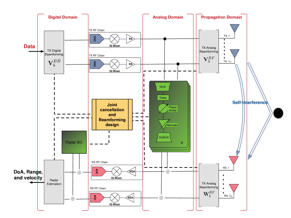
The SI channel between the RX and TX of an IBFD node comprises the direct path and any relevant multipath components. It can thus be modeled as a multipath channel with an exponential power delay profile, consisting of a quasi-static component due to the TX/RX antenna structures and a time-varying part related to the reflections from the surrounding environment [16]. In Fig. 1, an IBFD massive MIMO node including a partially-connected hybrid beamforming architecture at both the -antenna TX and -antenna RX sides that operates in the vicinity of targets is illustrated. Since, the DL signal from this node reflects back from the all passive radar targets present in the environment, the SI channel, , can be mathematically modeled as follows:
| (1) |
where (with ) is the complex amplitude of the echo received from the -th target (including path-loss and radar cross section), is the carrier frequency, is the symbol duration, and is the angular direction of the -th target. The two-way propagation delay due to the range of the target translates to a phase shift across the frequency and the Doppler shift , due to the moving velocity, translates to a phase shift across symbol duration. is the direct SI channel path between the node’s TX and RX. In addition, varies with antenna structure as and denote the mappings from the angle to the steering vectors of the RX and TX antennas, respectively. This SI characterization indicates that sensing information is completely contained in the SI signal. Note that, in IBFD communications, the SI signal has to be eliminated completely.
In IBFD systems deployed for simultaneous DL and UL communications, the SI signal needs to be cancelled since it contaminates the UL signal of interest. However, as shown in (1), this signal includes target sensing information. To this end, to enable FD-ISAC, it is necessary to admit reflections from the surrounding objects and avoid canceling the respective useful echo signals, while ensuring sufficient mitigation of the direct SI channel between RX and TX.
II-B From Self-Interference Cancellation to Self-Interference Management
For successful FD-ISAC systems, it is important to suppress the direct SI channel to ensure sufficient TX/RX isolation at the FD node’s RX side, while the reflections from the targets must be preserved, i.e., the channel . In IBFD MIMO transceivers, SI removal usually happens in three steps that can be distinguished based on their domain of operation (propagation, analog and digita domains), as shown in Fig. 1. When various domain SI suppression mechanisms are effectively implemented in the ISAC context, FD-ISAC communication can achieve success.
II-B1 Propagation Domain — Beamforming
This decreases SI power due to propagation losses, antenna element directionality, and/or beamforming usually achieved by MIMO. The beamforming controls the amplitude and phase coefficients of each antenna element to form beams, to maximize or minimize transmit/receive signal at specific points. In particular, the FD-ISAC transmit beamformer is optimized such that the target channel gain gets maximized while SI power leakage gets minimized. The receive beamformer/combiner rejects the remaining SI while providing a high beamforming gain in the direction of targets. Beamforming can be: 1) digital, where each antenna is connected to a dedicated Radio-Frequency (RF) chain providing maximum flexibility, 2) analog, where all antenna elements are connected to one RF chain for power efficiency, or 3) hybrid, where the reduced number of RF chain offers a trade-off between flexibility of beam-patterns and power cost. To highlight the differences between the FD-ISAC and IBFD beamformer/combiner, we depict the optimized analog TX beamformer and analog RX combiner for FD-ISAC in Figure 4. Note that TX gains at both sensing and communication directions are maximized. While the RX gain at the communication directions are attenuated. This marks a significant difference from IBFD MIMO SI cancellation, where the TX and RX gains are maximized only in communication directions.
II-B2 Analog Domain
The FD node can estimate the SI signal and subtract it from the received signal. Since its RX part knows the signal it is transmitting, it can extract its own information after correcting for the channel effect. The analog canceller usually consists of few (but not many) taps, each one including a line of fixed delay, variable phase shifter, and attenuator [17]. The taps are then connected via simple multiplexers (MUXs)/demultiplexers (DEMUXs) for efficient signal routing among the TX/RX RF chains. Two such reduced complexity hardware architectures for the analog canceler in IBFD MIMO were presented in [17]. The one architecture was based on analog taps and the other on Auxiliary (AUX) TXs. In contrast to the available analog cancellation architectures, the values for each tap or each AUX TX and the configuration of the multiplexers were jointly designed with the digital transceiver beamforming filters according to desired performance objectives. The former tap-based analog canceler architecture for SI cancellation was extended to the wideband case in [18]. Other hardware impairments for IBFD MIMO together with imperfect channel knowledge were studied in [19, 20]. It is noted that, for lower complexity analog SI cancellation, the focus can be on its line-of-sight component. After this cancellation, the residual SI signal needs to satisfy the RF saturation constraint at each reception unit.
II-B3 Digital Domain
This is similar to the analog domain, but performed on digital signals, i.e., after the Variable Gain Amplifier (VGA) and ADC. After beamforming and analog cancellation, the residual SI includes TX and RX in-phase and quadrature imbalances, nonlinear Power-Amplifier (PA) distortions, and the RX’s noise figure [21]. These nonlinear distortions can be cancelled using a combination of Maximum Likelihood (ML) methods, such as deep neural networks and transfer learning, as well as traditional model-based signal processing approaches[22, 23]. In the proposed FD-ISAC systems, the challenge is to distinguish between the echoes of targets and the direct SI signal which are coupling in the presence of noise. We expect that ML-based approaches for signal classification, such as the independent component analysis algorithm, can be beneficial due to the independent statistical characteristics of the two kinds of signals, i.e., moving targets versus static close reflectors. We believe that deep learning approach can track the angle parameters more accurately.
II-B4 Unified design for Massive MIMO
As the number of antenna elements increases, the interference signal leaking from the TX of the IBFD radio to its RX becomes more severe, thus, SI cancellation becomes more complex. To simplify the algorithmic design, reduce costs, and/or improve SI suppression, we can implement a unified IBFD MIMO architecture comprising A/D TX/RX beamforming, as well as A/D SI cancellation, which can be jointly designed for various performance objectives and complexity requirements [4]. This approach distributes the complexity where it is needed across the aforedescribed domains.
III FD-Enabled Simultaneous Communications and Sensing
The MIMO FD-ISAC node illustrated in Fig. 1 includes hybrid A/D TX/RX beamforming and A/D SI cancellation [4]. This architecture is capable to implement simultaneous sensing, in a monostatic fashion, and DL data transmission. Assume, for example, that it is deployed to serve one or more users in the DL direction, while, in parallel, it receives and processes the reflections of the DL signals by one or more radar targets within its vicinity, with the goal to estimate their parameters. The A/D TX/RX beamformers and the A/D SI cancellation units can be jointly optimized to meet ISAC-oriented objectives, as will be presented in the sequel. For example, an FD-based ISAC system may be designed to optimize DL communication performance, while guaranteeing a sensing-based performance metric, or vice versa. It can be also designed to jointly optimize sensing and communications, guaranteeing in parallel a certain pair of sensing and communications performance. In the next section, we will study the feasibility of FD-ISAC by evaluating its sensing range in the case of a mmWave massive MIMO setting.
III-A Sensing Range Case Study
In a mmWave massive MIMO FD-ISAC system, it is important to carefully adjust the transmit power at the FD node as well as the TX/RX beamforming gain to maintain stable sensing and communication links. It is, however, challenging to obtain precise sensing performance of the radar targets, since the received signal at the node’s RX unit travels twice the sensing range, given the monostatic nature of the system. Considering the high path-loss of mmWave channels, it is of paramount importance to design A/D TX/RX beamformers for our FD-ISAC systems with high beamforming gain to achieve the required a certain level of Signal-to-Interference-plus-Noise-Ratio (SINR) at the RX. Starting from (1), the complex amplitude of each -th target can be defined as follows:
| (2) |
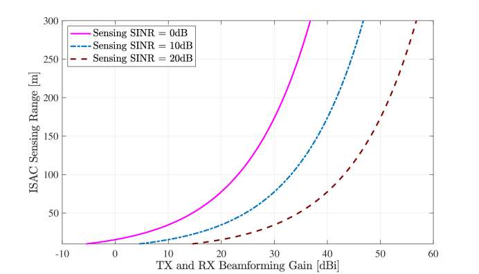
where , , , and represent respectively the range, path-loss exponent, Radar Cross Section (RCS), and the combined small-scale fading and shadowing loss of the -th target with denoting the operating wavelength. Now we consider a practical mmWave massive MIMO BS operating at GHz frequency with a bandwidth of MHz and a transmit power of dBm communicating with a DL user, while detecting multiple targets included in the sensing environment. In Fig. 2, we depict the sensing range of a MIMO FD-ISAC system with respect to the TX/RX beamforming gain required to achieve different SINR levels, considering a line-of-sight mmWave channel at GHz with path-loss exponent of and dB of combined small- and large-scale fading loss. We have assumed an automobile as the sensing target considering an RCS of or dBsm. As shown in the figure, approximately dBi of TX/RX beamforming gain is required to successfully detect a radar target at the range of m with a dB SINR value.
III-B Beamforming Design
We now consider the MIMO FD-ISAC node in Fig. 1 in the case that wishes to communicate with a -antenna user in the DL direction, while simultaneously sensing parameters related to a target placed in its vicinity. It is assumed that the TX and RX antenna elements are connected with TX and RX RF chains, respectively; this implies the general case of hybrid A/D beamforming. The node’s TX unit makes use of the precoding matrix and the analog beamforming matrix to process its -element symbol vector () before transmission, while the signal received at its RX unit can be processed in the analog domain via the combining matrix , and, in the digital domain, via the combining matrix . The DL transmission obeys the node’s total transmit power budget , i.e., . Finally, to deal with the SI signal, the considered the node deploys the analog- and digital-domain SIC matrices and , respectively.
We next focus on the joint optimization of the latter MIMO FD-ISAC system parameters to enable simultaneous DL data communications and target parameter estimation in the UL, the latter via the received reflections of the DL signal (and not via dedicated pilots used in conventional non-FD-based monostatic radar systems). We particularly consider the following optimization formulation as an example (excluding the optimization of the DL user parameters or equivalently assuming optimum combining at this receiving user):
where represents the represents the DL channel matrix and the remaining channel matrices , , and are defined in (1). In this example, yet parametric, MIMO FD-ISAC formulation, the design objective is the maximization of a DL communication metric (e.g., the achievable DL rate), which depends on the digital and analog beamformers and , respectively, while meeting a target parameter estimation objective that relates to the gain of the received signal reflection from the target (e.g., the received signal-to-noise ratio [12] or the opposite of the estimation Cramér-Rao bound [24]). As shown in constraint , the latter gain depends on the A/D SIC matrices and , the TX/RX beamformers , , , and , as well as the channel matrices and , and represents a threshold indicating the imposed desired sensing estimation accuracy. As for the other constraints in , describes the total transmit power budget at the MIMO FD-ISAC node and relates to the hardware capabilities and limitations of the analog canceller (see [17] for different forms of the analog cancellation matrix ). Finally, constraint includes the general vector function of the instantaneous residual SI appearing at the node’s RX antenna elements after analog SIC and before the RX RF chains, which needs to be upper bounded by the respective values in the vector to avoid the saturation of the ADCs at the latter RF chains. It is noted that the example ISAC framework in aims to optimize a communication metric while ensuring that a specific sensing performance threshold is met. Alternatively, those metrics could swap positions on ’s objective and constraints, i.e., focus on optimizing a sensing metric while guaranteeing a required communication level, or they can be both incorporated in the objective and have dedicated thresholds as constraints.
In MIMO FD-ISAC, the analog beamformer and combiner are common for both the radar and communication operations. However, digital beamforming in MIMO radar is somewhat different from that in communications and communication-centric ISAC. In particular, in MIMO radar, digital beamforming is applied in an indirect way compared to communications, by embedding the spatial processing into the transmitted waveform from the multiple antenna. This radar waveform is fed directly to the TX RF chains and the digital vector with the received signals at the outputs of the RX RF chains is used directly for sensing before another copy is processed via for detecting the UL communication symbols. This indicates that the spatial SI suppression becomes coupled with the MIMO waveform design, instead of being solely a joint cancellation and beamforming task as in conventional FD MIMO systems [17].
III-C Waveform Design
The transmitted waveform in FD-ISAC systems realizing simultaneous communications and sensing necessitates multi-objective optimization that addresses the trade-off between the two targeted functionalities. The existence of SI may affect both communications and sensing directly or at least indirectly as a compromise for the one functionality to reduce the SI effect on the other. The waveform can be optimized in time, frequency, and space as well as, ideally, in combinations of all of them, which, however, contributes in increased complexity. In this way, the symbol vector becomes a two-dimensional matrix (antennas time) or even a three-dimensional tensor (antennas time frequency) constituting the digital waveform. The former is obtained from the latter by splitting the time dimension in intervals and applying the discrete Fourier transform; this is the case in the Orthogonal Frequency-Division Multiplexing (OFDM) scheme.
Applying OFDM makes the MIMO waveform design more tractable. In [25], the -th Generation New Radio (5G NR) OFDM waveform was optimized for joint communications and sensing with FD base stations. The proposed system maintained multiple spatial streams for communication links over frequency-selective non-line-of-sight channels, while simultaneously transmits separate spatial radar streams to different sensing directions. The received reflections from the environment due to all transmitted streams were used for sensing employing radar processing techniques. The presented design also optimized the A/D TX precoding and analog RX combining (i.e., , , and ) so that inter- and intra-user interference as well as radar–communications interference are also canceled. This allowed to improve the detection probability and estimation errors of sensing via controlling the information transmission rate through the communication objective.
| Parameter | Value | Parameter | Value |
|---|---|---|---|
| Frequency | GHz | Number of TX/RX RF chains at node | |
| Bandwidth | MHz | Number of ULA antenna elements at node | |
| Number of OFDM symbols | Number of RX RF chains at node | ||
| Subcarrier spacing | kHz | Pathloss exponent | dBm |
| Active subcarrier | Combined small- and large scale fading loss | dBm | |
| OFDM symbol duration | s | RCS (automobile) | (dBsm) |
| Peak-to-Average Power Ratio | dB | SI channel pathloss | dB |
| Noise floor of nodes and | dBm | SI Channel -factor | dB |
| Noise Figure of nodes and | and dB | DFT codebook resolution | -bit |
IV Numerical Results and discussion
In this section, we present performance evaluation results for a massive MIMO FD-ISAC system operating at mmWave frequencies which communicates with a DL MIMO user through the 5G NR OFDM waveform while simultaneously sensing its surrounding environment that includes multiple passive targets.
Simulation Parameters: We consider the MIMO FD-ISAC node in Fig. 1 with antennas and a user with antenna elements that realizes fully digital combining in the DL direction. Each TX/RX RF chain at the FD node is connected to a Uniform Linear Array (ULA) capable of generating directive beams via a DFT codebook; it thus implements hybrid A/D TX/RX beamforming. The detailed parameters of the simulation are presented in Table. I. The FD-ISAC system is considered in a vehicular application with the goal to sense automobiles distributed within its vicinity with DoAs with . The range and relative velocity for each automotive radar target are selected randomly with a maximum range of m and maximum velocity of km/h (i.e., ). For the DL communication with node , out of targets were chosen randomly.
Complexity of the Analog SI Canceller: To hope for efficient estimation of the targets’ DoAs, the MIMO FD-ISAC node needs to efficiently cancel the strong SI signal. To this end, as also shown in Fig. 1, we consider both A/D SI cancellation to suppress this signal below the required radar SINR level. Since, for a practical mmWave setup with large number of antennas, it is infeasible to cancel the SI path from each of them, we implemented reduced complexity analog cancellation applied to the RX RF chain inputs, as shown in Fig. 1. Our aim was to utilize the smallest possible number of analog taps while avoiding RX RF chain saturation at node ; this is expressed in ’s constraint . Note that, for the considered MIMO FD-ISAC node with TX and RX RF chains, full-tap analog cancellation would need taps, whereas our analog canceller requires only analog taps (i.e., of the full-tap complexity). The residual SI was suppressed using a digital cancellation approach while maximizing the DL rate, as shown in with being that rate and the minimum SINR at the radar targets.
MIMO FD-ISAC Optimization: We have performed joint optimization of the beamforming and SI cancellation parameters of node (specifically, the A/D TX/RX beamformers , , , and , the MUX/DEMUXs in the -tap analog canceller described by matrix , and the digital SI cancellation matrix ), as described in , to enable simultaneous DL communications to node and precise sensing operation at the RX of node . For the latter functionality, we have considered as the sensing accuracy in ’s constraint the minimum SINR at the radar targets of dB.
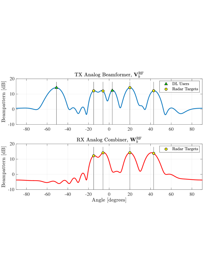
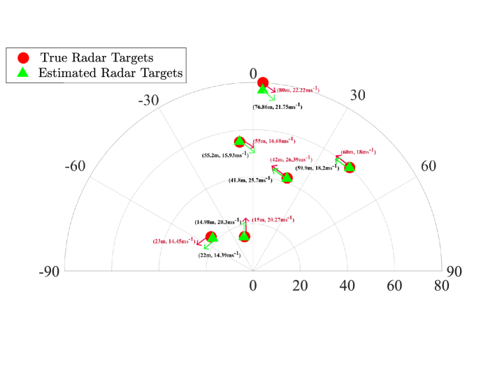
Sensing performance: The radar sensing performance of the proposed mmWave MIMO FD-ISAC system is illustrated in Fig. 3 for the transmit power dBm. In particular, the estimated DoAs, ranges, and velocities of all targets are demonstrated in contrast to their true values. The true target DoAs are indicated with green triangles and black letters for the range and velocity values, where the red circles and letters refer to the respective estimations. It is evident that the sensing parameters of all targets are successfully estimated with our joint optimization approach. Indicatively, for the targets placed up to m, the range and velocity estimation error is . However, for the target located at a distance of m, around m range and velocity estimation errors occur, which is mainly attributed to the larger path-loss. We also plot the Analog TX beamformer and Analog RX combiner in Figure 4. The TX gains at both communications and sensing directions are almost similar, showing that all streams are transmitted to both sets of directions. The RX gains at sensing directions are maximized while those at the communication directions are attenuated.
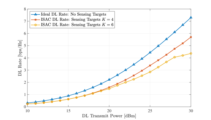
Achievable Rate Performance: The DL rate with the proposed MIMO FD-ISAC system and optimization framework in Fig. 3 for the case of a -element DL user is plotted versus in Fig. 5 for different numbers of targets in the environment. As observed, the achievable rate reduces with increasing values, indicating that a more demanding sensing constraint penalizes the communication performance. Specifically, the considered optimization allocates more DL beamforming resources towards the targets for better sensing accuracy. For example, for radar targets, bps/Hz more DL rate than the case of targets can be achieved.
V Future Research Directions
As previously discussed, ISAC in the explict form of simultaneous data transmission and monostatic sensing operations can be efficiently realized with appropriately designed FD MIMO systems. In this section, we present some of the key open challenges and their resulting research directions with MIMO FD-SAC.
Theoretical foundation: One of the key open areas ripe for research is the development of the theoretical foundations to understand the performance limits of supporting two functions simultaneously: communications and sensing. Past works have researched estimation-theoretic metrics for sensing in ISAC [26, 27, 28] and information-theoretic approaches to ISAC [29, 30], and more recently a degrees-of-freedom perspective. The diversity of ideas in analyzing joint communications and sensing systems demonstrates the range of perspective in the choice of metrics, which in turn means there is much to understand in the relationships between metrics and how they impact performance trade-offs. Continuing from the existing studies to incorporate IBFD operation and the resulting SI opens major new research questions as this adds a new dimension to the interplay between communications and sensing.
FD-ISAC modeling: The 3rd Generation Partnership Project (3GPP) Release recently launched channel modeling work for ISAC as well as new spectrum. The former activity aims to accurately model signal reflection and multi-path propagation, initially focusing on sensing of passive objects. MIMO FD-ISAC contributes the simultaneous transmission and reception feature, resulting in SI comprosing of possibly mixed near- and far-field channel terms. To this end, accurate, while tractable, channel and signal models capturing different settings and conditions are required. The models need to capture both the dominant effects accurately, e.g., the SI channel, non-linearities, and noise statistics, which may differ from those characterized previously for communications-only scenarios.
Physical-layer design: Given the channel, signal models and design objectives, there is significant room for innovation in the design of IBFD waveforms that can flexibly achieve different trade-off points incorporating the technical challenge of SI. For example, in [31], the authors derived a degree-of-freedom trade-off between wireless imaging and UL communications. Different points on the trade-off require different physical-layer designs. In addition, there exists a lot of room of MIMO FD-ISAC problem formulations and joint designs of all involved parameters (i.e., hybrid A/D TX/RX beamforming and A/D treatment of the SI signal). To this end, the trend towards extremely massive MIMO and beyond mmWave frequencies imposes challenges in the beamforming design, but also the opportunity to treat SI without dedicated cancellation units [13].
Hardware platforms: To validate the performance of advanced FD ISAC techniques at the mmWave frequency band, it is essential to develop dedicated hardware platform capable of hybrid A/D TX/RX beamforming with both analog and digital treatment of the SI signal. Very recently, a mmWave FD MIMO hardware prototype was presented in [32], demonstrating the ability to suppress interference in the spatial, analog, and digital domains, thereby significantly reducing residual SI to the noise floor. Additionally, the authors in [33] presented a mmWave half-duplex ISAC platform, showcasing its sensing and communication performance with multiple targets. However, there remains a need for a mmWave MIMO FD-ISAC hardware platform with simultaneous transmission and monostatic sensing capability.
Near-field operation: The use of Reconfigurable Intelligent Surfaces (RISs) [34] and metasurface-based antennas [35] at mmWaves and beyond (i.e., terahertz) are particularly suitable for sensing, thus, complementing typical sensing systems. In the former work, it was shown that placing an RIS in the near-field region of a MIMO FD-ISAC node can boost its ISAC capability when appropriately designing its parameters jointly with that of node’s. On the other hand, the latter work emphasized that a scalable MIMO FD-ISAC framework profits from near-field signal propagation. However, these works constitute preliminary investigations and mode sophisticated signal and channel models, new waveforms and related beamforming approaches will be needed. Especially, there is very limited work on MIMO FD-ISAC for near-field taking into account SI in both the waveform and beamforming designs.
VI Conclusion
In this article, we presented a generic MIMO FD-ISAC framework for spectrum-efficient simultaneous information transmission and monostatic sensing, elaborating upon its unique properties and associated SI challenges, as well as surveying state-of-the-art special cases. The framework’s fundamental difference in treating SI with respect to conventional FD MIMO systems used for simultaneous DL and UL communications was discussed, and future research directions with MIMO FD-ISAC systems and signal processing were presented. We believe that FD’s potential for ISAC will likely keep the research community occupied for many years to come, considering that there are a number of exciting open research topics.
References
- [1] 3GPP, “Ts 22.137 study on integrated sensing and communication, release 19,” 3GPP SA1, Tech. Rep., 2023.
- [2] ETSI, “Integration sensing and communication industry specification group,” ETSI, Tech. Rep., 2023.
- [3] F. Liu, Y. Cui, C. Masouros, J. Xu, T. X. Han, Y. C. Eldar, and S. Buzzi, “Integrated sensing and communications: Toward dual-functional wireless networks for 6G and beyond,” IEEE J. Sel. Areas Commun., vol. 40, no. 6, pp. 1728–1767, 2022.
- [4] G. C. Alexandropoulos, M. A. Islam, and B. Smida, “Full duplex massive MIMO architectures: Recent advances, applications, and future directions,” IEEE Veh. Technol. Mag., vol. 17, no. 4, pp. 83–91, Dec. 2022.
- [5] Z. He, W. Xu, H. Shen, D. W. K. Ng, Y. C. Eldar, and X. You, “Full-duplex communication for ISAC: Joint beamforming and power optimization,” IEEE Journal on Selected Areas in Communications, vol. 41, no. 9, pp. 2920–2936, 2023.
- [6] D. Korpi, M. Heino, C. Icheln, K. Haneda, and M. Valkama, “Compact inband full-duplex relays with beyond 100 db self-interference suppression: Enabling techniques and field measurements,” IEEE Transactions on Antennas and Propagation, vol. 65, no. 2, pp. 960–965, 2017.
- [7] B. Smida, R. Wichman, K. E. Kolodziej, H. A. Suraweera, T. Riihonen, and A. Sabharwal, “In-band full-duplex: The physical layer,” Proceedings of the IEEE, pp. 1–30, 2024.
- [8] B. Smida, A. Sabharwal, G. Fodor, G. C. Alexandropoulos, H. A. Suraweera, and C.-B. Chae, “Full-duplex wireless for 6G: Progress brings new opportunities and challenges,” IEEE J. Sel. Areas Commun., vol. 41, no. 9, pp. 2729–2750, Sep. 2023.
- [9] C. B. Barneto, S. D. Liyanaarachchi, T. Riihonen, M. Heino, L. Anttila, and M. Valkama, “Beamforming and waveform optimization for OFDM-based joint communications and sensing at mm-waves,” in Proc. IEEE Asilomar Signals Sys. Comp. Conf., Nov. 2020, pp. 895–899.
- [10] S. D. Liyanaarachchi, C. B. Barneto, T. Riihonen, M. Heino, and M. Valkama, “Joint multi-user communication and MIMO radar through full-duplex hybrid beamforming,” in Proc. IEEE Int. Symp. Joint Commun. & Sensing (JC&S), Feb. 2021, pp. 1–5.
- [11] M. A. Islam, G. C. Alexandropoulos, and B. Smida, “Simultaneous multi-user MIMO communications and multi-target tracking with full duplex radios,” in Proc. IEEE Global Commun. Conf. (GLOBECOM), Dec. 2022, pp. 1–6.
- [12] ——, “Integrated sensing and communication with millimeter wave full duplex hybrid beamforming,” in Proc. IEEE Intl. Conf. Commun. (ICC), May 2022, pp. 1–6.
- [13] I. Gavras, M. A. Islam, B. Smida, and G. C. Alexandropoulos, “Full duplex holographic MIMO for near-field integrated sensing and communications,” in European Signal Proces. Conf. (EUSIPCO), Helsinki, Finland, Sep. 2023.
- [14] M. Talha, B. Smida, G. C. Alexandropoulos, and M. A. Islam, “Multi-target two-way integrated sensing and communications with full duplex mimo radios,” in Asilomar Signals, Systems, Comp. Conf., Pacific Grove, USA, Nov. 2023.
- [15] M. A. Islam, G. C. Alexandropoulos, and B. Smida, “Direction-assisted beam management in full duplex millimeter wave massive MIMO systems,” in Proc. IEEE Global Commun. Conf. (GLOBECOM), Dec. 2021, pp. 1–6.
- [16] F. Chen, R. Morawski, and T. Le-Ngoc, “Self-interference channel characterization for wideband 2 × 2 mimo full-duplex transceivers using dual-polarized antennas,” IEEE Transactions on Antennas and Propagation, vol. 66, no. 4, pp. 1967–1976, 2018.
- [17] G. C. Alexandropoulos, “Low complexity full duplex MIMO systems: Analog canceler architectures, beamforming design, and future directions,” ITU J. Future Evolving Technol., vol. 2, no. 2, pp. 1–19, Dec. 2021.
- [18] M. A. Islam, G. C. Alexandropoulos, and B. Smida, “Joint analog and digital transceiver design for wideband full duplex MIMO systems,” IEEE Trans. Wireless Commun., vol. 21, no. 11, pp. 9729–9743, Nov. 2022.
- [19] ——, “A unified beamforming and A/D self-interference cancellation design for full duplex MIMO radios,” in Proc. IEEE PIMRC, Sep. 2019.
- [20] H. Iimori, G. Abreu, and G. C. Alexandropoulos, “MIMO beamforming schemes for hybrid SIC FD radios with imperfect hardware and CSI,” IEEE Trans. Wireless Commun., vol. 18, no. 10, pp. 4816–4830, Oct. 2019.
- [21] M. A. Islam and B. Smida, “A comprehensive self-interference model for single-antenna full-duplex communication systems,” in Proc. IEEE International Conference on Communications (ICC), May 2019, pp. 1–7.
- [22] K. Muranov, M. A. Islam, B. Smida, and N. Devroye, “On deep learning assisted self-interference estimation in a full-duplex relay link,” IEEE Wireless Commun. Lett., vol. 10, no. 12, pp. 2762–2766, 2021.
- [23] D. H. Kong, Y.-S. Kil, and S.-H. Kim, “Neural network aided digital self-interference cancellation for full-duplex communication over time-varying channels,” IEEE Trans. Veh. Technol., vol. 71, no. 6, pp. 6201–6213, 2022.
- [24] S. P. Chepuri, N. Shlezinger, F. Liu, G. C. Alexandropoulos, S. Buzzi, and Y. C. Eldar, “Integrated sensing and communications with reconfigurable intelligent surfaces,” IEEE Signal Process. Mag., vol. 40, no. 6, p. 41–62, Sep. 2023.
- [25] S. D. Liyanaarachchi, T. Riihonen, C. B. Barneto, and M. Valkama, “Joint MIMO communications and sensing with hybrid beamforming architecture and OFDM waveform optimization,” IEEE Transactions on Wireless Communications, 2023.
- [26] D. W. Bliss, “Cooperative radar and communications signaling: The estimation and information theory odd couple,” in IEEE Radar Conference, 2014.
- [27] B. Paul, A. R. Chiriyath, and D. W. Bliss, “Joint communications and radar performance bounds under continuous waveform optimization: The waveform awakens,” in IEEE Radar Conference, 2016.
- [28] C. Li, N. Raymondi, B. Xia, and A. Sabharwal, “”Outer Bounds for a Joint Communicating Radar (Comm-Radar): Three-node Uplink”,” IEEE Transactions on Communications, November 2021.
- [29] A. R. Chiriyath and D. W. Bliss, “Joint radar-communications performance bounds: Data versus estimation information rates,” in Proc. IEEE Military Communications Conference (MILCOM 2015), 2015, pp. 1491–1496.
- [30] Y. Xiong, F. Liu, Y. Cui, W. Yuan, T. X. Han, and G. Caire, “On the fundamental tradeoff of integrated sensing and communications under Gaussian channels,” IEEE Transactions on Information Theory, vol. 69, no. 9, pp. 5723–5751, 2023.
- [31] N. Mehrotra and A. Sabharwal, “Degrees of freedom analysis for multipath-assisted communication & sensing,” IEEE Journal on Selected Areas in Communications, vol. 40, no. 6, pp. 1768–1779, Jun. 2022.
- [32] B. Yu, C. Qian, J. Lee, S. Shao, Y. Shen, W. Pan, P. Lin, Z. Zhang, S. Kim, S. Hu et al., “Realizing high power full duplex in millimeter wave system: Design, prototype and results,” IEEE Journal on Selected Areas in Communications, vol. 41, no. 9, pp. 2893–2906, Jun. 2023.
- [33] T. M. Pham, R. Bomfin, A. Nimr, A. N. Barreto, P. Sen, and G. Fettweis, “Joint communications and sensing experiments using mmwave platforms,” in Proc. IEEE Workshop on Sig. Proc. Advan. in Wireless Commun. (SPAWC), Lucca, Italy, Sep. 2021, pp. 501–505.
- [34] C. K. Sheemar, G. C. Alexandropoulos, D. Slock, J. Querol, and S. Chatzinotas, “Full-duplex-enabled joint communications and sensing with reconfigurable intelligent surfaces,” in Proc. European Signal Process. Conf. (EUSIPCO), Helsinki, Finland, Sep. 2023, pp. 1–5.
- [35] I. Gavras and G. C. Alexandropoulos, “Joint near-field target tracking and communications with full duplex holographic MIMO,” in Proc. IEEE Int. Conf. Acoustics, Speech, Signal Process. (ICASSP), Seoul, South Korea, Apr. 2024, pp. 1–5.