Towards Error Budgeting for Superconducting Modular Quantum Architecture Designs
Abstract
This paper addresses frequency crowding constraints in modular quantum architecture design, focusing on the SNAIL-based quantum modules. Two key objectives are explored. First, we present physics-informed design constraints by describing a physical model for realizable gates within a SNAIL module and building a fidelity model using error budgeting derived from device characteristics. Second, we tackle the allocation problem by analyzing the impact of frequency crowding on gate fidelity as the radix of the module increases. We explore whether the gate fidelity can be preserved with a discrete set of qubit frequencies while adhering to defined separation thresholds. This work offers insights into novel quantum architectures and coupled optimization techniques to mitigate the effects of unstable noise and improve overall gate performance.
Index Terms:
superconducting quantum computing, hardware-software co-design, modular quantum architecture, spectator errorsI Introduction
Quantum circuits are executed on real quantum hardware by mapping gates to pulse controls targeting pairs of physically coupled qubits. For accurate gate execution, it is crucial to selectively control qubit-to-qubit coupling, ensuring that interactions occur only when needed [1, 2]. However, as qubit density increases, achieving high-fidelity gate operations becomes more challenging due to frequency crowding, which makes it harder to isolate specific interactions. Increased connectivity is necessary for scaling quantum systems to reduce data communication overhead from SWAP operations and to support topological error correction codes [3]. Modular architectures for superconducting quantum computing aim to address this challenge by balancing high connectivity with precise gate control, typically by limiting interactions to local neighborhoods of modules.
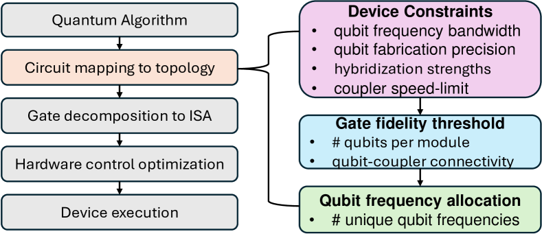
A particular example of a modular architecture is the SNAIL Corral [4, 5], a design that creates a local all-to-all topology within each SNAIL module, allowing for efficient qubit interactions. While previous research has focused on the Corral’s ability to reduce SWAP overheads and improve data movement efficiency, its impact on gate fidelity, particularly with respect to two-qubit gate frequency crowding, remains under explored. This work aims to investigate whether the Corral can be designed to meet fidelity requirements while managing frequency crowding in densely connected systems; by defining allowable error margins across hardware components, ensuring the system maintains uniquely addressable operations. By considering both simulated and experimentally determined constraints—such as frequency bandwidth, fabrication precision, coupler speed limits, and hybridization strengths—we can evaluate how each component contributes to overall gate error [6, 7, 8, 9]. Through error budgeting, we propose architectures that meet strict fidelity thresholds while accommodating the physical limitations of chip designs (see Fig. 1).
In this preliminary work, we explore how intra-module frequency separation can be maintained for varying numbers of qubits within a SNAIL module. The key question is: How many qubits can we couple to a SNAIL while retaining sufficient frequency separation to selectively drive iSWAP gates? Several prior works have focused on optimizing frequency allocation and device design with respect to crowding requirements and fabrication yields [10, 11, 12, 13, 14, 15]. However, our work is the first to explore the unique properties of three-wave mixing in SNAIL devices, which exhibit small static cross-Kerr between qubits. While qubits are weakly coupled directly, the dense all-to-all connectivity within a module introduces numerous spectator terms. The larger project will explore how these considerations scale with increasing qubit density and module count.
II SNAIL-Corral Architecture
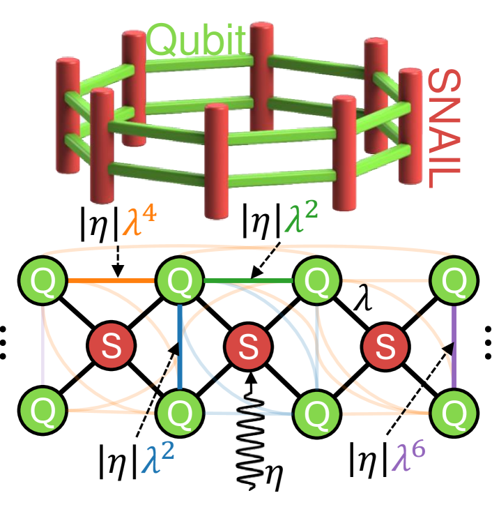
Each module of the ”Corral” architecture consists of four fixed-frequency transmon qubits, each coupled to a flux-tunable SNAIL. The transmons are superconducting resonators made from tantalum circuits with capacitively-shunted Josephson junctions (JJs) on sapphire chips, while the SNAIL is an asymmetric loop consisting of three to one JJs in parallel. Each qubit is capacitively coupled to a readout resonator for dispersive measurement, and each qubit and SNAIL is connected to a dedicated input line for state preparation and gate execution. Multi-qubit interactions occur by driving the SNAIL at specific frequencies, allowing qubits to interact via hybridization with the shared SNAIL mode.
The SNAIL-Corral architecture is designed to implement an iSWAP instruction set [17], efficiently realized through photon-conversion interactions. By driving the SNAIL at the frequency difference between two qubits, we enable these iSWAP-like gates. The system’s total Hamiltonian can be expressed as , where includes the linear terms, describes the nonlinearities, and represents the coupling between qubits and the SNAIL. The linear terms define the bare frequencies of the SNAIL and qubits:
| (1) |
where and represent the frequencies of the SNAIL and the qubits. The nonlinear terms for both the SNAIL and the qubits are given by:
| (2) |
where is the third-order non-linearity in the SNAIL, and represents the qubit anharmonicity. The coupling between qubits and the SNAIL is defined as:
| (3) |
where is the coupling strength between the SNAIL and the qubits. The SNAIL is designed such that qubit-qubit coupling is naturally turned off until selectively turned on via the SNAIL mode for gate execution. To simplify the analysis, we transform the system to the interaction frame using standard diagonalization and pump displacement transformations. The resulting effective Hamiltonian for a single module is:
| (4) |
Here, represents the dressed frequency in the re-diagonalized basis, and describes the hybridization between the SNAIL and qubits. is the square root of the effective pump photon number in the SNAIL mode, .
By transforming to the interaction frame [18], we can derive an effective Hamiltonian where each interaction term is modulated by a rate coefficient (influenced by the strength of the pump) and a phase factor that depends on how far off-resonance the interaction is from the pump’s frequency. When driving a specific interaction to resonance, the corresponding phase factor becomes zero, giving its full effect.
For off-resonant terms, the phase factor remains non-zero and oscillates, suppressing their contribution due to detuning. Although the Rotating-Wave Approximation (RWA) typically removes all terms except the target interaction, this assumes that the unwanted terms are sufficiently small and far enough off-resonance. A critical question we address is: how much do these off-resonant terms influence the system? We model these spectator interactions to determine the necessary degree of separation as a design constraint for future architectures.
III Defining separation constraints

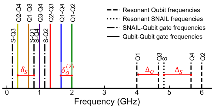
Our objective is to establish frequency separation constraints during frequency allocation and chip design to minimize unwanted interactions and ensure high-fidelity quantum gates. These constraints balance the strength of the target interaction with the suppression of off-resonant spectator terms (see Figure 3). The key frequency separations we define include: minimum qubit-qubit separation (), separation between qubit-qubit conversion frequencies (), separation between qubits and the SNAIL mode (), separation between SNAIL-qubit and qubit-qubit conversion frequencies (), and separation between conversion terms across different modules ().
Focusing on calibrating a two-qubit basis gate, such as iSWAP or , the total effective Hamiltonian for the target gate is given by Eq. 4, which can be written as .
| (5) |
In the ideal case, driving the pump on resonance, , isolates the desired interaction while suppressing all other terms.
| (6) |
The pulse duration, , required to achieve the gate depends on the specific unitary, e.g.
| (7) |
We leave as an independent variable and is uniquely determined by , reflecting physical limitations that constrain the coupler speed, and that decreases as the pump frequency moves further from resonance with the SNAIL mode. It’s worth noting that the chaotic breakdown of the SNAIL at higher pump powers is an active research area, so a proper lower-bound of is hard to describe [19].
To ensure robustness against worst-case scenarios, we apply two key modifications.
-
1.
Spectator terms introduce their own effective Rabi rates. In the worst-case scenario, the target gate (e.g., iSWAP) could align with an anti-node of a spectator interaction, effectively eliminating its effect. The detuning between the target and spectator terms is quantified by , where represents the detuning. This detuning reduces the impact of spectator interactions, but does not fully eliminate them in the worst-case scenario.
-
2.
As shown in Fig. 3, spectral crowding can occur around the target interaction from both sides. We correct the model for two spectator terms using a prefactor, which allows us to reduce the Hilbert space to only four qubits - rather than six - for tractable simulations while still capturing worst-case behavior.
This approach ensures that we account for the full spectral environment without over-complicating or over-fitting the model to some particular gate, where in the general case and thus are different for each qubit pair.
The total Hamiltonian, incorporating both the target and spectator interactions, is expressed as:
| (8) |
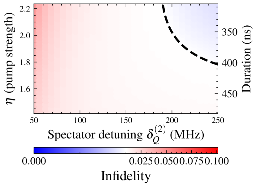
To account for incoherent errors, we solve the system’s time evolution using QuTiP’s Lindblad Master equation solver, incorporating amplitude damping channels to model qubit lifetimes. This produces the noisy time-evolution operator . The fidelity is then calculated using the 4-qubit average gate fidelity [20]:
| (9) |
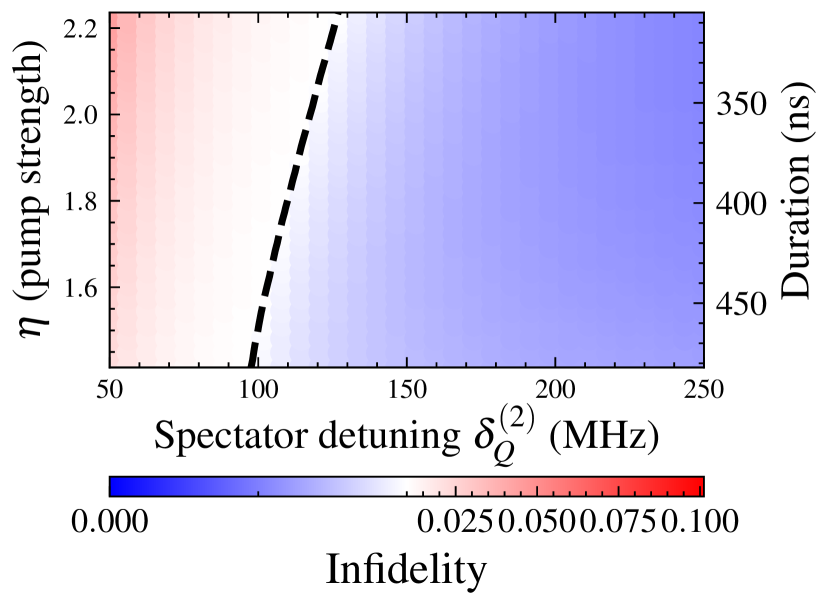
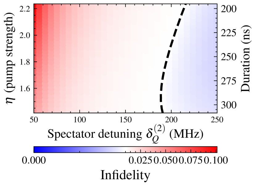
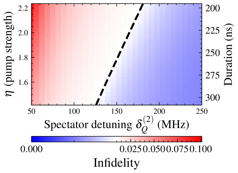
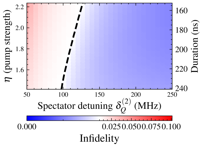
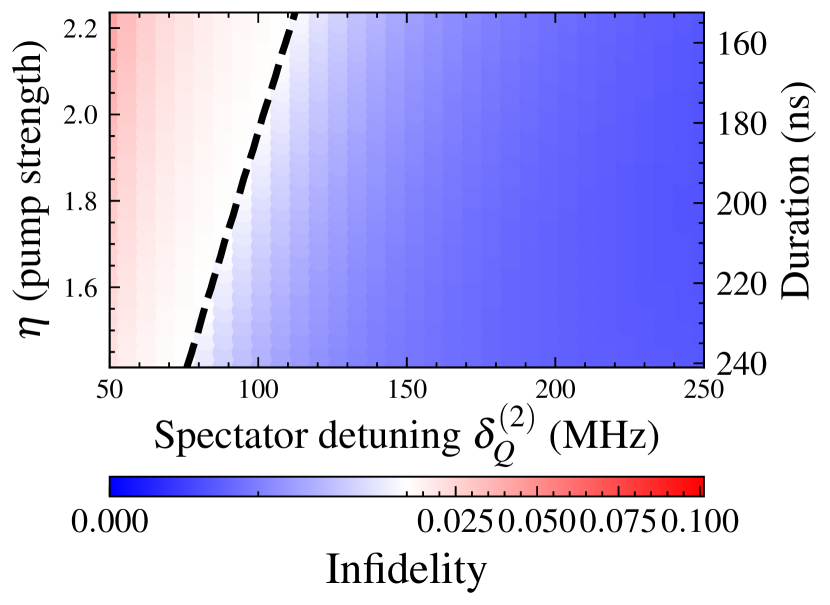
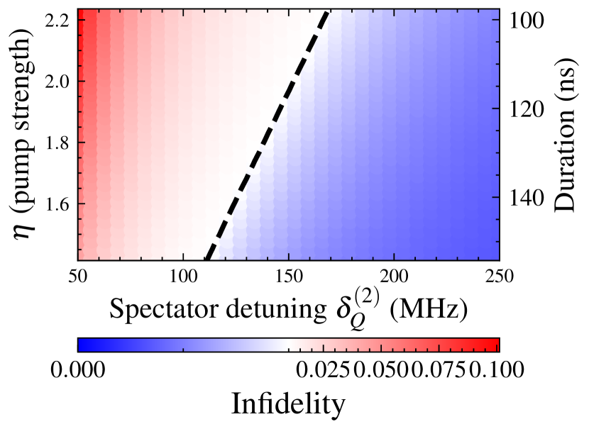
where is the ideal gate and is the noisy gate obtained from the Lindblad simulation. Finally, Figure 4 shows a sweep over pump strength and conversion separation, , marking where the fidelity threshold () is met.
IV Satisfying separation constraints
In our quantum architecture, the qubit frequencies () must be spaced by at least to avoid unwanted interactions, such as crosstalk, inaccuracies in single-qubit addressing, and fabrication tolerances. Additionally, sufficient separation is necessary to mitigate the effects of the AC Stark shift, where terms like in the effective Hamiltonian indirectly shift the energy levels of nearby qubits. This introduces errors in both single-qubit and two-qubit gate operations, reducing the available bandwidth for frequency allocation.
Similarly, the conversion frequencies between qubits,, must also be adequately spaced to ensure high-fidelity gate operations. To solve this frequency allocation problem, we use linear programming (LP) with CPLEX to maximize the conversion frequency separations () while ensuring a minimum qubit frequency separation () to handle both single-qubit addressing and AC Stark shift effects. This problem is analogous to classical frequency allocation challenges in communication systems, where frequencies must be spaced to reduce interference [21, 22, 23, 24]. The LP solver optimizes qubit frequency allocation within a defined bandwidth, e.g. 4 to 6 GHz, ensuring that qubits are spaced by at least . Conversion separations () are calculated for all qubit pairs, and the LP solver ensures that the difference between any two conversion frequencies meets the required separation. A binary search is employed to find the largest feasible while maintaining minimal computational overhead by avoiding ancillary variables in the solver [11].
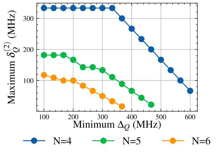
Fig. 5 shows the results of this approach, demonstrating how increasing the number of qubits in a module affects the achievable conversion frequency separations. For example, if qubits must be spaced at least 100 MHz apart, the solver shows that six qubits can achieve a maximum conversion separation of only 120 MHz, while a four-qubit configuration can achieve up to 330 MHz. This is because the number of conversion frequencies grows as . By adjusting the minimum qubit separation () along the x-axis in Fig. 5, we can better understand how much separation is needed to balance single-qubit . Table I summarizes the input and fit parameters for both iSWAP and gate configurations, along with the resulting qubit and conversion frequency separations.
| Gate | iSWAP | |
|---|---|---|
| Example parameters | ||
| Number of qubits | 4 | 4 |
| (MHz) | 60 | 60 |
| Bandwidth (GHz) | [4.0, 5.0] | [4.0, 6.0] |
| .1 | .08 | |
| (s) | 80 | 160 |
| Target fidelity | .99 | .99 |
| Min. (MHz) | 180 | 540 |
| Min. (MHz) | 150 | 120 |
| Discrete allocation | ||
| Qubits (GHz) | [4.00, 4.33, 4.81, 4.99] | [4.00, 4.78, 5.44, 5.98] |
| Conversion (GHz) | [.18, .33, .48, .66, .81, .99] | [.54, .66, .78, 1.2, 1.44, 1.98] |
V Conclusion
In this work, we analyzed the trade-offs between spectator interactions and qubit lifetimes when designing quantum gates in the SNAIL-Corral architecture. These systems have two regimes: one dominated by spectator noise and another constrained by qubit lifetime (). Stronger hybridization () enables faster gate operations but increases vulnerability to spectator noise, requiring careful parameter tuning to maintain high-fidelity gates.
Our model involves several simplifying assumptions. For instance, we omitted fast-rotating terms such as and , as well as higher-order combinations of both and , which could affect system dynamics. These aspects will be incorporated in future iterations. Additionally, we assumed negligible fourth-order non-linearity in the SNAIL and used ideal pulse shapes throughout. In practice, pulse shapes have finite spectral width, which should be accounted for to improve accuracy. Similarly, we assumed ideal transmon non-linearity and neglected Stark shifts, which will be addressed in future work.
Moving forward, we will extend this model to include more complex interactions, particularly between neighboring modules. Additionally, we will explore the impact of SWAP gates on overall circuit fidelity and investigate coherent error-cancellation techniques, such as compensatory pulses [9], to further mitigate spectator interactions. These efforts will contribute to optimizing the design of next-generation quantum architectures.
Acknowledgements
This work is partially supported by The Charles E. Kaufman Foundation of The Pittsburgh Foundation under New Initiative Award KA2022-129519 and by the Army Research Office under Grants No. W911NF2310253. The views and conclusions contained in this document are those of the authors and should be be interpreted as representing official policies, either expressed or implied, of the Army Research Office or the US Government. The US Government is authorized to reproduce and distribute reprints for government purposes not withstanding any copyright notation herein.
References
- [1] M. E. Beverland, P. Murali, M. Troyer, K. M. Svore, T. Hoefler, V. Kliuchnikov, G. H. Low, M. Soeken, A. Sundaram, and A. Vaschillo, “Assessing requirements to scale to practical quantum advantage,” Nov. 2022, arXiv:2211.07629 [quant-ph].
- [2] T. Tomesh and M. Martonosi, “Quantum Codesign,” MICRO, Sep. 2021.
- [3] P. Murali, N. M. Linke, M. Martonosi, A. J. Abhari, N. H. Nguyen, and C. H. Alderete, “Full-stack, real-system quantum computer studies: Architectural comparisons and design insights,” ISCA, 2019.
- [4] C. Zhou, P. Lu, M. Praquin, T.-C. Chien, R. Kaufman, X. Cao, M. Xia, R. S. K. Mong, W. Pfaff, D. Pekker, and M. Hatridge, “Realizing all-to-all couplings among detachable quantum modules using a microwave quantum state router,” Npj Quantum Inf., Jun. 2023.
- [5] E. McKinney, M. Xia, C. Zhou, P. Lu, M. Hatridge, and A. K. Jones, “Co-Designed Architectures for Modular Superconducting Quantum Computers,” in HPCA, 2023.
- [6] M. Brink, J. M. Chow, J. Hertzberg, E. Magesan, and S. Rosenblatt, “Device challenges for near term superconducting quantum processors: frequency collisions,” in IEDM, Dec. 2018.
- [7] V. Tripathi, M. Khezri, and A. N. Korotkov, “Operation and intrinsic error budget of a two-qubit cross-resonance gate,” Phys.Rev.A, Jul. 2019.
- [8] X. Ni, Z. Wang, R. Chao, and J. Chen, “Superconducting processor design optimization for quantum error correction performance,” Dec. 2023, arXiv:2312.04186 [quant-ph].
- [9] E. A. Sete, V. Tripathi, J. A. Valery, D. Lidar, and J. Y. Mutus, “Error budget of a parametric resonance entangling gate with a tunable coupler,” Phys.Rev.Appl., 2024.
- [10] G. Li, Y. Ding, and Y. Xie, “Towards efficient superconducting quantum processor architecture design,” in ASPLOS, 2020.
- [11] Y. Ding, P. Gokhale, S. F. Lin, R. Rines, T. Propson, and F. T. Chong, “Systematic crosstalk mitigation for superconducting qubits via frequency-aware compilation,” in MICRO, 2020.
- [12] K. N. Smith, G. S. Ravi, J. M. Baker, and F. T. Chong, “Scaling Superconducting Quantum Computers with Chiplet Architectures,” MICRO, Oct. 2022, publisher: IEEE.
- [13] A. Morvan, L. Chen, J. M. Larson, D. I. Santiago, and I. Siddiqi, “Optimizing frequency allocation for fixed-frequency superconducting quantum processors,” Phys.Rev.Res., Apr. 2022.
- [14] A. Osman, J. Fernández-Pendás, C. Warren, S. Kosen, M. Scigliuzzo, A. Frisk Kockum, G. Tancredi, A. Fadavi Roudsari, and J. Bylander, “Mitigation of frequency collisions in superconducting quantum processors,” Phys.Rev.Res., Oct. 2023.
- [15] J. Zhang, H. Wang, Q. Ding, J. Gu, R. Assouly, W. D. Oliver, S. Han, K. R. Brown, H. H. Li, and Y. Chen, “Qplacer: Frequency-Aware Component Placement for Superconducting Quantum Computers,” Jan. 2024, arXiv:2401.17450 [quant-ph].
- [16] N. C. Jones, R. Van Meter, A. G. Fowler, P. L. McMahon, J. Kim, T. D. Ladd, and Y. Yamamoto, “Layered architecture for quantum computing,” Phys.Rev.X, 2012, publisher: APS.
- [17] J. Chen, D. Ding, W. Gong, C. Huang, and Q. Ye, “One gate scheme to rule them all: Introducing a complex yet reduced instruction set for quantum computing,” in ASPLOS, 2024.
- [18] C. Zhou, “Superconducting Quantum Routers, Modules, Gates, and Measurements Based on Charge-pumped Parametric Interactions,” Ph.D. dissertation, University of Pittsburgh, Aug. 2023.
- [19] M. Xia, C. Zhou, C. Liu, P. Patel, X. Cao, P. Lu, B. Mesits, M. Mucci, D. Gorski, D. Pekker et al., “Fast superconducting qubit control with sub-harmonic drives,” arXiv preprint arXiv:2306.10162, 2023.
- [20] M. A. Nielsen, “A simple formula for the average gate fidelity of a quantum dynamical operation,” Phys. Lett. A, pp. 249–252, Oct. 2002, arXiv:quant-ph/0205035.
- [21] T. Park and C. Y. Lee, “Application of the graph coloring algorithm to the frequency assignment problem,” Journal of the Operations Research Society of Japan, 1996.
- [22] R. J. Waters, “Graph colouring and frequency assignment,” Ph.D. dissertation, University of Nottingham, 2005.
- [23] D. Orden, J. M. Gimenez-Guzman, I. Marsa-Maestre, and E. De la Hoz, “Spectrum Graph Coloring and Applications to Wi-Fi Channel Assignment,” Symmetry, Mar. 2018.
- [24] P. Jacko and S. Jendrol’, “Distance Coloring of the Hexagonal Lattice,” Discussiones Mathematicae Graph Theory, 2005.