Dynamically generated concatenated codes and their phase diagrams
Abstract
We formulate code concatenation as the action of a unitary quantum circuit on an expanding tree geometry and find that for certain classes of gates, applied identically at each node, a binary tree circuit encodes a single logical qubit with code distance that grows exponentially in the depth of the tree. When there is noise in the bulk or at the end of this encoding circuit, the system undergoes a phase transition between a coding phase, where an optimal decoder can successfully recover logical information, and non-coding phase. Leveraging the tree structure, we combine the formalism of “tensor enumerators” from quantum coding theory with standard recursive techniques for classical spin models on the Bethe lattice to explore these phases. In the presence of bulk errors, the coding phase is a type of spin glass, characterized by a distribution of failure probabilities. When the errors are heralded, the recursion relation is exactly solvable, giving us an analytic handle on the phase diagram.
In statistical physics, models defined on trees are often analytically tractable owing to the absence of loops, serving as a kind of infinite-dimensional limit [Gujrati1995, Baxter2007]. A classic example is the Ising/Potts model on the Bethe lattice, which, under fully polarized boundary conditions or free boundary conditions, exhibits a transition to a ferromagnetic phase [Chayes1986, Haggstrom1996, Wagner2000, Baxter2007] or spin glass phase [Higuchi1977, Chayes1986, Bleher1995, Ioffe1996, Mezard2006], respectively. The absence of loops has also enabled the construction of exactly solvable models of measurement-induced phase transitions in quantum circuits defined on an (expanding or contracting) tree geometry [Nahum2021, Feng2023, Ferte2024, Ferte2023, Feng2024]. But beyond being a setting for analytic tractability, the tree geometry also arises naturally in classical and quantum error correction, in the context of concatenated codes [Poulin2006, Yadavalli2023]. Code concatenation is a well-worn strategy for constructing high-distance codes out of small building blocks and underlies classic proofs of the threshold theorem [shor1996fault, aharonov1997, Knill1998, aharonov2008, Nielsen2010, Gottesman2024]. In this work we formulate code concatenation as the action of a unitary quantum circuit on an expanding tree geometry and study ”coding transitions” under various error models.
For certain classes of gates, applied identically at each node, the tree circuit encodes zero-rate codes with code distance that grows exponentially in the depth of the tree. When noise is applied to the leaves (“surface”) and/or branches (“bulk”) of the tree, these codes exhibit transitions between a “coding phase” at low error rates and “noncoding phase” at high error rates. The task of a maximum likelihood decoder is to determine, given a syndrome, the most likely logical class of a correction operator. Using the language of tensor enumerators [Cao2024, Cao2023], we relate this problem to that of classical broadcasting/reconstruction on trees [Kesten1966, Kesten1967, Evans2000, Mossel2003, Mossel2004, Mezard2006], with the bulk error rate playing the role of temperature, and the coding phase exhibiting the rich configurational landscape of a spin glass. When the code is a CSS code [Calderbank1996, Steane1996] subject to independent bit and phase flips, the connection to classical spin models is especially transparent, and the distribution of logical class probabilities across syndromes can be interpreted as a distribution of magnetizations at the root of the tree. We numerically simulate the recursion relation of this distribution to map out the phase diagram as a function of the bulk and surface error rates. When the errors are heralded, the recursion becomes exactly solvable, turning into a set of “flow equations” for the survival probability of logical information [Ferte2024].
Similar models of dynamically generated concatenated codes have been introduced independently in Ref. [Yadavalli2023]. The present work differs in several ways. First, we focus on the optimal decoder, formulated as a tensor network. Second, we emphasize the statistical mechanics interpretation of these error models, probing the spin glass structure in the coding phase and examining the scaling behavior using both numerical and analytical methods. \gsIn a forthcoming work, we also go beyond the “singletree” geometry to develop a fault-tolerant protocol [Sommers2025].
The paper proceeds as follows. In \autorefsect:setup we define and classify the encoding circuits using tensor enumerators. \autorefsect:methods discusses optimal decoding of Pauli errors, deriving a recursion relation for the distribution of logical class probabilities. \autorefsect:unheralded applies these methods to two models: depolarizing noise applied to the surface of a code with optimal distance scaling, and independent bit and phase flips applied to the “Bell tree” [Yadavalli2023], which generates a CSS code. Turning to heralded noise models, \autorefsect:herald presents the theory of heralded surface errors, while \autorefsect:bell offers a case study of the Bell tree with bulk and surface errors. We conclude in \autorefsect:conclude, reserving several details for the Supplement [supp-ref].
1 Binary tree encoding circuits
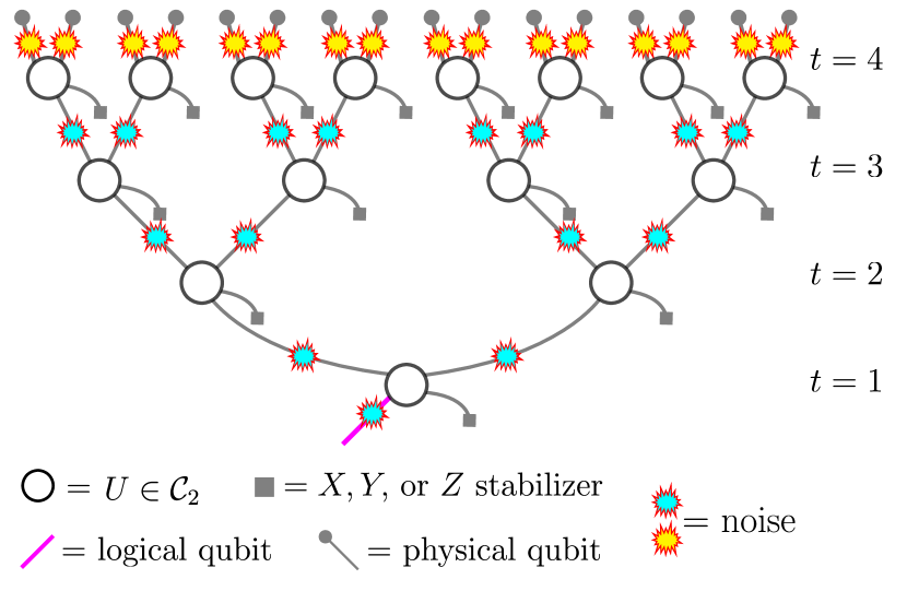
Consider a -ary tree, directed upwards as in \autoreffig:tree. To each node, we associate an -qubit gate, feeding in fresh qubits (by convention, on the right side). Thus this expanding circuit geometry generates an -qubit state, where is the tree depth, starting from one qubit (shown in purple) at the root of the tree. If we further impose that each gate is a Clifford gate, and all fresh qubits are initialized in a given stabilizer state (henceforth referred to as “stabilizer inputs”), this circuit encodes the root qubit (“logical input”) into an stabilizer code, where is the number of physical qubits, the number of logical qubits, and the code distance, the minimal weight of a logical operator, which depends on the depth. This encoding circuit contains all self-concatenated qubit codes as special cases, by taking each gate and stabilizer input to be identical; then each node defines the base code. While code concatenation is usually applied to a small code with distance , we find that even binary trees (), for which the local code necessarily has , can generate codes with distance that grows exponentially in the depth of the tree. These binary trees are the focus of this paper.
1.1 Tensor network formulation
Recursion relations for the code distance are obtained using the method of tensor weight enumerators introduced in Ref. [Cao2024], which we review briefly here and cast in a slightly different language.111Similar tensor network methods are presented in Refs. [Farrelly2021, Farrelly2022]. These tensors can be stitched together into more complex tensor networks [Ferris2014, Farrelly2021, Farrelly2022, Cao2022lego], making the construction far more general than what we present here.
The basic object for a binary tree is the rank-4 tensor describing a single node,
| (1) |
where is the stabilizer group of the “encoding state” [Cao2024] constructed by purifying both input legs with a reference, i.e., it is generated by
| (2) |
where is the two-qubit gate on that node. We use the convention that 222The ordering of and is nonstandard, but is chosen for consistency with the binary symplectic representation of stabilizer circuits [Gottesman2024], where . Then the operation in \autorefeq:pauliplus is just vector addition modulo 2. In other words, if the logical is encoded as . This is an unsigned version of the circuit tensor recently introduced in [Kukliansky2024].
From this tensor, we have the flexibility to leave any of the ”stabilizer legs” open, to construct a code with . Fixing one of these legs to be a stabilizer means contracting the above tensor with the vector , which we will denote by:
| (3) |
the circuit tensor for state preparation [Kukliansky2024].
For example, if we fix all the right legs to be stabilizers, then we obtain the rank-3 tensor
| (4) |
In words, if the logical coset of the associated code contains the operator .
A concrete example that figures prominently in the analysis below is obtained by taking the gate with stabilizer inputs:
| (5) |
Placing this tensor on every node of the tree encodes a generalized Shor code [ECZoo], and is referred to in Ref. [Yadavalli2023] as the Bell tree. Without the Hadamard gates, a binary tree composed of only CNOT gates would generate a concatenated repetition code, encoding a classical bit into the codewords and . The repetition code has an optimal threshold against bit flip errors, but it is a poor quantum code, providing no protection against phase flips. In contrast, with the added Hadamard gates, the Bell tree alternatively concatenates a “bit flip” repetition code and a “phase flip” repetition code, thus defending against both types of errors.
1.2 Vector enumerators
Viewing the tree circuit as the encoding circuit of a logical fed into the root, we can associate to this code a four-component vector, the complete balanced vector enumerator [Cao2024], whose component enumerates the elements of the logical class:
| (6) |
where is the stabilizer group of the -qubit encoding state of the code, and is an element of the -qubit Pauli group modulo phases. Here we have adopted the notation of Ref. [Cao2024] in defining
| (7) |
where is the number of Pauli ’s in the Pauli string .
The complete vector enumerator can be obtained from a network of tensors [\autorefeq:Rtilde] as follows. Place the vector
| (8) |
on each leaf of the tree: these are the “physical qubits.” Then let denote the operation:
| (9) |
where means ”equal up to a phase”. Finally, let
| (10) |
The tensors correspond to inserting Pauli errors in the circuit, in a sense that will be made clear below.
In this notation, the vector enumerator of a depth tree is