Abstract
Detection of scintillation light in noble liquid detectors is necessary for identifying neutrino interaction candidates from beam, astrophysical, or solar sources. Large monolithic detectors typically have highly efficient detectors, like photomultipliers, mounted outside their electric field. This option is not available for modular detectors that wish to maximize their active volume. The ArgonCube light readout system detectors (ArCLights) are large-area thin wavelength shifting (WLS) panels that can operate in highly proximate modular detectors and within the electric field. The WLS plastic forming the bulk structure of the ArCLight has Tetraphenyl Butadiene (TPB) and sheets of dichroic mirror layered across its surface. It is coupled to a set of six silicon photomultipliers (SiPMs). This publication compares TPB coating techniques for large surface areas and describes quality control methods for large scale production.
keywords:
noble liquid scintillation light, detector development1 \issuenum1 \articlenumber0 \datereceived \daterevised \dateaccepted \datepublished \hreflinkhttps://doi.org/ \TitleImprovement and Characterisation of the ArCLight Large Area Dielectric Light Detector for Liquid Argon TPCs \TitleCitationImprovement and Characterisation of the ArCLight Large Area Dielectric Light Detector for Liquid Argon TPCs \AuthorJonas Bürgi1\orcidH, Livio Calivers1\orcidA, Richard Diurba1\orcidE, Fabian Frieden1, Anja Gauch1\orcidG, Laura Francesca Iacob1,†, Igor Kreslo1,‡\orcidD, Jan Kunzmann1\orcidF, Saba Parsa1\orcidC, Michele Weber1*\orcidB \AuthorNamesJonas Bürgi, Livio Calivers, Richard Diurba, Fabian Frieden, Anja Gauch, Laura Francesca Iacob, Igor Kreslo, Jan Kunzmann, Saba Parsa, Michele Weber \AuthorCitationBürgi, J et. al. \corresCorrespondence: michele.weber@unibe.ch \firstnoteNow at Università degli Studi di Perugia, 06124 Perugia PG, Italy \secondnoteNow at Moscow Institute of Physics and Technology, Dolgoprudny, Russia
1 Introduction
Long-baseline neutrino detectors rely on large-area photon detectors such as photomultipliers to detect Cherenkov or scintillation light from neutrino interactions. Examples of such detectors are the Hyper-Kamiokande Abe et al. (2018) and the Deep Underground Neutrino Experiment (DUNE) Abi et al. (2020) Far Detector modules. These detectors expect to measure no more than a few neutrinos a day. Nevertheless, future neutrino beams, like Fermilab’s PIP-II beam, will provide () of neutrino interactions for the liquid argon near detector Abud et al. (2021) per beam spill. Multiple light flashes belonging to different neutrino interactions could coincide within the long drift time of the charge signals and lead to an overlap of signals from different interactions. Modularization of the detector can isolate the distinct scintillation light signals induced by the many neutrino scatterings per spill in optically segmented volumes. However, the light detectors must have a small volume to minimize dead space between modules Amsler et al. (2015).
The ArgonCube light readout system (ArCLight) addresses the need for dielectric, large-area, small-footprint photon detectors. The dielectric design of the ArCLight structure allows it to be placed directly in a detector’s high-voltage drift field. Accordingly, DUNE has selected ArCLight for the DUNE Liquid Argon Near Detector (ND-LAr). Inspired by the ARAPUCA light trap Machado and Segreto (2016), ArCLight follows a similar principle: light is trapped and travels through a wavelength shifting (WLS) layer towards an array of six SiPMs coupled along one face of the WLS plate Auger et al. (2018).
This publication outlines the production methods used to produce ArCLights in large quantities and the quality control methods utilized to ensure that high-performance ArCLights can operate in modular detectors. The ND-LAr detector comprises 35 modules, each measuring approximately in width, in length, and in height. Each module contains two time projection chambers with an anode plane on the opposing walls. Fifty percent of the area of the side walls is covered by ArCLights. The remainder of each side wall is filled by an alternate light trap design based on wavelength-shifting fibers that span the surface of a polycarbonate back panel. The fiber based modules are called Light Collection Modules (LCMs) and provide an increased photon detection efficiency Anfimov et al. (2020).
The ArCLights to be deployed in the DUNE ND-LAr are wide, long and thick. For the studies in this publication, ArCLights with a reduced length of were used. These were constructed for an ND-LAr demonstrator detector, the ArgonCube 22 Demonstrator Abud et al. (2021). The ArgonCube 22 Demonstrator is a modular liquid argon detector containing four reduced-size prototypes of DUNE ND-LAr modules assembled in a two-by-two arrangement.
In Section 2, an overview of the ArCLight technology as a light trap for vacuum ultraviolet (VUV) photons is provided. Section 3 describes two different Tetraphenyl Butadiene (TPB) coating techniques. Section 4 describes the manufacturing process for ArCLights, and Section 5 details the analysis performed on the quality control test data of the produced ArCLights.
2 Overview of ArCLight Concept
Liquid argon emits scintillation light in a narrow band centered around with different decay times ranging from a few to when excited by a passing-through charged particle. The time profile consists of a fast and slow component due to the decay of singlet and triplet excited states of the argon dimers Hitachi et al. (1983). This light gets collected by large-area light traps, which are read out by photosensitive devices. Given that VUV photons quickly get absorbed in materials commonly used in light traps, wavelength-shifting techniques are required to convert them to a suitable wavelength for propagation inside the bulk material.
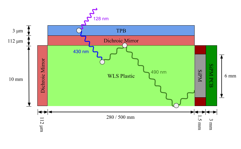
The design of the ArCLight incorporates two stages of wavelength shifting. The bulk material of the ArCLight consists of a thick plate of WLS material EJ280, produced by Eljen Technology, that is covered by a thick dichroic mirror (DF-PA Chill foil), produced by 3M. The foil is coated with a layer of Tetraphenyl Butadiene (TPB) of approximately thickness to shift the VUV into blue (peak at ) photons. The photons enter the WLS plate and are shifted into the green (peak at ). Due to the dichroic mirror, the photons are trapped inside the structure. The dichroic mirror covers three narrow edges of the WLS plate to improve the trapping efficiency. On the uncovered readout edge of the WLS plate, six Hamamatsu S13360-6050CS SiPMs with a \qtyproduct6 x 6\milli sensitive area are mounted in fixed intervals to collect the trapped photons. Figure 1 shows a conceptual diagram of the ArCLight.
One particular requirement for the ArCLight design is that is can be placed along the drift electric field of the TPC, therefore the light trap is made of dielectric materials. The readout edge with SiPMs and electronics is located at the anode plane of the TPC and, therefore, is not subject to a varying potential.
3 Comparison of TPB coating techniques
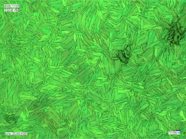
A key stage in the production of ArCLights is the application of its TPB coating. In early prototypes of the ArCLight, TPB was deposited by airbrush. For this purpose, TPB was dissolved in toluene with polystyrene, then sprayed directly on the dichroic mirror. This method leads to a structure of TPB crystals embedded in polystyrene. It improves the robustness of the TPB layer, helping avoid dissolution in liquid argon over years of operation, as has been observed previously Asaadi et al. (2019). However, inspecting the TPB layer under an optical microscope shows that the coverage factor of TPB is relatively poor using the airbrush method. Figure 2 shows the microscope view of the TPB coverage.

As stated in Benson et al. (2018), vacuum evaporation deposition can achieve a higher TPB coverage. In evaporation deposition, the substrate coating, TPB, is vaporized in vacuum using a heat source. The flux of the vaporized substrate eventually hits the target surface, where it condensates. An evaporation chamber designed and optimised for coating the large surface of an ArCLight was developed and tested.
The resulting crystal layer is shown in Figure 2. The evaporation method, described in Section 4, creates a much more uniform crystal layer with approximately full surface coverage. The two coating methods were compared in a TPC setup using two identical ArCLights with different TPB layers. By comparing the expected and measured light yield from cosmic muon tracks in the TPC, the Photon Detection Efficiency (PDE) was extracted. The evaporation coating showed an improvement in efficiency by a factor of two compared to the airbrush method Calivers (2021).
4 Production of ArCLight
The TPB coating is performed in a vacuum chamber from Pfeiffer Vacuum, KBH DN 750. Figure 3 shows a picture of the vacuum chamber and associated instrumentation used to coat the ArCLights. The first step for the production of ArCLights is to laminate the dichroic mirror on a \qtyproduct32 x 34\centi aluminum plate using 3M 467MP adhesive transfer-tape. The aluminum plate is then placed with the dichroic mirror facing downwards on the structure inside the vacuum chamber, such that the dichroic mirror has a distance of to the heating table. To keep the sample at room temperature, a water-cooled plate is attached on top of the aluminum plate. A tray is filled with uniformly distributed TPB and placed on the custom-made heating table. The heating table consists of 24 resistive heating elements of type RND 15550 3R9 F mounted on an aluminum plate. The setup has temperature sensors on the heating table, the dichroic mirror, and the water-cooled plate.
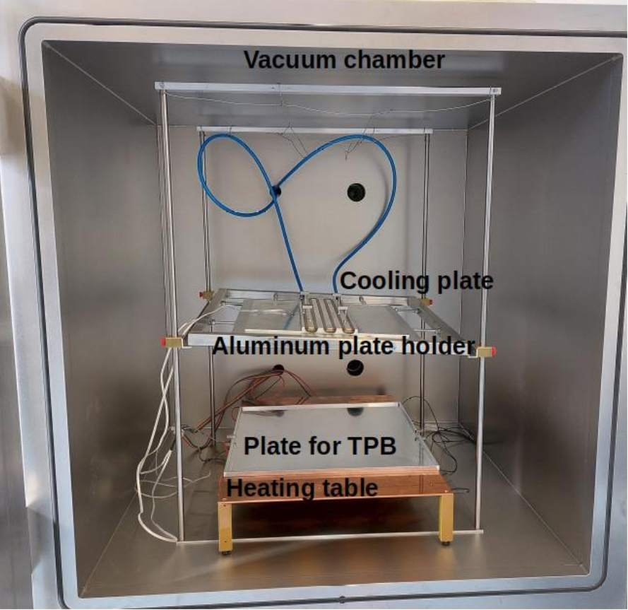
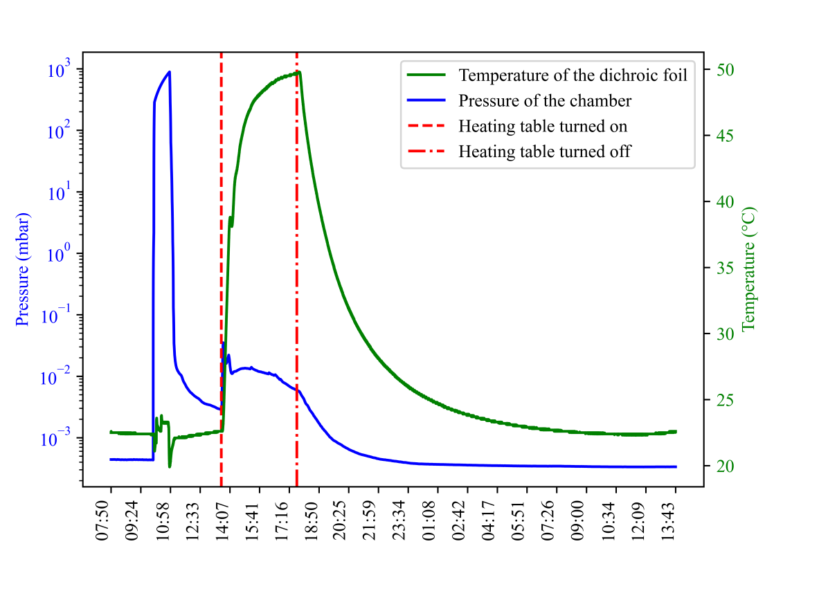
First, the vacuum chamber is evacuated using a roughing pump and a turbo-molecular pump to start evaporation. The heating table switches on once the chamber reached a pressure less than . The heating table is connected to a PID controller (ACS-13A-R/M), which keeps the TPB tray temperature constant at by interrupting the circuit.
The full coating process, which includes evacuation and heating, takes approximately four hours. Figure 4 shows the pressure and temperature of components during the TPB evaporation process. At the end of the cycle, the heater is turned off. After the chamber cools down, the chamber is pressurized, and the coated foil is removed.
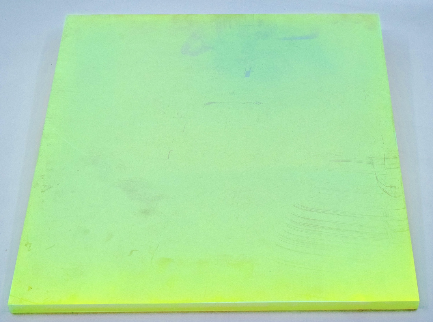
The coated dichroic mirror is removed from the aluminum plate and glued to the clean WLS EJ280 tile. The EJ280 material is cleaned with soap and water and dried with a cotton cloth. On three narrow faces of the EJ280 tile, strips of dichroic mirror are attached. Six SiPMs are fixed on the remaining narrow face of the ArCLight. They are placed on a Printed Circuit Board (PCB), which is mounted using threads in the EJ280 material, ensuring direct contact between the SiPMs and the light trap. The area around the SiPMs is covered with a dielectric mirror foil. Figure 5 shows a bare WLS tile EJ280 on the left and a WLS tile with TPB-coated foil on the right.

5 Quality control and analysis of produced ArCLights
Twenty-two units were produced following the procedure described in Section 4. Once the ArCLight is produced, two quality assurance tests are conducted to ensure its performance. The first test is a qualitative optical inspection. The coating structure and TPB crystals are observed with an optical microscope (Keyence, VHX-7000).

Two different types of crystals of TPB, referred to as irregular and elongated, are identified. Figure 6 shows an example of each. The irregular crystals are small pad-like crystals that create an irregular distribution over the area. The elongated crystals are filament-like crystals that are bunch-wise oriented.
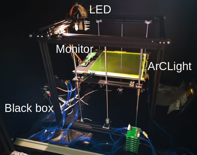
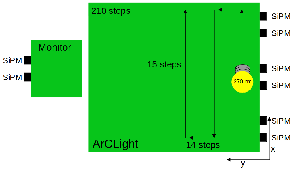
The second test quantitatively compares the light yield for all ArCLights in the production batch. This test uses a pulsed LED that emits light with a wavelength of . The LED is mounted on a robotic arm that can move across the surface of the ArCLight. The test measures the light yield at 210 different LED positions to scan the ability of light collection across the surface of the ArCLight. The LED is kept at a fixed vertical distance from the ArCLight surface during the scan. The measurement is performed in a black box, which shields the setup from stray light. The black box and the scanning setup are shown in Figure 7. In Figure 8, a cartoon of the scanning process is sketched.
The LED pulse triggers the light readout system, which records the waveforms from the six SiPMs. The waveforms are integrated over the pulse width and calibrated by measuring response waveforms of single photoelectrons (p.e.). For each position of the LED and on each SiPM, 15,000 waveforms are collected, and the mean number of p.e. per SiPM is extracted. Figure 9 shows the result of a high-resolution scan.
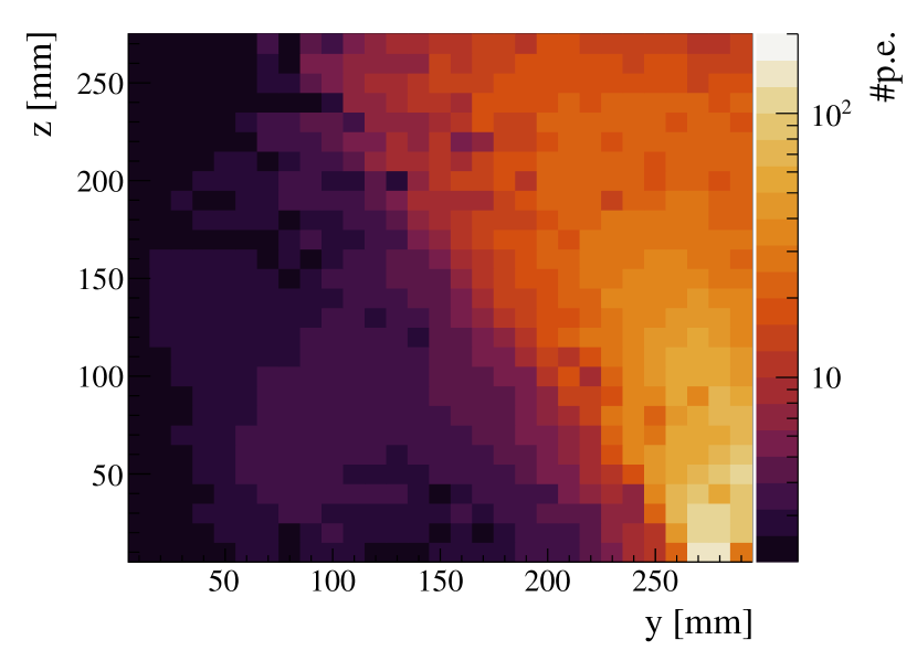
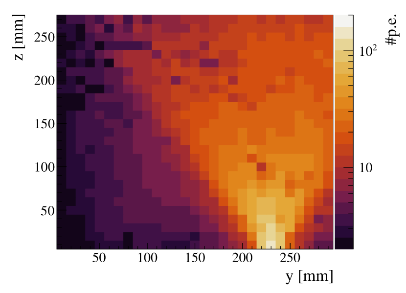
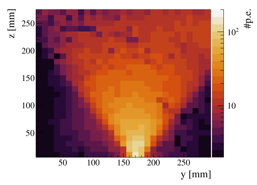
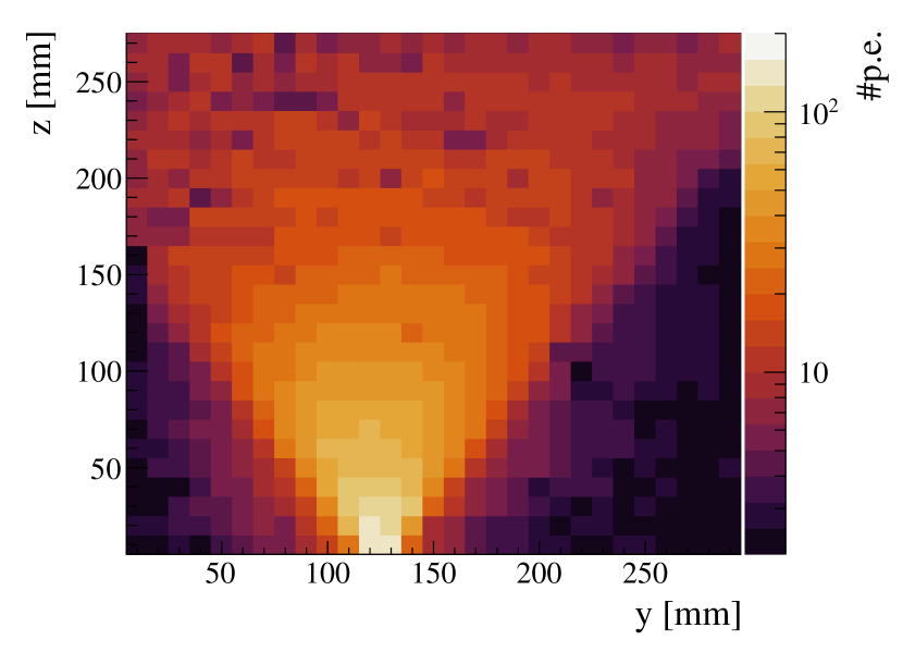
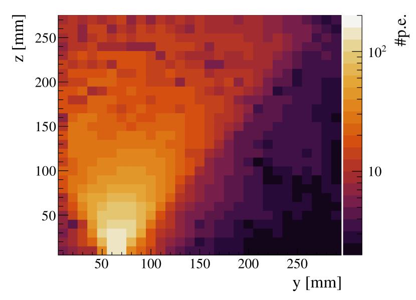
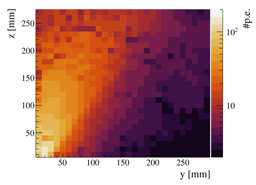
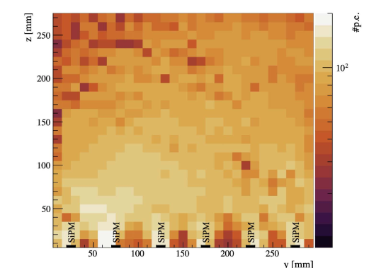
For a performance comparison, the mean of the collected p.e. of the six SiPMs are summed for each position of the LED. The sums of the collected light per position illustrates the number of captured p.e. for each SiPM at every position. As shown in Figure 10, the amount of the collected light mainly depends on the distance to the SiPMs. Additionally, observed reductions in light yield could indicate regions of poor TPB coverage. Two additional SiPMs fixed on the scanning table monitor the LED and measure its light yield stability. They enable to correct for intensity variations. During a scan, the monitoring SiPMs are repeatedly illuminated by the LED. The measured number of p.e. is equalized and the number of p.e. on the ArCLight SiPMs is subsequently adjusted for each point.
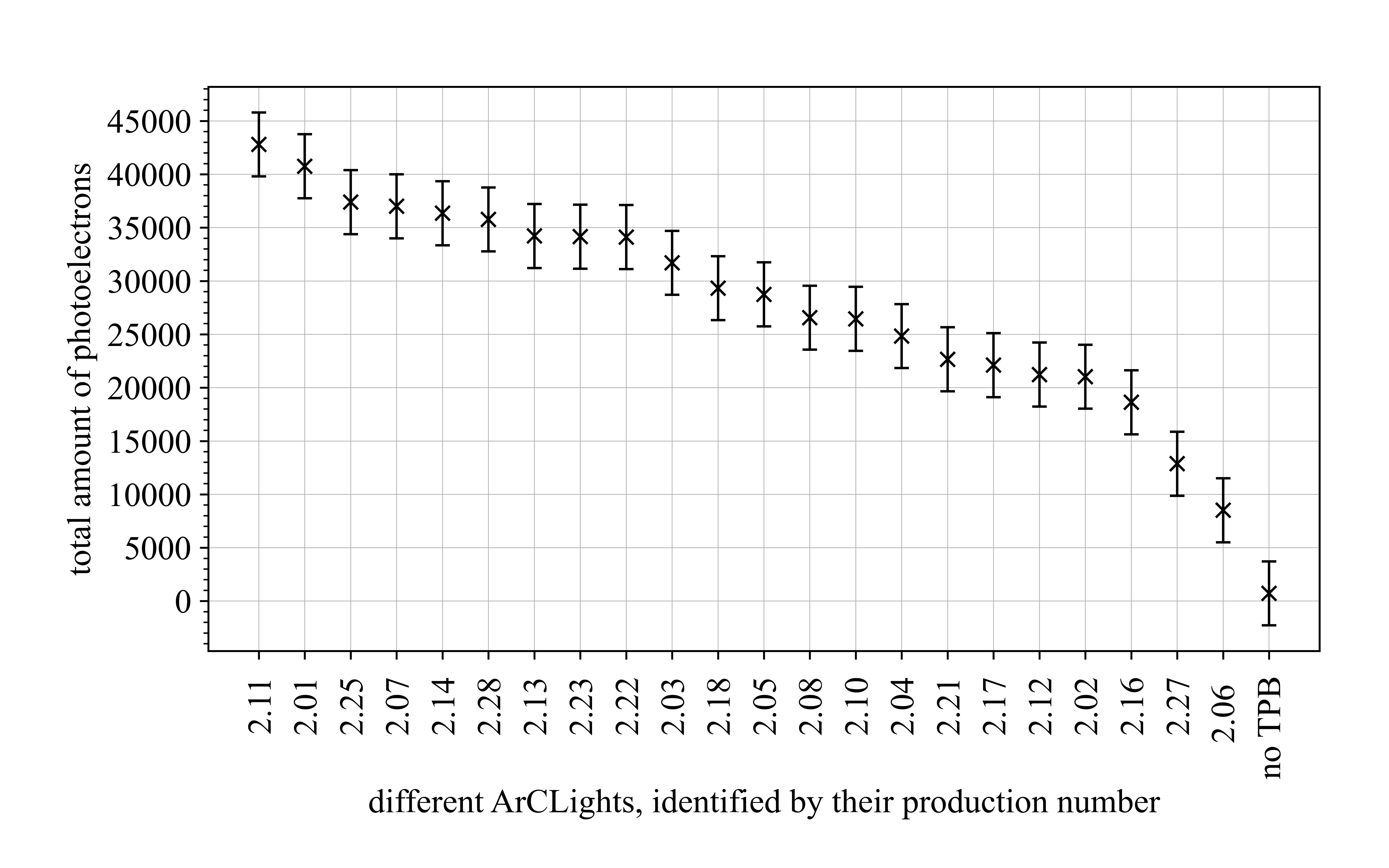
The total light yield across all positions scanned on the ArCLight is used as a metric to compare different ArCLights. The comparison of the different ArCLights produced in the production batch for the ArgonCube 22 Demonstrator is shown in Figure 11. The uncertainties on the measurements are set at 3000 p.e., a conservative estimate based on the maximum disagreement observed between scans of the same ArCLight. The ArCLight with the worst light collection is the ArCLight without any TPB coating, which was analysed for comparison. This demonstrates the necessity of TPB in order to detect any photons in the UV range. Figure 11 shows a large spread of performance for different ArCLights, highlighting the importance of stabilising and understanding the production parameters as much as possible in the future productions. Specific differences in the ratio of irregular to elongated crystals covering the ArCLights are observed.
Twenty ArCLights were selected with similar and consistent TPB coverage and inspected with a microscope. For each ArCLight, at least five randomly distributed \qtyproduct150 x 180\micro surface regions were evaluated with respect to their predominant crystal shapes. These were then categorized by the fraction of elongated and irregular crystals observed. While no ArClight was found to have a majority of elongated crystals, two categorizations emerged: ArCLights with a ratio of 1:1 irregular to elongated crystals, and ArCLights with a ratio of over 2:1 irregular to elongated crystals. For each ArClight, the total amount of p.e. was determined using the scanning technique described earlier in this section. The average of the total light collected for the two categories revealed an increase of in light yield for the sample of ArCLights with a higher fraction of irregular crystals.
6 Conclusions
Significant advancements have been made to enhance performance and design of the ArCLight system. The transition from manually brushing the TPB layer onto the surface to evaporating it within a vacuum chamber has notably increased the coverage and uniformity of TPB distribution. This change improved the photon detection efficiency by approximately a factor of two.
The performance variations for different ArCLights in the scan suggest a potential instability in production conditions. The scans show that the TPB layer and the crystal shape are crucial factors for the performance of the ArCLights. Nevertheless, quality assurance assessments confirm that ArCLights meet the performance requirements for their intended use in DUNE ND-LAr and the 22 Demonstrator. The production chain is adaptable for scaling up to full-size tiles. Future improvements are envisioned to maximize detector performance and ensure ongoing advancements in ArCLight technology.
Acknowledgements.
The research is funded by grant 200021-169045 of Swiss National Science Foundation and by Canton of Bern, Switzerland. The study is supported by the Mechanic and Electric Workshop at the Laboratory for High Energy Physics, Universität Bern, as well as the Albert Einstein Center for Fundamental Physics, Universität Bern. \conflictsofinterestThe authors declare no conflicts of interest. \appendixtitlesno \appendixstart \reftitleReferencesReferences
- Abe et al. (2018) Abe, K.; et al. Hyper-Kamiokande Design Report 2018. [arXiv:physics.ins-det/1805.04163].
- Abi et al. (2020) Abi, B.; et al. Deep Underground Neutrino Experiment (DUNE), Far Detector Technical Design Report, Volume I Introduction to DUNE. JINST 2020, 15, T08008, [arXiv:physics.ins-det/2002.02967]. https://doi.org/10.1088/1748-0221/15/08/T08008.
- Abud et al. (2021) Abud, A.A.; Abi, B.; Acciarri, R.; Acero, M.A.; Adamov, G.; Adams, D.; Adinolfi, M.; Aduszkiewicz, A.; Ahmad, Z.; Ahmed, J.; et al. Deep Underground Neutrino Experiment (DUNE) Near Detector Conceptual Design Report. Instruments 2021, 5. https://doi.org/10.3390/instruments5040031.
- Amsler et al. (2015) Amsler, C.; Arbelo, Y.; Asaadi, J.; Auger, M.; Barbato, F.; Bay, F.; Bishai, M.; Bleiner, D.; Borgschulte, A.; Bremer, J.; et al. ArgonCube: a novel, fully-modular approach for the realization of large-mass liquid argon TPC neutrino detectors. Technical report, CERN, Geneva, 2015. Available online: http://cds.cern.ch/record/1993255.
- Machado and Segreto (2016) Machado, A.A.; Segreto, E. ARAPUCA a new device for liquid argon scintillation light detection. JINST 2016, 11, C02004. https://doi.org/10.1088/1748-0221/11/02/C02004.
- Auger et al. (2018) Auger, M.; Chen, Y.; Ereditato, A.; Goeldi, D.; Kreslo, I.; Lorca, D.; Luethi, M.; Mettler, T.; Sinclair, J.; Weber, M. ArCLight—A Compact Dielectric Large-Area Photon Detector. Instruments 2018, 2. https://doi.org/10.3390/instruments2010003.
- Anfimov et al. (2020) Anfimov, N.; et al. Development of the Light Collection Module for the Liquid Argon Time Projection Chamber (LArTPC). JINST 2020, 15, C07022. https://doi.org/10.1088/1748-0221/15/07/C07022.
- Hitachi et al. (1983) Hitachi, A.; Takahashi, T.; Funayama, N.; Masuda, K.; Kikuchi, J.; Doke, T. Effect of ionization density on the time dependence of luminescence from liquid argon and xenon. Physical Review B 1983, 27, 5279. https://doi.org/10.1103/PhysRevB.27.5279.
- Asaadi et al. (2019) Asaadi, J.; Jones, B.J.P.; Tripathi, A.; Parmaksiz, I.; Sullivan, H.; Williams, Z.G.R. Emanation and bulk fluorescence in liquid argon from tetraphenyl butadiene wavelength shifting coatings. JINST 2019, 14, P02021, [arXiv:physics.ins-det/1804.00011]. https://doi.org/10.1088/1748-0221/14/02/P02021.
- Benson et al. (2018) Benson, C.; Gann, G.D.O.; Gehman, V. Measurements of the intrinsic quantum efficiency and absorption length of tetraphenyl butadiene thin films in the vacuum ultraviolet regime. Eur. Phys. J. C 2018, 78, 329. https://doi.org/10.1140/epjc/s10052-018-5807-z.
- Calivers (2021) Calivers, L. Development and Characterisation of a Novel Light Detector: ArCLight. Master’s thesis, University of Bern, 2021. Available online: https://cds.cern.ch/record/2886536.