Improved Electron-Nuclear Quantum Gates for Spin Sensing and Control
Abstract
The ability to sense and control nuclear spins near solid-state defects might enable a range of quantum technologies. Dynamically Decoupled Radio-Frequency (DDRF) control offers a high degree of design flexibility and long electron-spin coherence times. However, previous studies considered simplified models and little is known about optimal gate design and fundamental limits. Here, we develop a generalised DDRF framework that has important implications for spin sensing and control. Our analytical model, which we corroborate by experiments on a single NV center in diamond, reveals the mechanisms that govern the selectivity of gates and their effective Rabi frequencies, and enables flexible detuned gate designs. We apply these insights to show a potential 60x sensitivity enhancement for detecting weakly coupled spins and to study the optimisation of quantum gates in multi-qubit registers. These results advance the understanding for a broad class of gates and provide a toolbox for application-specific design, enabling improved quantum control and sensing.
I Introduction
Sensing and controlling nuclear spins in the vicinity of optically active solid-state defects, such as the nitrogen vacancy (NV) center in diamond, has opened up various opportunities in the fields of quantum sensing and quantum information processing [1, 2, 3, 4]. Sensing nuclear spins outside the host crystal might bring chemical structure determination to the single-molecule level [1, 3, 5, 6]. More strongly coupled nuclear spins inside the host material can be used for quantum information processing, for which advances in the number of available qubits [7], in gate fidelities [8, 9] and in the possibility to connect systems via an optical interface [2, 10] have led to proof-of-principle demonstrations of increasing complexity [11, 3, 4].
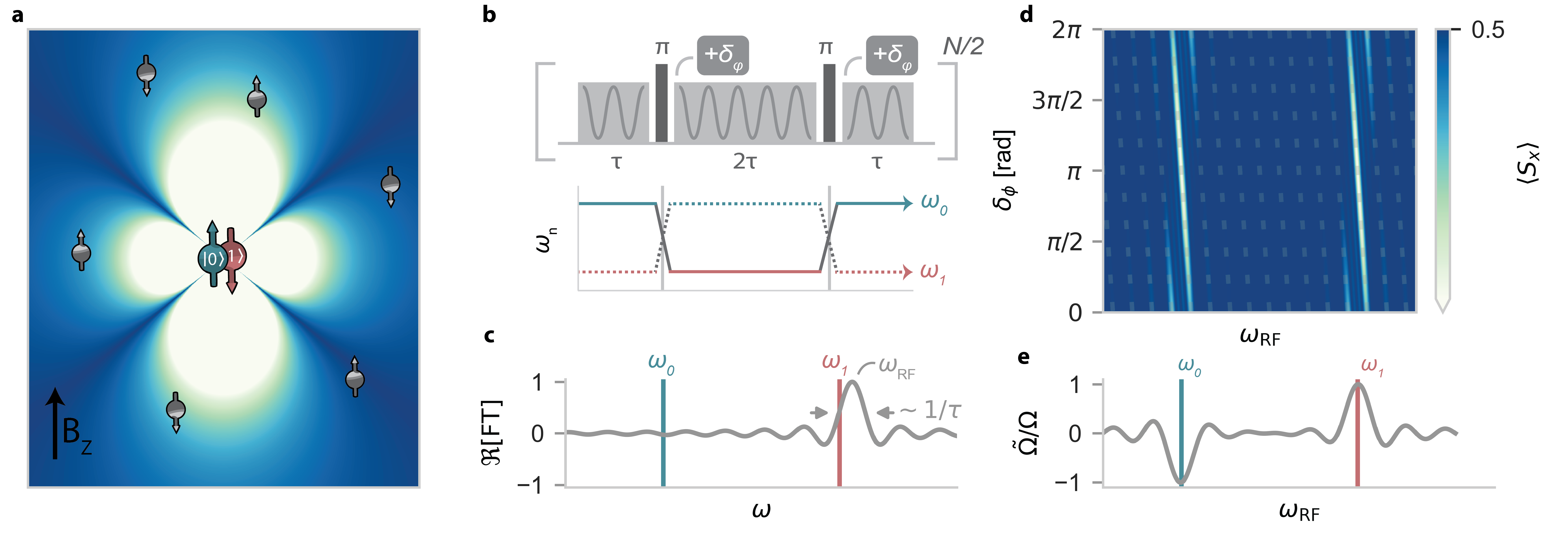
Central to these developments has been the ability to sense and control nuclear spins using the defect’s electron spin through the hyperfine interaction [12, 13, 14, 15, 16, 17]. In particular, dynamical decoupling (DD) protocols have been used to detect nuclear magnetic resonance signals [18, 19] and allow for selective, universal nuclear spin control [20]. However, traditional DD sensing and control is not effective for certain electron-nuclear geometries and provides only limited (temporal) flexibility in spin control. Alternatively, the recently developed DDRF sequence [14], which combines DD with radio-frequency (RF) pulses, unlocks additional sensing and control directions (Fig. 1a) and offers increased flexibility for gate optimisation[9]. These advantages have helped enable the sensing of large nuclear spin clusters [3, 7] and extended the number of nuclear spins available to defect centers for information processing [14, 21, 22].
In this work, we introduce a generalised version of the DDRF framework, enhancing the sequence’s performance for nuclear sensing and control, as well as revealing important limitations. We derive analytical expressions that give a more complete description of the electron-nuclear dynamics compared to previous work [14] and verify their predictions experimentally using a single NV center and its surrounding 13C nuclear spins. Based on these insights, we modify the DDRF sequence to enhance the effective electron-nuclear interaction strength and mitigate crosstalk of quantum gates. These results have applications in the field of nano-NMR [6, 1, 3] and provide a comprehensive toolbox for designing quantum gates in multi-qubit electron-nuclear spin systems [21, 14].
II Decoherence-protected radio-frequency quantum gates
We first describe the DDRF gates. Compared to the original description [14], we present a generalized framework, explicitly including the off-resonant driving of nuclear-spin transitions. We will show that this refinement has important implications for the performance of quantum gates and sensing sequences implemented with DDRF control.
We consider an electronic spin interacting with a number of nuclear spins via a hyperfine interaction (see Fig. 1a). To retain generality for defects with different spin numbers [23, 24, 25, 26, 27], we assume two electron spin states are selected to use as a qubit and describe these as a pseudo spin- system spanned by and .
The main challenge for electron-nuclear gates in such systems is that the electron interacts with all nuclear spins, as well as other noise sources, leading to decoherence and crosstalk [14, 13, 28]. Hence, a well-designed electron-nuclear two-qubit gate or sensing sequence aims to realize a conditional interaction with a selected (group of) target spin(s), while protecting electron coherence by decoupling all other interactions and noise sources.
The DDRF gate consists of a sequence of dynamical decoupling (DD) pulses on the electron spin, interleaved with RF pulses that drive the nuclear spin transitions, as illustrated in Fig. 1b. As a concrete example, we consider sequences of the form , with the number of -pulses and the interpulse delay. The DD sequence aims to decouple the electron spin from the surrounding spins and magnetic field fluctuations, extending the electron-spin coherence [15]. The interleaved RF pulses aim to manipulate selected nuclear spins and to re-couple them to the electron spin [14].
In the frame of the electron energy splitting, the Hamiltonian for the electron spin and a single nuclear spin is [14] (Appendix B):
| (1) |
where is the mean nuclear-spin frequency, with and the nuclear spin precession frequencies for electron-spin states or , respectively. is the strength of the electron-nuclear hyperfine interaction, which can be expressed in terms of a parallel and perpendicular component and [12] (Appendix B). and are the electronic and nuclear spin- operators, respectively. Note that we neglect the anisotropy of the hyperfine (). While this interaction can create complex dynamics and can be used for qubit control [20, 12], the effects can be minimized by applying strong magnetic fields () and setting the interpulse delay to a multiple of the nuclear spin Larmor period [14].
The RF pulses selectively drive nuclear spins, recoupling them to the electron-spin. In the interaction picture, the Hamiltonian during the RF pulses for a single nuclear spin is (in the rotating frame at the RF frequency ):
| (2) |
with and the detunings between the nuclear-spin transition frequencies and the RF frequency, the phase and the Rabi frequency of the (bare) RF drive.
Because the frequencies and differ by , an RF pulse will generally cause a different nuclear-spin evolution for the and electron states, enabling the construction of conditional two-qubit gates. Similarly, other spins with undergo a different evolution, introducing an element of selectivity between different nuclear spins. Previous work [14] assumed that resonant RF driving () combined with resulted in negligible driving during the electron state, thus neglecting that part of the driving term in . Below, we show that this term cannot generally be neglected due to the broad effective bandwidth of the short RF pulses (small ) in the DDRF sequence.
To ensure that the DDRF sequence generates the desired gate, the phase of each RF pulse must be set so that the pulses result in a constructive build-up of rotations on the nuclear spin. This equates to following the phase evolution of the nuclear spin in the frame of the RF frequency. In the decoupling sequence, this is achieved by incrementing the phase of the next RF pulse by a phase-angle every time a decoupling -pulse is applied on the electron spin (Fig. 1b).
In one DDRF block (), the nuclear spin accumulates a total phase of (up to a correction for the AC-Stark shift, see Appendix D). Moreover, by adding a phase shift with each decoupling pulse, the direction of the RF drive is inverted synchronous to the flipping of the electron spin state, creating a conditional electron-nuclear interaction. This gives rise to a resonance condition, satisfied by setting a single-pulse phase increment:
| (3) |
up to multiples of . The dependence of the mean precession frequency during the gate, (, on the electron-nuclear hyperfine interaction means that this resonance condition provides an additional mechanism for selectivity between different nuclear spins. The dependence is generally strong if the average of the electron spin projection used is non-zero (for example, for the and states of the NV spin-1). Importantly, Eq. 3 constitutes a generalisation of the phase-increment resonance considered in previous work (restricted to ) [14].
To quantify the strength of the conditional interaction, we evaluate the unitary of the total DDRF sequence under the Hamiltonian in Eq. 2, setting the phase increment to Eq. 3. We assume that the rotation due to an individual RF pulse is small (), which is typical for DDRF gates, because the gate’s total rotation angle is broken up into pieces. In this limit, the evolution can be described by a conditional rotation of the nuclear spin (Supplementary Note 2):
| (4) |
with an effective Rabi frequency given by:
| (5) |
where , with the axis set by the phase of the first RF pulse and the sinc function is defined as: . Note that previous work neglected off-resonant driving, where and , so that Eq. 5 reduces to [14].
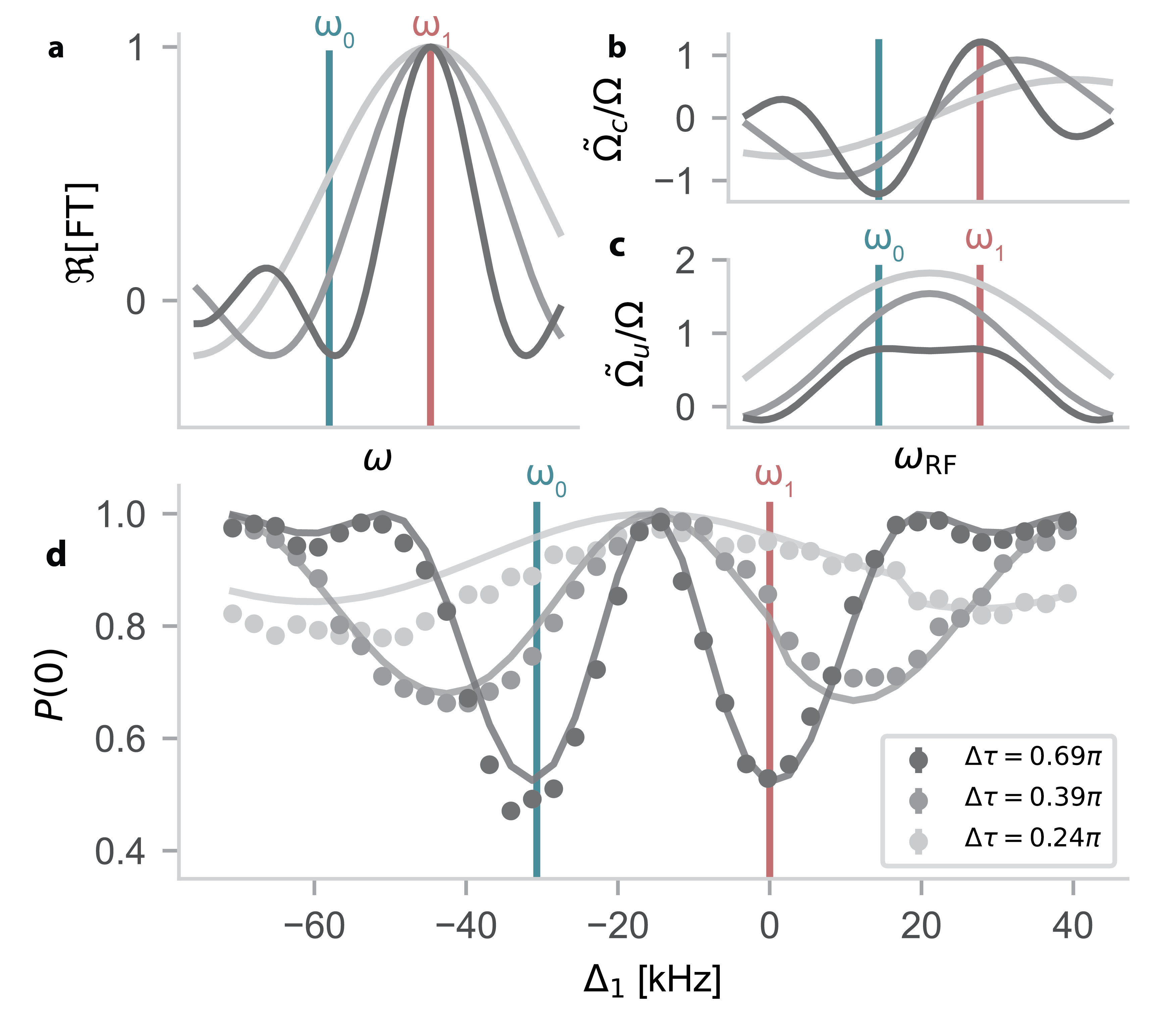
Setting in Eq. 4 results in a fully entangling gate, equivalent to a CNOT up to single qubit rotations. Furthermore, Eq. 5 shows that such a gate can be constructed in the neighborhood of the and frequencies, over a bandwidth given by (see Figs. 1 c-e). Note that this can be understood as the result of evaluating the Fourier transform of an individual RF pulse (applied at ) at the nuclear-spin transitions and , and that the bandwidth is much larger than would be expected from power broadening due to .
In the next section, we experimentally verify Eqs. 3 and 5 by performing DDRF spectroscopy on a single NV center in diamond. We observe sharp resonances corresponding to single 13C nuclear spins, following the prediction of Eq. 3, (analogous to Fig. 1d). We probe the interaction strength at these resonances by constructing detuned electron-nuclear gates (), and observe a reduction of the effective Rabi frequency, as predicted by Eq. 5. Next, we investigate the weak-coupling regime (), for which Eq. 5 ultimately limits gate fidelity, due to an inherent trade-off between effective interaction strength (higher for large ) and electron decoherence (worse for large ) (section IV). Finally, we apply these insights to two applications: maximising the sensitivity for detecting a single nuclear spin (Section V) and optimising the DDRF gate for qubit control under the effects of crosstalk and decoherence present in nuclear-spin quantum registers (Section VI).
III Generalised DDRF spectroscopy
Even though all results in this work can be generalised to other electron-nuclear spin systems, in the following we will consider in particular the electron-spin subspace of the NV center in diamond (electronic spin-1) and its surrounding 13C nuclear spins. The main difference with other electron spin systems is how depends on the hyperfine couplings. See Beukers et al. [29] for experiments and simulation on an electron spin-1/2 system (the tin-vacancy center in diamond), for which the dependence of vanishes up to second order corrections due to the perpendicular hyperfine component [30].
All experimental results are obtained from a single NV center in a natural abundance (1.1%) 13C diamond sample at cryogenic temperatures (4 K), with a 189.1 mT magnetic field aligned along the NV symmetry axis denoted (Appendix A). At this field, the nuclear quantisation axis is approximately parallel to the -axis, and only contributes as a frequency shift (Appendix B).
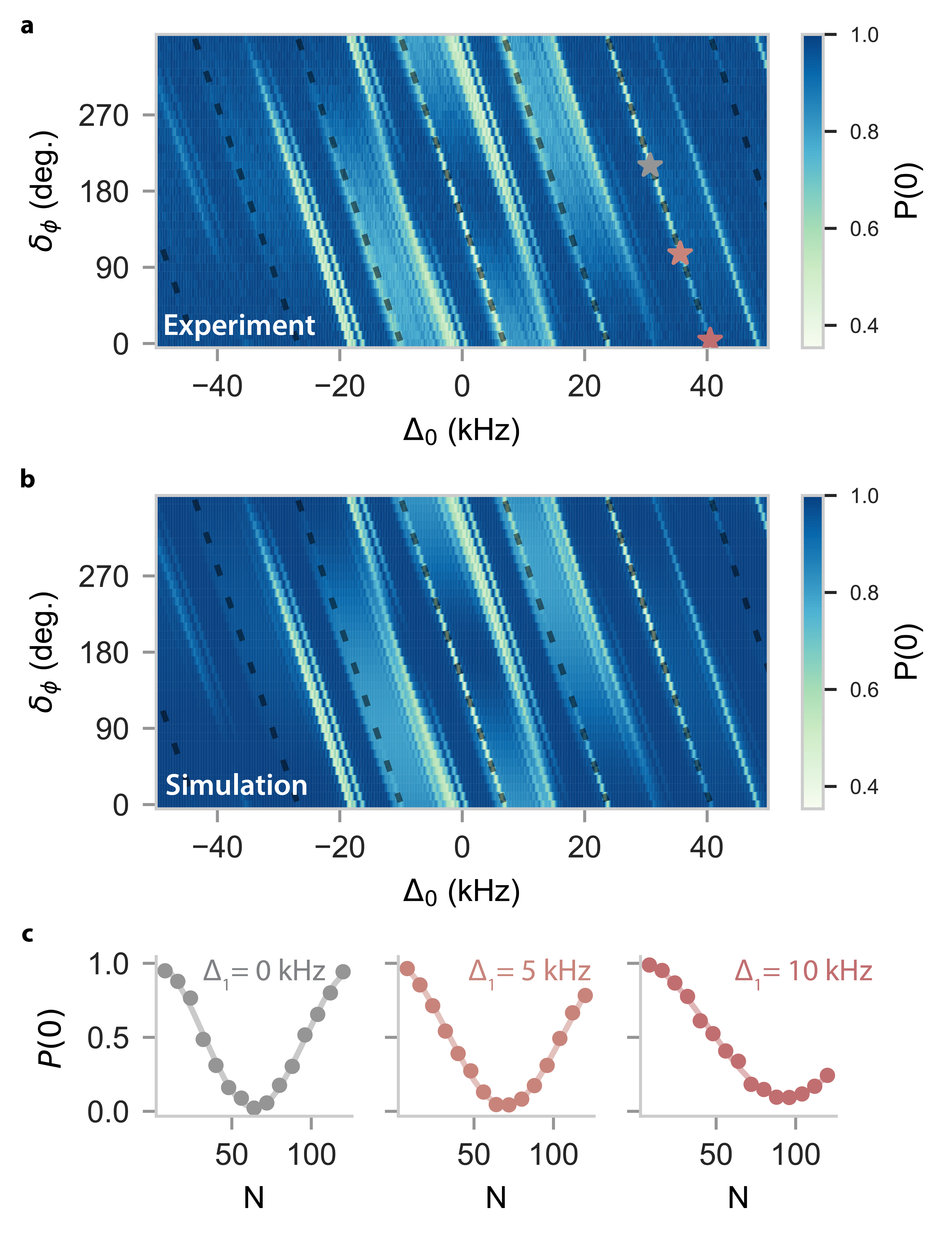
To verify equations 3 and 5 experimentally, we perform nuclear spin spectroscopy using DDRF, by varying both the RF frequency and single-pulse phase increment (Fig. 2a, similar to Fig. 1d). First the electron spin is initialized in a superposition. A drop in measured electron coherence after application of the DDRF gate indicates entanglement between the electron spin and one or more of the unpolarized nuclear spins.
We observe a number of traces that all follow the predicted resonance condition from Eq. 3. The spectrum shows isolated traces indicating interactions with single nuclear spins, and a broad band-like feature corresponding to a bath of weakly coupled spins. The measured data is well-recreated by a numerical simulation modelling 15 individual spins (labels and couplings in Table 1), together with a statistically distributed spin bath of many weakly coupled spins (Fig 2b, see Appendix C for simulation details).
Next, we show that the phase-increment condition (Eq. 3), together with the single-pulse bandwidth, enables the construction of electron-nuclear gates even if the RF driving frequency is far off resonance (). We perform such detuned gates on a single nuclear spin () and compare them to an on-resonant gate applied to the same spin (Fig. 2c). All gates achieve near-unity contrast (up to some decay due to experimental noise), though the detuned version yields a reduced gate speed as predicted by Eq. 5. We further confirm the entangling nature of detuned gates by evaluating the process matrix obtained from numerical simulations (see Appendix D).
The discussion in this section shows that nuclear-spin resonance conditions are set by both the RF frequency and the single-pulse phase increment. Furthermore, quantum gates can be constructed even with significantly detuned driving frequencies by properly updating the pulse phases. This insight expands the parameter space from which gates and sensing sequences can be constructed, yielding additional possibilities for optimisation.
IV Weak-coupling regime ()
When the bandwidth related to the RF pulses () is larger than, or on the same order as the hyperfine splitting , it is no longer valid to assume driving of only one of the nuclear spin transitions and (Fig. 3a, Eq. 2). In this commonly encountered regime, rotations for the electron state can cancel (or add to) the rotations for the electron state, reducing (or enhancing) the effective rotation.
We first consider the conditional gate (Eq. 4), for which the phase shift in inverts the RF rotation axis between subsequent pulses. In the limit of small , is strongly attenuated (Eq. 5), proportional to for on-resonance addressing (), and proportional to for the optimal driving condition discussed in the next section (see Fig. 4b). Additionally, the extrema of shift away from the transitions (Fig. 3b and Eq. 9). This explains why the spectroscopy signals of weakly coupled spins () are suppressed and appear at detuned frequencies (broad features in Fig. 2a).
This analysis reveals an inherent trade-off present in DDRF gates. While a short interpulse delay improves the electron spin’s coherence [15], it also reduces the effective Rabi frequency, thereby increasing the total gate duration required for a gate, or requiring an increase in at the cost of heating and eventually leaving the regime.
We experimentally validate Eq. 5 by driving nuclear spin at different RF frequencies, while updating the RF phases according to Eq. 3 (Fig. 3d). This amounts to tracking the nuclear resonance condition apparent in Fig. 2a. Such a measurement directly yields the spectral signature of the reduced Rabi frequency, which is in good agreement with Eq. 5.
We repeat this measurement for different numbers of pulses (), keeping the RF amplitude ( Hz at ) and the total DDRF driving time ( 1.4 ms) fixed. For higher (shorter RF pulse duration ), a decrease in signal contrast and a shift of the optimal RF frequency can be observed, as predicted by Eq. 5. We attribute the mismatch between theory and experiment for high number of pulses () to the larger relative influence of the specific shape of the RF pulse envelope used in the experiment (, Appendix A), and the frequency-dependent RF transmission of the signal chain, which are not taken into account by the model.
The DDRF gate can also be used to perform an unconditional rotation of the nuclear spin, by leaving out the phase shift from (Eq. 3) [14]. The DDRF gate unitary then becomes
| (6) |
with effective (unconditional) Rabi frequency (Fig. 3c):
| (7) |
In contrast to the conditional case, is now significantly enhanced at small . In the limit the effective Rabi frequency approaches .
The cause can again be understood by considering the effects of the individual RF pulses during the DDRF sequence. Because of the short pulse length the RF pulses cause nearly the same nuclear spin rotation regardless of the electron spin state. Compared to the conditional gate, where the extra phase shift causes the rotations to cancel, now they add up constructively, and the total rotation due to the DDRF sequence approaches , where is the total sequence length. Thus, the unconditional DDRF gate rotation speed approaches that of a single RF pulse.
We identify three approaches for mitigating the adverse effects of the reduced Rabi frequency for conditional gates. First, for a fixed gate length , the number of decoupling pulses can be traded for RF pulse length (), shrinking the pulse bandwidth to avoid driving both transitions. This comes at the cost of decreasing effectiveness of the electron decoupling, as longer interpulse delays protect less effectively against fluctuating noise sources [15]. Second, given a certain pulse length, the RF frequency can be detuned to maximise Eq. 5. Third, one could increase the physical RF amplitude to compensate for the reduction in Rabi frequency, although such a strategy poses practical challenges due to the required RF powers (and the corresponding heating of the sample), and is ultimately limited by power broadening. The next sections explore these approaches in more detail, in the context of a nuclear sensing protocol, and controlling a multi-spin register.
V Optimal sensitivity for sensing a single nuclear spin
To highlight the practical significance of the presented insights, we demonstrate how to optimise the DDRF sequence for sensing a single, weakly coupled nuclear spin (with hyperfine coupling ). For example, this nuclear spin could be a single proton or 13C spin, potentially outside of the host crystal [31]. The goal is to minimise the (single-spin) sensitivity, defined as [32](Appendix E):
| (8) |
where is the sensor decoherence function (here taken from the experimental observations of Ref. [15]), is the maximum attainable effective Rabi frequency (given and ), and is the single-experiment sensing time [32]. For simplicity, we assume unity readout contrast and zero sensor overhead (Appendix E).
The expression for in Eq. 8 conveys the minimum number of nuclear spins required that together yield a detectable signal in 1 s of integration time. Evidently, to achieve single-spin sensitivity (), the effective Rabi frequency , which sets the effective coupling to the signal, should be as large as possible, while retaining sufficient electron coherence (). The choice of presents us with an inherent trade-off between these two factors. Generally, larger (shorter -values) increase the electron coherence, but decrease (see Sec. IV). However, optimising over the large parameter space is challenging.
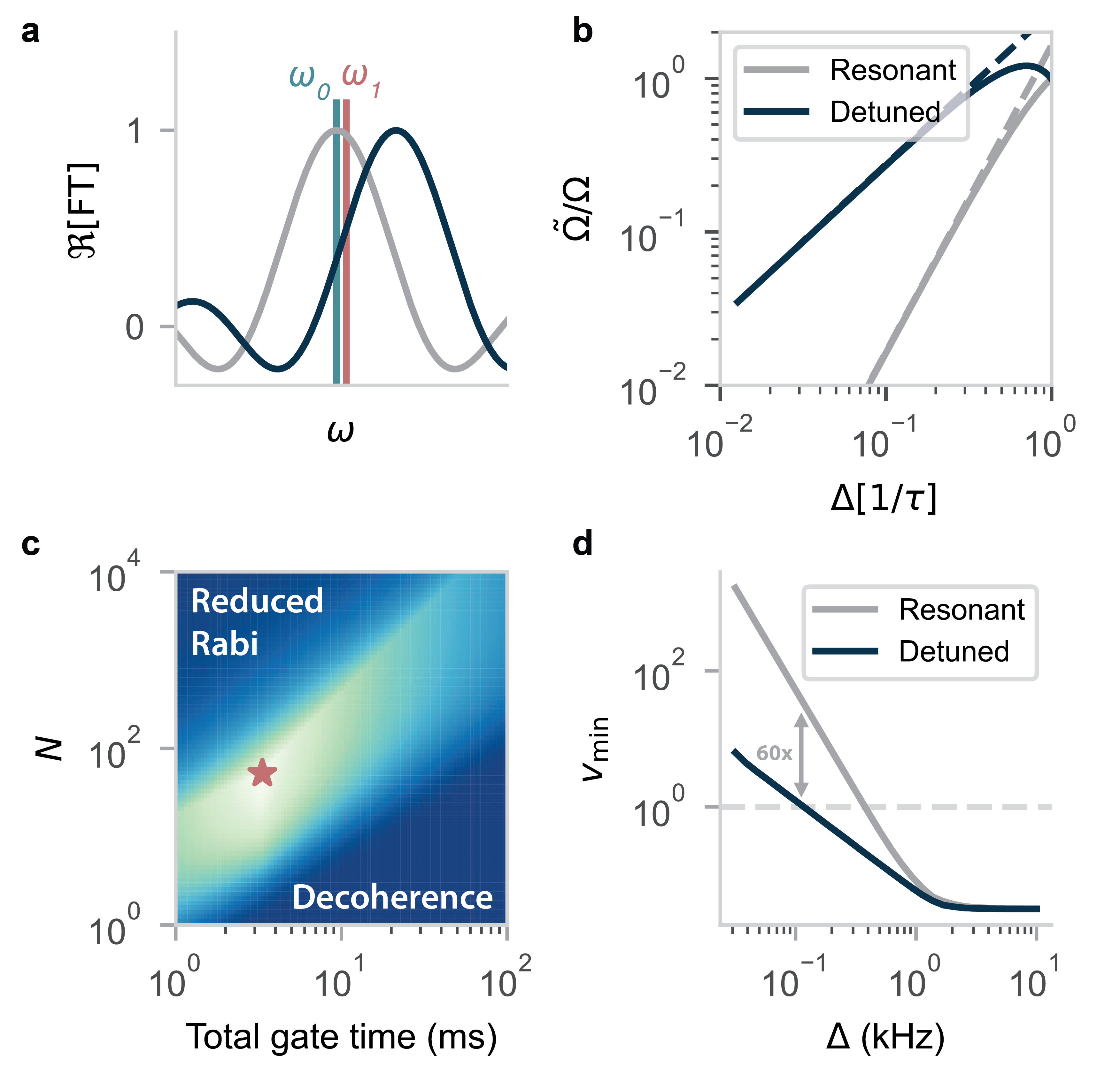
We first reduce the parameter space size by calculating the RF detuning that maximises . For , the RF driving when the electron in in the state can be neglected and the optimal effective Rabi frequency is always attained when driving on resonance (). However, when , significant enhancement is possible by detuning the RF frequency. We find that the optimum setting for is (approximately) given by (Appendix F):
| (9) |
where is the first root of the second derivative of the sinc function. Conceptually, this condition is satisfied when the detuning is such that the gradient of the RF pulse envelope is maximal in between the and transitions (Fig. 4a). While for , , using the optimum changes the scaling to (Fig. 4b). We verify that Eq. 9 maximises Eq. 5 in the small regime (Appendix F).
Next, we evaluate the optimal RF amplitude. For the situation of a very weakly coupled spin, the reduced Rabi frequency can be partially compensated for by increasing the physical RF amplitude . However, simply setting the RF amplitude to the inverse of leads to unrealistically high values when . Moreover, our model of the effective Rabi frequency strictly only holds for . Therefore, in the current analysis, we set an upper bound for the RF amplitude: . Additionally, we limit the maximum value to , as higher Rabi frequencies are typically challenging to reach without specialised RF transmitters, especially at cryogenic temperatures [33, 34].
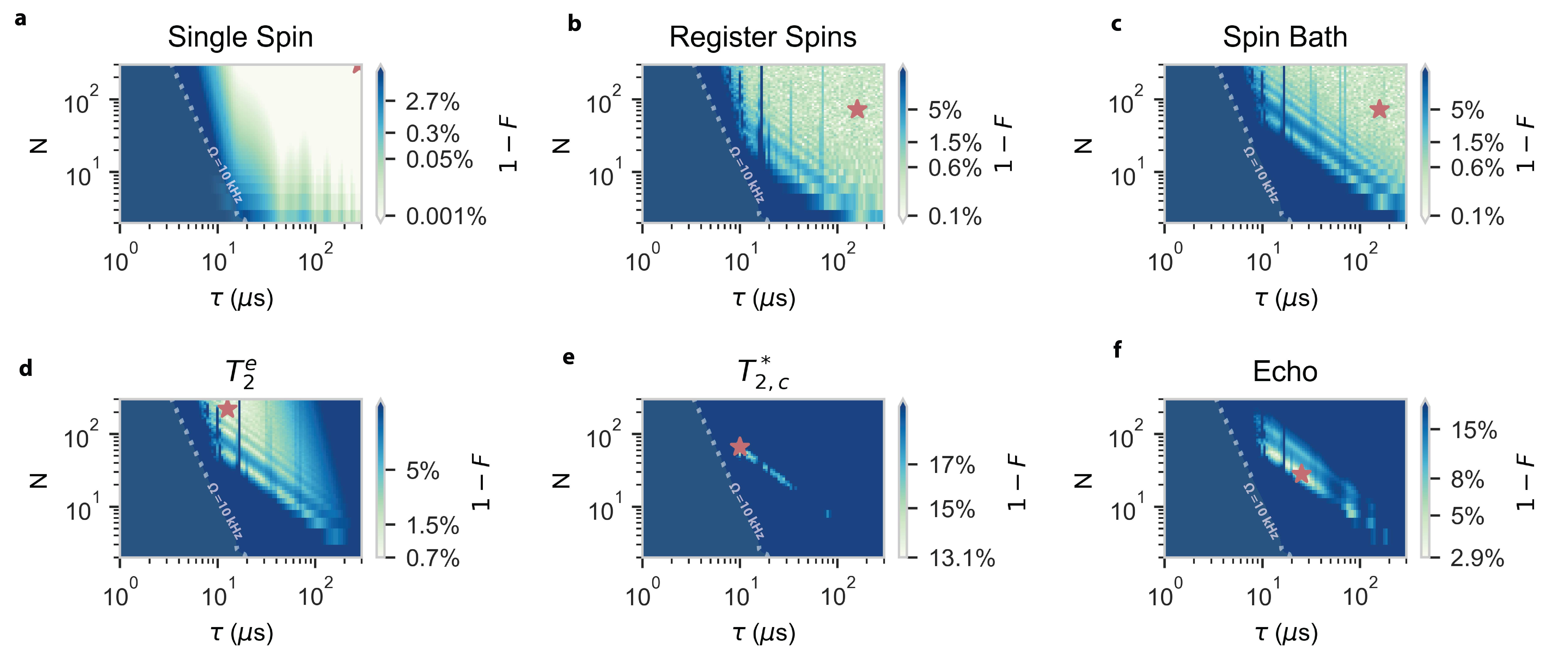
Then, to find the optimal sensing parameters, we evaluate (the inverse of) Eq. 8, sweeping the number of pulses and total sequence time , while continuously updating the RF detuning and RF amplitude to maximise (Fig. 4c and Supplementary Note 3). As expected, there exists an optimal regime that balances the expected reduction in Rabi frequency and electron decoherence (bright sliver in Fig. 4c). We compare the sensitivity of the (conventional) resonant gate with the detuned protocol by extracting the optimal value for various (Fig. 4d) and find that the latter outperforms the former for small . A divergence between the two can be observed at kHz, with the detuned protocol still achieving single-spin sensitivity at a mere Hz hyperfine coupling, a performance enhancement by a factor 60. Conversely, a statistically polarised ensemble of 100 13C spins would be detectable from a distance of nm, compared to nm for the resonant protocol (assuming the spin coherence of Ref. [15] continues to hold).
VI Quantum gate selectivity
Finally, we consider the use of the DDRF gate sequence for qubit control [21, 9, 14]. The challenge is to realise a high-fidelity (two-qubit) gate on a selected nuclear spin, while avoiding crosstalk to other spins. First, we consider the selectivity of the gates starting from the above results (Eqs. 1-5). In the next section, we simulate a realistic spin register and identify the parameter regime(s) in which high fidelity gates are possible.
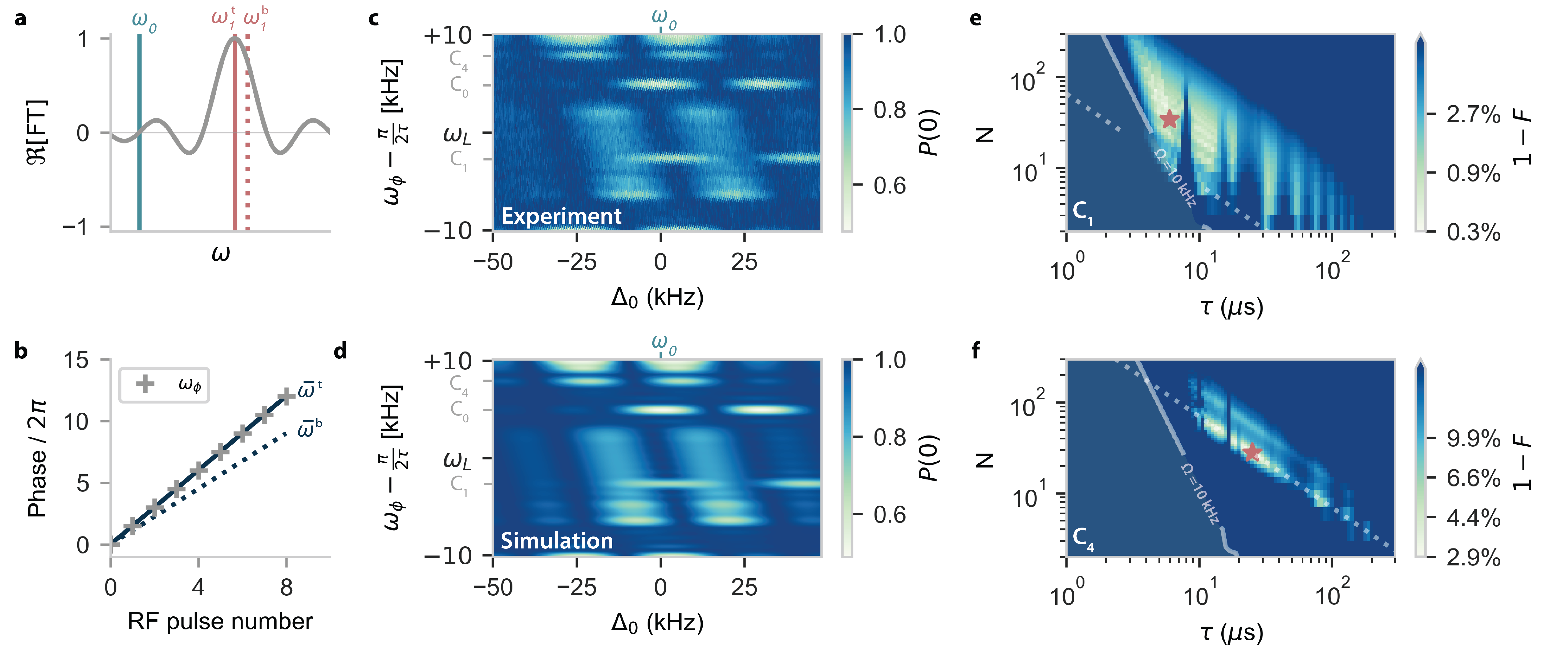
We identify two selectivity mechanisms for the DDRF gate: selective driving due to the limited bandwidth of a single RF pulse (Fig. 5a), and the constructive build-up of small rotations due to the phase- increment condition being met for a specific nuclear spin (Fig. 5b). Selective control can be achieved through either mechanism, or through a combination thereof (see e.g. Fig. 5c and d). To quantitatively study these mechanisms, we consider a target nuclear spin qubit , and a second, bystander, nuclear spin for which crosstalk is to be avoided.
For the selectivity stemming from the individual RF pulses, Eq. 5 can directly be used to yield the smallest difference in nuclear-spin transitions for which :
| (10) |
where the superscript and are used to denote the target and bystander spins, respectively. Evidently, the selectivity stemming from the RF pulses is limited by their bandwidth (). For the NV- electron spin-1 system considered here, the minimum difference between nuclear-spin hyperfine couplings required for achieving selectivity within a single RF pulse is
| (11) |
Next, to describe the selectivity due to the phase increments, it is instructive to realise that the phase increments effectively modulate the bare RF frequency (also known as ‘phase ramping’ [35]), so that we can define a phase-increment frequency:
| (12) |
We can then rewrite the phase-increment resonance condition (Eq. 3) as:
| (13) |
with . Here, selectivity arises due to the difference in the mean frequencies of the target and bystander spins, which has to be large enough for selective control.
A lower bound on the mean frequency difference can be attained by considering the Fourier-limited frequency resolution of the phase ramp (determined by its length ):
| (14) |
where the modulo stems from the periodicity in Eq. 13. Although Eq. 14 strictly speaking only constitutes an upper bound to the selectivity, it allows for a potential selectivity enhancement by a factor compared to Eq. 10. Whether such an enhancement is possible in practice depends on the the spectrum of for the electron-nuclear spin system of interest. For example, for a spin-1/2 defect spin, the left-hand side of Eq. 14 vanishes, up to second order corrections due to the perpendicular hyperfine component ([29, 30]).
For the spin-1 system considered here, an exact bound for the selectivity can be derived, under the assumption of negligible driving in the electron state (Appendix G). In particular, fixing to create a fully entangling gate, the condition for a selective gate on the target spin is given by:
| (15) |
To illustrate the selectivity mechanisms, we again perform DDRF spectroscopy (similar to Fig.2a), but instead of , we now plot the data as a function of (Fig. 5c, d). This is a useful quantity as it is independent of the RF frequency, and directly relates to a spin’s mean frequency. Spins appear at their frequency along the axis (), with their signal intensity modulated by the effective Rabi frequency (Eq. 5), which varies with (-axis). The signal from the spin bath (slanted band-like features) is pushed away from due to the form of Eq. 5 in the weak-coupling regime (section IV).
The widths of the spin response along both axes partly determine if the spin can be selectively controlled or overlaps with other spins (crosstalk), as given in equations 11 and 15. The periodicity of creates opportunities for unexpected crosstalk to occur. For example, both the and transition of nuclear spin (, Table 1), somewhat overlap with sidelobes of the spin bath, limiting the expected gate fidelity of that spin for these gate parameters. In contrast, the transitions of spin (, Table 1) is not affected by such crosstalk, due to the particular value of used here. Note that for electron spin-1/2 systems, all nuclear spins will appear at approximately (up to second order corrections due to ), so that selective control depends more on whether spins can be resolved along the -axis [29].
VII A multi-qubit nuclear-spin register
We apply the insights from the previous section to investigate the gate parameter space that allows for high-fidelity control in a multi-qubit nuclear-spin system. Considering the 15 identified spins near the NV center (Table 1), we select a register of 5 nuclear spins that are most isolated in frequency space: , , , and . For a register with nuclear spins, the ideal operation is given by:
| (16) |
where the controlled rotation acts on the electron and target spin subspace.
In addition to the unitary evolution dictated by (Eq. 2), we include three additional contributions to the infidelity (Supplementary Note 4): (i) the electron-spin dephasing time under dynamical decoupling (taken from Ref. [15]). (ii) Electron-spin dephasing due to interaction with the characterised nuclear spins outside the register and the nuclear spin bath (in a mixed state). (iii) dephasing ([14]) of the nuclear spins in the register, simulated as quasi-static magnetic field noise. As is commonly done in experimental settings, we introduce a post-gate echo pulse on the register spins to partially mitigate this dephasing [21, 14]. Additionally, we restrict the RF amplitude to a maximum value of (as in section V).
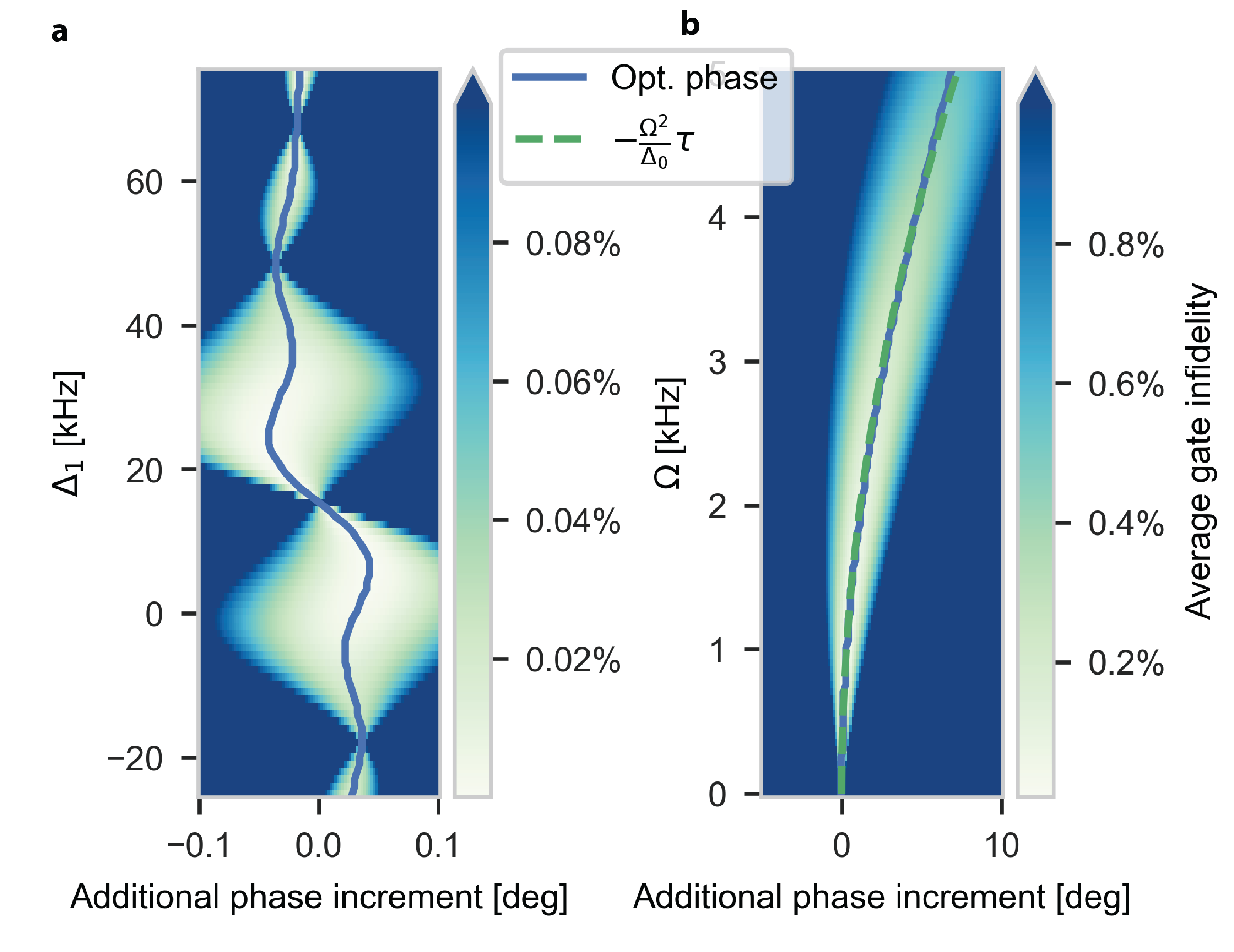
To identify optimal gate parameters, we vary the interpulse delay and the number of pulses , while ensuring the RF amplitude is set to create the desired rotation (compensating for the reduction in effective Rabi frequency using Eq. 5). We set to the target spin’s transition and calculate accordingly (Eq. 3), applying a second-order correction due to the AC-Stark shift (Appendix D).
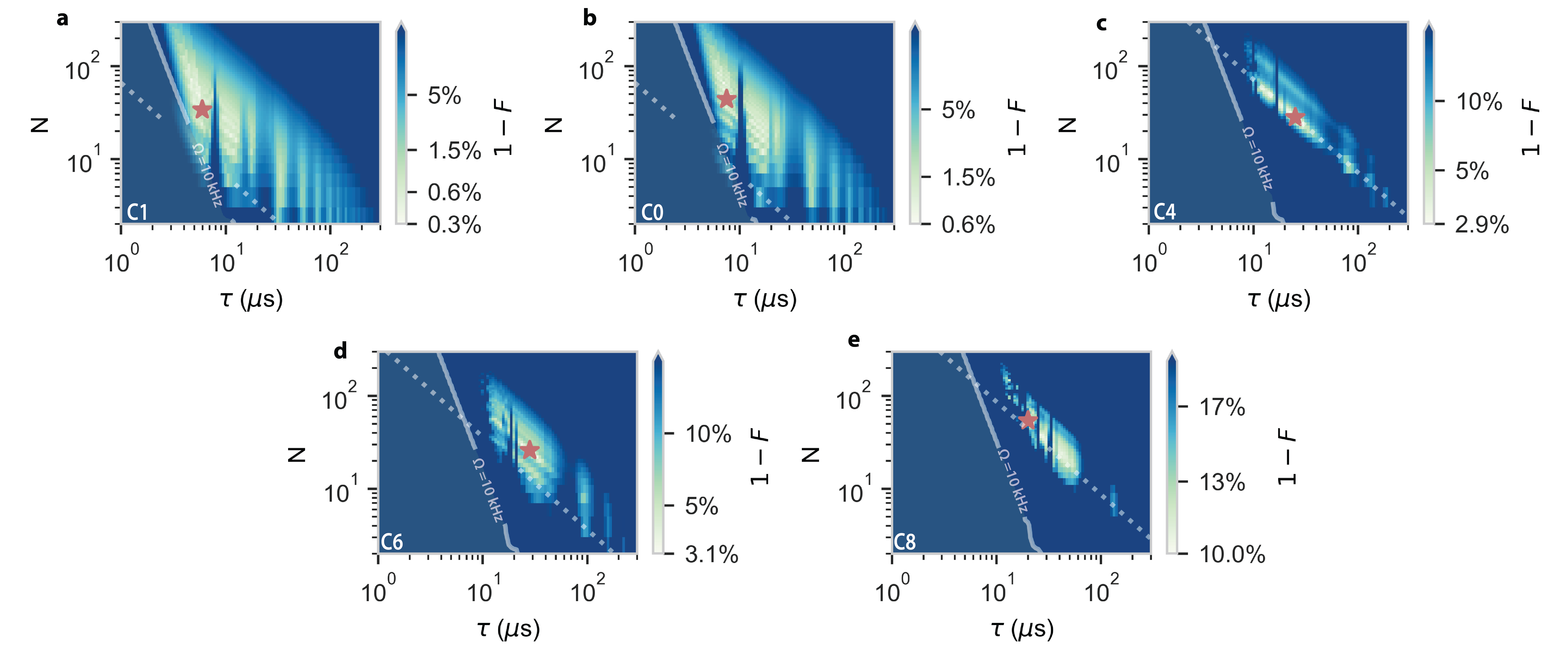
We obtain (6-qubit) average gate fidelity maps [36], such as presented in Fig. 5e and f, for target nuclear spins and , respectively (Table 1). We identify the following bounds on the available parameter space for high-quality gates. First, independent of the selected target spin, the maximum gate time is limited by nuclear- and electron-spin decoherence, the latter of which also depends on the choice of and . On the other hand, a minimum gate time is dictated by the degree of spectral crowding of the target spin, as predicted by Eq. 14. Contrary to , is spectrally close to another spin (, ), so that high-fidelity gates are only possible for higher gate times (). In particular, through the definition of the selectivity (Appendix G), equalising Eq. 15 (dotted line in Fig. 5f), ensures zero crosstalk with the nearest bystander spin ().
Furthermore, even though the reduction in effective Rabi frequency can in principle be fully compensated for, when , the assumptions underlying Eq. 5 break down (Supplementary Note 2), and our prediction for the optimal gate parameters no longer produces high-fidelity gates (top left corner of Figs. 5e and f). For spins with smaller hyperfine couplings (e.g. ), this effect is more detrimental to the maximum attainable fidelity. Finally, the remaining parameter space is interspersed with sharp drops in fidelity at -values for which crosstalk occurs with other individual spins, or with the nuclear spin bath. The combination of these effects results in maximimum 6-qubit gate fidelities of and for target spins and , respectively. See Supplementary Note 4 for the other register spins, and simulations separately demonstrating the effects of the different infidelity contributions.
Note that here we did not optimize , which could further reduce crosstalk and realize improved effective Rabi frequencies (see section V).
VIII Conclusions
In conclusion, we presented a generalised framework for electron-nuclear DDRF gates, explicitly incorporating the bandwidth of the RF pulses in the sequence. We defined a phase-increment condition so that large bandwidths can be leveraged to construct off-resonant quantum gates and sensing protocols, enhancing their flexibility and sensitivity, respectively.
We derived an analytical expression for the effective Rabi frequency under such off-resonant RF driving, which we experimentally verified. For short interpulse delays, the Rabi frequency can be strongly suppressed, setting an inherent trade-off between gate efficiency and the protection of electron spin coherence. Our proposed detuned sensing scheme partially mitigates this effect, making DDRF a promising alternative to conventional nuclear dynamical-decoupling spectroscopy in the context of nano-NMR [12, 18, 37].
Furthermore, we shed light on the selectivity mechanisms of the DDRF gate, showing that both a spin’s resonance frequency and its mean frequency under dynamical decoupling offer means of selective control in the presence of other spins. These findings have important implications for DDRF gates using spin-1/2 defect centers [29]. Finally, we presented numerical simulations that identify the optimal gate parameters for 5 nuclear spins using the NV center considered in this work. We uncovered the key requirements for high-fidelity gates, guiding the design of DDRF gates in multi-spin registers.
Acknowledgements
We thank H. P. Bartling and C. E. Bradley for useful discussions. We gratefully acknowledge support from the joint research program “Modular quantum computers” by Fujitsu Limited and Delft University of Technology, co-funded by the Netherlands Enterprise Agency under project number PPS2007. We acknowledge financial support from the Quantum Internet Alliance through the Horizon Europe program (grant agreement No. 101080128). This project has received funding from the European Research Council (ERC) under the European Union’s Horizon 2020 research and innovation programme (grant agreement No. 852410). This work was supported by the Dutch National Growth Fund (NGF), as part of the Quantum Delta NL programme. This work is part of the research programme NWA-ORC with project number NWA.1160.18.208, which is (partly) financed by the Dutch Research Council (NWO). This project has received funding from the European Union’s Horizon Europe research and innovation program under grant agreement No 101135699.
APPENDIX A EXPERIMENTAL METHODS
All experiments are conducted on a naturally occurring NV center using a custom-built cryogenic confocal microscopy setup (4K, Montana Cryostation). The diamond sample, which has a natural abundance of 1.1% 13C, was homoepitaxially grown via chemical vapor deposition (Element Six) and cleaved along the crystal direction.
A solid immersion lens (SIL) is milled around the NV center to improve photon collection efficiency[42]. A gold stripline is deposited near the edge of the SIL for the application of microwave (MW) and radio-frequency (RF) pulses. Typical nuclear Rabi frequencies can reach up to , above which sample heating starts to affect the NV readout. MW and RF signals are generated by a ZI HDAWG Arbitrary Waveform Generator, in combination with a MW mixer and separate RF and MW amplifiers. An external magnetic field of is applied along the NV-symmetry axis, using a permanent neodymium magnet mounted to the back of the cryostat cold finger. An external permanent magnet is used for fine alignment of the magnetic field, resulting in negligibly small perpendicular magnetic field components.
The NV spin state is initialized via spin-pumping and read out in a single shot through spin-selective resonant excitation, with fidelities () for the () state, respectively, resulting in an average fidelity of . Reported data is corrected for these numbers to obtain a best estimate of the electronic spin state. We drive the electronic spin transition at 2.425 GHz with Hermite-shaped pulses.
In this work, XY-8 type sequences are used for dynamical decoupling during the DDRF gate, to minimize the effects of pulse errors[15]. The length of RF pulses in the DDRF sequences in this work are set to an integer number of periods of the RF radiation, to prevent the NV electron spin from picking up extra phase. Each RF pulse has a roll-on and roll-off to prevent signal ringing in the RF signal chain, with a roll-duration of two RF periods. Due to this pulse shaping, the two RF pulses of length in the DDRF sequence create a smaller combined rotation than the RF pulses of length . To correct for this, the amplitude of the single- pulses is multiplied by the ratio of the integrals of the pulse and the two single- pulses.
APPENDIX B NV HAMILTONIAN
While in general the NV center is described by a spin-1 electron coupled to a spin-1 nitrogen spin, with additional couplings to spin-1/2 spins, the approach in this work is limited to the subspace of the electron spin, and the interaction with the spin-1 nitrogen spin is neglected. The nitrogen spin ideally is initialized in the state, however the decoupling sequence also effectively disables the interaction between electron and nitrogen spin. Considering one spin, the Hamiltonian of the system is, in the interaction picture and after the rotating wave approximation, given by:
| (17) |
where and are the parallel and perpendicular components of the NV-nuclear hyperfine tensor, , and are the electron and nuclear (pseudo) spin-1/2 operators, is the physical RF amplitude, is the RF frequency, and is some phase offset of the RF field. Note that, in general, the axis of and the axis along which the RF-radiation is applied are not the same. In the present work, for simplicity, the effect of is neglected [14], further motivated by the high magnetic field (189.1 mT) at which experiments were performed. At such high fields, the tilt of the nuclear quantisation axis is small ( for ). We do take into account the changed nuclear precession frequency due to , given by: . In the rotating frame at the RF frequency (and again making the rotating wave approximation) Eq. 17 simplifies to:
| (18) |
APPENDIX C SIMULATION OF DDRF SPECTROSCOPY
Spectroscopy experiments (Figs. 2b, 5d) have been simulated assuming the presence of 15 individual nuclear spins (Table 1) and a bath of weakly coupled spins.
For an individual nuclear spins , the unitary operation of an DDRF unit-cell was calculated starting from (Eq. 2). For starting electron state (), the rotation axis () and angle of the nuclear spin rotation was determined. If the electron spin starts in the state, the expectation value after a DDRF gate with pulses is given by
| (19) |
The total signal from the individual spins is given by the product of the expectation values:
| (20) |
For the nuclear spin bath, a mean density of parallel hyperfine shifts is used [7]
| (21) |
where , and is the density of in natural abundance diamond, where is the relative abundance of atoms in the environment (), and is the density of C atoms in diamond.
Instead of calculating the bath signal for a random sample of individual spins[15], we calculate the signal for a sufficient number of bins (300 in this work) of of width . The expected number of spins in such a bin is given by . The spectroscopy signals for each bin are calculated with Eq. 19 and combined to yield the total signal of the spin bath:
| (22) |
where defines the maximum coupling strength of spins that are still considered part of the spin bath, in this work kHz. Note that this approach breaks down when the signal due to a single spin with becomes large.
The total signal is given by the product of the signals of individual spins and the spin bath.
The Rabi frequency was determined from the waveform amplitude of the RF pulses and an experimentally determined conversion factor from waveform amplitude to . The pulse length is adjusted by half the length of the pulse roll-on time (Appendix A) to approximately account for the smaller effective pulse amplitude, and the dead-time around the MW pulses is subtracted. The RF Hamiltonian is applied for a duration of , and during the dead-time we set . The simulation could be made more accurate by considering a time-dependent , matching the pulse shape, at the cost of computation time.
From the spectroscopy signal, we qualitatively identify 15 individual nuclear spins that can be distinguished from the spin bath (listed in Table 1).
| Index | (Hz) | Index | (Hz) | Index | (Hz) |
|---|---|---|---|---|---|
| -30693 | -12570 | -9500 | |||
| -45870 | 15744 | -9000 | |||
| 20000 | -10020 | -13060 | |||
| 19900 | -11160 | -6193 | |||
| 18500 | -7660 | -7200 |
APPENDIX D THEORETICAL FIDELITY OF DETUNED GATES
We present a closer study of the theoretically achievable fidelity of DDRF gates on a single nuclear spin, neglecting . We consider the spin and gate parameters from Fig. 2c: kHz, us, Hz. We numerically calculate the DDRF gate unitary using (Eq. 2) and compare it to the ideal unitary
| (23) |
To compare and , we decompose into its rotation angle , and rotation axes and , for each starting electron spin state (See more detail in Supplementary Note 1). We then calculate
| (24) |
and compare that to (Fig. D.1). This assumes that the rotation angle of the gate can be tuned to be , which could experimentally be achieved with a calibration sequence. Tuning the rotation angle with has no effect on , and fine tuning with would only slightly affect .
First we consider resonant and off-resonant DDRF gates (Fig. D.1,a). We find that high gate fidelities () are achievable for a wide range of detunings. To maximise gate fidelity, it is necessary to adjust the single-pulse phase increment slightly from the previously derived resonance condition (Eq. 3).
Increasing the Rabi frequency reveals why the optimal changes (Fig. D.1b). When driving on resonance (), the optimal phase increment is shifted by
| (25) |
We attribute this effect to the AC-Stark shift[35]. The presence of RF radiation at the frequency causes the frequency of the nuclear spin to shift, resulting in a different amount of phase being picked up by the spin while the electron is in the state. For other RF frequencies a combined effect of shifting both nuclear spin resonance frequencies occurs.
APPENDIX E EXPRESSION FOR THE SENSITIVITY
We define the single spin sensitivity according to Ref. [32]:
| (26) |
where is the single experiment sensing time, is the readout time, is a readout efficiency parameter, is the signal transduction parameter and is the coherence function of the sensor spin. For simplicity, We assume an ideal, instantaneous readout (). For the system under study here, this assumption is reasonable as the (single-shot) readout fidelity is and the readout time ( \unit\micro) is significantly shorter than the typical sensing time ( \unit\milli) [14]. In our case, is equal to the (effective) Rabi frequency and has units , as a single nuclear spin induces phase on the sensor at this rate. Eq. 26 then reduces to:
| (27) |
which is equal to Eq. 8 in the main text.
APPENDIX F OPTIMAL RF DETUNING
The optimal RF detuning condition for a specific and , is found by choosing (and corresponding ) so that Eq. 5 is maximised. As Eq. 5 and its derivatives are transcendental, it is not trivial to find these maxima. Therefore, we look for an approximate solution, by considering the function’s behaviour in the limit of long and short .
In the limit of long (defined as ), the optimal detuning is (trivially) . In this limit, the two sinc functions in Eq. 5 are completely separated and the global maximum is simply the maximum of the sinc function centered around (Fig. F.1a).
However, for short , the spectral width of the sinc functions increases, so that they interfere destructively, which pushes the optimal detuning condition outwards (Fig. F.1a). In the short limit (), we can conceptually see that maximum will be attained when the difference in driving between the and transitions is largest, as this maximises the conditional character of the gate. For the square RF pulses considered in this work, this condition is satisfied when the sinc pulse envelope has maximum gradient at (schematically illustrated in Fig 4a). By evaluating the second derivative of the sinc function, we find that the (maximum gradient) inflexion point is located at a distance away from the peak center, with the first root of the second derivative of the sinc function. Requiring this point to be positioned precisely in between the two transitions (i.e. away from ), we arrive at the condition:
| (30) |
It is not a priori obvious that these two limiting cases perform well in describing the optimal condition in the intermediate regime (). To evaluate the validity of the limiting cases, and to investigate their performance in the intermediate regime, we compute Eq. 5 for a range of -values (Fig. F.1a) and extract numerically its maximum value (Fig. F.1b, solid blue line). We compare this numerical value to a composite function, generated by joining the limiting descriptions at condition :
| (31) |
which is equal to Eq. 9 in the main text. We find good agreement between the numerical maximum, and the effective Rabi frequency obtained by inserting Eq. 31 in Eq. 5, which yields:
| (32) |
APPENDIX G BOUND FOR GATE SELECTIVITY
We present a brief mathematical justification for the DDRF gate selectivity that accumulates over the duration of the gate (14). Starting from the Hamiltonian describing RF driving of the nuclear spin if the electron is in the state:
| (33) |
a compact expression for the electron spin’s spectroscopy response can be found when the phase increment (Supplementary Note 1):
| (34) |
Note that this is the optimal phase increment when (Eq. 3). For , and for being the electron state (giving all spins the same ), the above equation predicts the electron spin’s response to a bystander spin, which diminishes due to the mismatch between and the bystander spin’s actual evolution. The minimum detuning between the bystander spin and the target spin which causes no crosstalk is given by the first zero of the electron spin’s response. Considering the case of an entangling gate between the electron and target spin (), there is no crosstalk if
| (35) |
Translating this to a difference in mean frequency results in
| (36) | ||||
| (37) |
Furthermore, the selectivity can be argued from the lorentzian factor in Eq. 34. Under the entangling gate condition , this lorentzian has a full-width at half-maximum of .
References
- Lovchinsky et al. [2016] I. Lovchinsky, A. O. Sushkov, E. Urbach, N. P. de Leon, S. Choi, K. De Greve, R. Evans, R. Gertner, E. Bersin, C. Muller, L. McGuinness, F. Jelezko, R. L. Walsworth, H. Park, and M. D. Lukin, Nuclear magnetic resonance detection and spectroscopy of single proteins using quantum logic, Science 351, 836 (2016).
- Pompili et al. [2021] M. Pompili, S. L. N. Hermans, S. Baier, H. K. C. Beukers, P. C. Humphreys, R. N. Schouten, R. F. L. Vermeulen, M. Tiggelman, L. dos Santos Martins, B. Dirkse, S. Wehner, and R. Hanson, Realization of a multinode quantum network of remote solid-state qubits, Science 372, 259 (2021).
- Abobeih et al. [2019] M. H. Abobeih, J. Randall, C. E. Bradley, H. P. Bartling, M. A. Bakker, M. J. Degen, M. Markham, D. J. Twitchen, and T. H. Taminiau, Atomic-scale imaging of a 27-nuclear-spin cluster using a quantum sensor, Nature 576, 411 (2019).
- Randall et al. [2021] J. Randall, C. E. Bradley, F. V. van der Gronden, A. Galicia, M. H. Abobeih, M. Markham, D. J. Twitchen, F. Machado, N. Y. Yao, and T. H. Taminiau, Many-body–localized discrete time crystal with a programmable spin-based quantum simulator, Science 374, 1474 (2021).
- Cujia et al. [2022] K. S. Cujia, K. Herb, J. Zopes, J. M. Abendroth, and C. L. Degen, Parallel detection and spatial mapping of large nuclear spin clusters, Nat Commun 13, 1260 (2022).
- Budakian et al. [2023] R. Budakian, A. Finkler, A. Eichler, M. Poggio, C. L. Degen, S. Tabatabaei, I. Lee, P. C. Hammel, E. S. Polzik, T. H. Taminiau, R. L. Walsworth, P. London, A. B. Jayich, A. Ajoy, A. Pillai, J. Wrachtrup, F. Jelezko, Y. Bae, A. J. Heinrich, C. R. Ast, P. Bertet, P. Cappellaro, C. Bonato, Y. Altmann, and E. Gauger, Roadmap on Nanoscale Magnetic Resonance Imaging (2023), arXiv:2312.08841 [cond-mat, physics:physics, physics:quant-ph] .
- Van De Stolpe et al. [2024] G. L. Van De Stolpe, D. P. Kwiatkowski, C. E. Bradley, J. Randall, M. H. Abobeih, S. A. Breitweiser, L. C. Bassett, M. Markham, D. J. Twitchen, and T. H. Taminiau, Mapping a 50-spin-qubit network through correlated sensing, Nat Commun 15, 2006 (2024).
- Xie et al. [2023] T. Xie, Z. Zhao, S. Xu, X. Kong, Z. Yang, M. Wang, Y. Wang, F. Shi, and J. Du, 99.92%-Fidelity cnot Gates in Solids by Noise Filtering, Phys. Rev. Lett. 130, 030601 (2023).
- Bartling et al. [2024] H. P. Bartling, J. Yun, K. N. Schymik, M. van Riggelen, L. A. Enthoven, H. B. van Ommen, M. Babaie, F. Sebastiano, M. Markham, D. J. Twitchen, and T. H. Taminiau, Universal high-fidelity quantum gates for spin-qubits in diamond (2024), arXiv:2403.10633 [cond-mat, physics:quant-ph] .
- Humphreys et al. [2018] P. C. Humphreys, N. Kalb, J. P. J. Morits, R. N. Schouten, R. F. L. Vermeulen, D. J. Twitchen, M. Markham, and R. Hanson, Deterministic delivery of remote entanglement on a quantum network, Nature 558, 268 (2018).
- Hermans et al. [2022] S. L. N. Hermans, M. Pompili, H. K. C. Beukers, S. Baier, J. Borregaard, and R. Hanson, Qubit teleportation between non-neighbouring nodes in a quantum network, Nature 605, 663 (2022).
- Taminiau et al. [2012] T. H. Taminiau, J. J. T. Wagenaar, T. van der Sar, F. Jelezko, V. V. Dobrovitski, and R. Hanson, Detection and Control of Individual Nuclear Spins Using a Weakly Coupled Electron Spin, Phys. Rev. Lett. 109, 137602 (2012).
- van der Sar et al. [2012] T. van der Sar, Z. H. Wang, M. S. Blok, H. Bernien, T. H. Taminiau, D. M. Toyli, D. A. Lidar, D. D. Awschalom, R. Hanson, and V. V. Dobrovitski, Decoherence-protected quantum gates for a hybrid solid-state spin register, Nature 484, 82 (2012).
- Bradley et al. [2019] C. E. Bradley, J. Randall, M. H. Abobeih, R. C. Berrevoets, M. J. Degen, M. A. Bakker, M. Markham, D. J. Twitchen, and T. H. Taminiau, A Ten-Qubit Solid-State Spin Register with Quantum Memory up to One Minute, Phys. Rev. X 9, 031045 (2019).
- Abobeih et al. [2018] M. H. Abobeih, J. Cramer, M. A. Bakker, N. Kalb, M. Markham, D. J. Twitchen, and T. H. Taminiau, One-second coherence for a single electron spin coupled to a multi-qubit nuclear-spin environment, Nat Commun 9, 2552 (2018).
- Bartling et al. [2022] H. P. Bartling, M. H. Abobeih, B. Pingault, M. J. Degen, S. J. H. Loenen, C. E. Bradley, J. Randall, M. Markham, D. J. Twitchen, and T. H. Taminiau, Entanglement of Spin-Pair Qubits with Intrinsic Dephasing Times Exceeding a Minute, Phys. Rev. X 12, 011048 (2022).
- Schwartz et al. [2018] I. Schwartz, J. Scheuer, B. Tratzmiller, S. Müller, Q. Chen, I. Dhand, Z.-Y. Wang, C. Müller, B. Naydenov, F. Jelezko, and M. B. Plenio, Robust optical polarization of nuclear spin baths using Hamiltonian engineering of nitrogen-vacancy center quantum dynamics, Sci. Adv. 4, eaat8978 (2018).
- Staudacher et al. [2013] T. Staudacher, F. Shi, S. Pezzagna, J. Meijer, J. Du, C. A. Meriles, F. Reinhard, and J. Wrachtrup, Nuclear Magnetic Resonance Spectroscopy on a (5-Nanometer) 3 Sample Volume, Science 339, 561 (2013).
- Cujia et al. [2019] K. S. Cujia, J. M. Boss, K. Herb, J. Zopes, and C. L. Degen, Tracking the precession of single nuclear spins by weak measurements, Nature 571, 230 (2019).
- Taminiau et al. [2014] T. H. Taminiau, J. Cramer, T. van der Sar, V. V. Dobrovitski, and R. Hanson, Universal control and error correction in multi-qubit spin registers in diamond, Nature Nanotech 9, 171 (2014).
- Abobeih et al. [2022] M. H. Abobeih, Y. Wang, J. Randall, S. J. H. Loenen, C. E. Bradley, M. Markham, D. J. Twitchen, B. M. Terhal, and T. H. Taminiau, Fault-tolerant operation of a logical qubit in a diamond quantum processor, Nature 606, 884 (2022).
- Parthasarathy et al. [2023] S. K. Parthasarathy, B. Kallinger, F. Kaiser, P. Berwian, D. B. Dasari, J. Friedrich, and R. Nagy, Scalable Quantum Memory Nodes Using Nuclear Spins in Silicon Carbide, Phys. Rev. Applied 19, 034026 (2023).
- Nagy et al. [2019] R. Nagy, M. Niethammer, M. Widmann, Y.-C. Chen, P. Udvarhelyi, C. Bonato, J. U. Hassan, R. Karhu, I. G. Ivanov, N. T. Son, J. R. Maze, T. Ohshima, Ö. O. Soykal, Á. Gali, S.-Y. Lee, F. Kaiser, and J. Wrachtrup, High-fidelity spin and optical control of single silicon-vacancy centres in silicon carbide, Nature Communications 10, 1954 (2019).
- Uysal et al. [2023] M. T. Uysal, M. Raha, S. Chen, C. M. Phenicie, S. Ourari, M. Wang, C. G. Van De Walle, V. V. Dobrovitski, and J. D. Thompson, Coherent Control of a Nuclear Spin via Interactions with a Rare-Earth Ion in the Solid State, PRX Quantum 4, 010323 (2023).
- Higginbottom et al. [2022] D. B. Higginbottom, A. T. K. Kurkjian, C. Chartrand, M. Kazemi, N. A. Brunelle, E. R. MacQuarrie, J. R. Klein, N. R. Lee-Hone, J. Stacho, M. Ruether, C. Bowness, L. Bergeron, A. DeAbreu, S. R. Harrigan, J. Kanaganayagam, D. W. Marsden, T. S. Richards, L. A. Stott, S. Roorda, K. J. Morse, M. L. W. Thewalt, and S. Simmons, Optical observation of single spins in silicon, Nature 607, 266 (2022).
- Debroux et al. [2021] R. Debroux, C. P. Michaels, C. M. Purser, N. Wan, M. E. Trusheim, J. Arjona Martínez, R. A. Parker, A. M. Stramma, K. C. Chen, L. de Santis, E. M. Alexeev, A. C. Ferrari, D. Englund, D. A. Gangloff, and M. Atatüre, Quantum Control of the Tin-Vacancy Spin Qubit in Diamond, Phys. Rev. X 11, 041041 (2021).
- Sipahigil et al. [2016] A. Sipahigil, R. E. Evans, D. D. Sukachev, M. J. Burek, J. Borregaard, M. K. Bhaskar, C. T. Nguyen, J. L. Pacheco, H. A. Atikian, C. Meuwly, R. M. Camacho, F. Jelezko, E. Bielejec, H. Park, and M. Lon, An integrated diamond nanophotonics platform for quantum-optical networks, Science , 5 (2016).
- Hannes et al. [2024] W.-R. Hannes, R. Finsterhoelzl, and G. Burkard, Fidelity of photon-mediated entanglement between remote nuclear-spin multi-qubit registers (2024), arXiv:2401.06705 [cond-mat, physics:quant-ph] .
- Beukers et al. [2024] H. K. C. Beukers, C. Waas, M. Pasini, H. B. van Ommen, N. Codreanu, J. M. Brevoord, T. Turan, M. Iuliano, Z. Ademi, T. H. Taminiau, and R. Hanson, Quantum control of solid-state nuclear spin qubits using an electronic spin-1/2 (2024), arXiv:2409.08977 [physics:quant-ph] .
- Zahedian et al. [2024] M. Zahedian, V. Vorobyov, and J. Wrachtrup, Blueprint for efficient nuclear spin characterization with color centers, Phys. Rev. B 109, 214111 (2024).
- Schwartz et al. [2019] I. Schwartz, J. Rosskopf, S. Schmitt, B. Tratzmiller, Q. Chen, L. P. McGuinness, F. Jelezko, and M. B. Plenio, Blueprint for nanoscale NMR, Sci Rep 9, 6938 (2019).
- Degen et al. [2017] C. L. Degen, F. Reinhard, and P. Cappellaro, Quantum sensing, Rev. Mod. Phys. 89, 035002 (2017).
- Herb et al. [2020] K. Herb, J. Zopes, K. S. Cujia, and C. L. Degen, Broadband radio-frequency transmitter for fast nuclear spin control, Review of Scientific Instruments 91, 113106 (2020).
- Yudilevich et al. [2023] D. Yudilevich, A. Salhov, I. Schaefer, K. Herb, A. Retzker, and A. Finkler, Coherent manipulation of nuclear spins in the strong driving regime, New J. Phys. 25, 113042 (2023).
- Vandersypen and Chuang [2005] L. M. K. Vandersypen and I. L. Chuang, NMR techniques for quantum control and computation, Rev. Mod. Phys. 76, 1037 (2005).
- Nielsen [2002] M. A. Nielsen, A simple formula for the average gate fidelity of a quantum dynamical operation, Physics Letters A 303, 249 (2002).
- Mamin et al. [2013] H. J. Mamin, M. Kim, M. H. Sherwood, C. T. Rettner, K. Ohno, D. D. Awschalom, and D. Rugar, Nanoscale Nuclear Magnetic Resonance with a Nitrogen-Vacancy Spin Sensor, Science 339, 557 (2013).
- Hensen et al. [2020] B. Hensen, W. Wei Huang, C.-H. Yang, K. Wai Chan, J. Yoneda, T. Tanttu, F. E. Hudson, A. Laucht, K. M. Itoh, T. D. Ladd, A. Morello, and A. S. Dzurak, A silicon quantum-dot-coupled nuclear spin qubit, Nat. Nanotechnol. 15, 13 (2020).
- Ruskuc et al. [2022] A. Ruskuc, C.-J. Wu, J. Rochman, J. Choi, and A. Faraon, Nuclear spin-wave quantum register for a solid-state qubit, Nature 602, 408 (2022).
- Bradley et al. [2022] C. E. Bradley, S. W. De Bone, P. F. W. Möller, S. Baier, M. J. Degen, S. J. H. Loenen, H. P. Bartling, M. Markham, D. J. Twitchen, R. Hanson, D. Elkouss, and T. H. Taminiau, Robust quantum-network memory based on spin qubits in isotopically engineered diamond, npj Quantum Inf 8, 122 (2022).
- de Bone et al. [2024] S. de Bone, P. Möller, C. E. Bradley, T. H. Taminiau, and D. Elkouss, Thresholds for the distributed surface code in the presence of memory decoherence (2024), arXiv:2401.10770 [quant-ph] .
- Robledo et al. [2011] L. Robledo, L. Childress, H. Bernien, B. Hensen, P. F. A. Alkemade, and R. Hanson, High-fidelity projective read-out of a solid-state spin quantum register, Nature 477, 574 (2011).
- Munuera-Javaloy et al. [2023] C. Munuera-Javaloy, A. Tobalina, and J. Casanova, High-Resolution NMR Spectroscopy at Large Fields with Nitrogen Vacancy Centers, Phys. Rev. Lett. 130, 133603 (2023).
Supplementary Information for
“Improved Electron-Nuclear Quantum Gates for Spin Sensing and Control”
Supplementary Note 1 Analytic Description of DDRF Gates
volution during a DDRF gate, when RF driving is neglected when the electron is in . Although this approximation is only valid in the regime where , it provides much insight in the spin dynamics for the general case.
The electron-nuclear Hamiltonian, only considering driving the electron state, in the rotating frame of the RF radiation, is given by:
| (S1.1) |
The following derivation shows similarities to the derivation used to analyse resonant DD control of nuclear spins [12]. In this approximation of driving during only one electron state, there are two differences between DD and DDRF: the Rabi frequency takes the role of in resonant DD, and the phase of the RF driving can be changed between pulses, while for DD always acts along the same axis in the lab frame.
The unitary operator that describes the action of a single (N=2) DDRF block is given by
| (S1.2) |
where are the phase jumps of the RF radiation in between pulses, represented as z-rotations of the nuclear-spin qubit’s rotating frame, and are rotations of angle around the x-axis of the electron spin, representing the decoupling pulses.
Due to the block-diagonal nature of the driving Hamiltonian we can define , with the unitary operators describing the nuclear spin evolution if the electron spin is in state . A DDRF gate with decoupling pulses can then be written as:
| (S1.3) | ||||
| (S1.4) |
which is a similar form as obtained for DD in ref. [12]. Any DDRF gate with more pulses can be found from . The operator () is the unitary evolution of the nuclear spin during one DDRF gate unit cell with the electron spin initially in ().
Again analogous to Ref. [12], and can be interpreted as rotations of the nuclear spin under an angle , and around axes and : , with . The rotation angle and the inner product of the rotation axes are given by
| (S1.5) | ||||
| (S1.6) |
where . For larger , the solution is given by the same rotation axes, but by a rotation angle .
The key difference with the analytical result for DD gates is that the resonance condition for an entangling gate can be fulfilled by setting appropriately, whereas for DD only the decoupling time can be used. Tracking the nuclear spin evolution by setting , we find:
| (S1.7) | ||||
| (S1.8) |
A fully entangling gate (e.g. ) can be performed when .
Due to the () nature of the interaction, it is useful to consider an experiment where the electron is prepared in and a DDRF sequence is applied. With the nuclear spin in a mixed state, the probability for the electron spin to remain in the state is given by , with [12]:
| (S1.9) |
which, under the resonance condition , is equal to:
| (S1.10) |
Alternatively, can be set to optimally drive a target spin for , tracking its phase evolution during the gate. The solution is (same as Eq. 3, see Supplementary Note 2 for a derivation). In this case, Eq. S1.5 can be approximated in the limit of small rotations per RF pulse () to yield:
| (S1.11) |
so that each DDRF block induces a rotation of the nuclear spin by:
| (S1.12) |
This matches the effective Rabi frequency in the main text(Eq. 5), in the limit considered here where the driving in the state is neglected () and demonstrates the RF pulse bandwidth due to . The more general case is derived in the next section (Supplementary Note 2).
Supplementary Note 2 Effective Rabi Frequency Derivation
As additional justification to the equation for (Eq. 5), next to the experimental data in the main text, we present a derivation that shows that the DDRF gate can be approximated by a rotation with a reduced Rabi frequency.
The matrix exponentials and , as defined in section Supplementary Note 1, can be explicitly calculated:
| (S2.13) | |||
| (S2.14) |
where and are the Pauli spin matrices. This form allows an efficient and accurate numerical calculation of the unitary operator of the DDRF gate (as only multiplication of matrices is required), which was used to calculate the individual spin signals in Fig. 2b, Fig 5d (Appendix C).
Directly calculating or results in an analytically complex expression that is not easily simplified. Progress can be made by considering the limit . This is justified as DDRF is designed to target weakly-coupled nuclear spins () for which decoupling of the electron spin is needed, breaking up the rotation of the nuclear spin into small amounts.
To first order in , (Eq. S1.3) can be approximated by
Thus the action of the DDRF gate on the nuclear spin can be approximated by a z-rotation, and an x-rotation by an angle that scales linearly with , as would be expected. The derivation also shows the resonance conditions. Setting results in:
| (S2.15) | ||||
| (S2.16) |
which describes (to first order) an x-rotation conditional on the electron state, with a modified Rabi frequency described by equation 5.
Setting results in the operators
| (S2.17) |
which describe an unconditional x-rotation.
One higher order effect neglected in this analysis is the AC-Stark shift[35], quadratic in , which can shift the resonant phase increment (see also Appendix D). Furthermore, in the regime where , the nuclear spin is driven by the RF field regardless of the electron spin state and the conditionality of the interaction is no longer dependent on the set phase increment (Eq. 3). Instead, the nuclear eigenstates become dressed along the -axis and decoupling the electron results in a perturbation along the -axis (whose magnitude scales with ). This regime can also be used for spin-selective sensing and control, and forms the basis for the recently developed AERIS protocol [43]
Supplementary Note 3 Sensing Optimisation Procedure
To find optimal sensing parameters we follow the steps described in Fig. F.1 and in the main text. First, we compute the effective Rabi frequency for a range of realistic and values [15]. Then, we compute the optimal physical RF amplitude to set. Ideally, this power is increased to exactly counter the reduction in Rabi frequency caused by the double-driving effect. However, this requires setting the amplitude to very large values for small . Also, as Eq. 5 is only valid in the regime: , we limit the amplitude to: . Figure S1b shows the set RF amplitude under this limitation. In the bottom-right region of the graph, the double-driving effect is small (see Fig. S1a), and therefore is not increased significantly. In the top-left corner however, the desired RF amplitude exceeds our set limits, and its values is capped at . Note that the optimal sensing parameters depend on the precise choice of set limits. Therefore, it will be important to re-evaluate these in practice, depending on the specific limitations of the experimental setup (e.g. RF delivery efficiency or cryogenics).
Next, the effective Rabi frequency is computed by multiplying the values obtained in Fig. S1a and b. Then, we compute the expected electron coherence for all values of and , based on the decoherence function from Ref. [15]. We compute the sensitivity according to Eq. 8 and plot its value, and its inverse, in Fig S1f and e, respectively. A sensitivity below one (blue region in Fig. S1f) means the sequence is sensitive to a single nuclear spin.
Finally, we generate these plots for a number of coupling strengths , ranging from to , and numerically select the maximum value for the selectivity. Then, we repeat the process without allowing for detuned driving, which results in significantly lower selectivity. The results are shown in Fig. 4 in the main text.
Supplementary Note 4 Multi-qubit Register Optimisation
In this section we provide more details on the spin register simulations (Fig. 5 in the main text).
We select nuclear spins to be part of the qubit register on the condition that they are spectrally isolated from other spins by at least . Any of these spins can be selected as the target qubit, while the others are kept in an idling state (idling qubits). The target unitary is
| (S4.18) |
We investigate a range of and values to perform precisely a conditional gate on the target qubit (), compensating for the effects of Eq.5 by setting the RF amplitude such that:
| (S4.19) |
First, the two-qubit DDRF unitaries between the electron spin and each nuclear spin in the register are calculated using Eqs. S2.13 and S2.14. We assume perfect decoupling pulses on the electron spin. The unitaries are corrected for deterministic phase offsets on the idling qubits, which could be taken into account experimentally at no fidelity cost by calibrating virtual-Z gates. The total -qubit unitary is subsequently constructed from these two-qubit unitaries, by extending them to the qubit register space and concatenating them, which assumes that they commute. The resulting unitary is an approximation that, for now, neglects interactions between the nuclear spin qubits, as well as interactions of all qubits with the surrounding nuclear spin bath. Below we will introduce the effects of such interactions in a phenomenological way. Note that we also assume ideal (or instantaneous) electron spin pulses that neglect the effect of the electron-nuclear coupling during the pulse.
The performance is evaluated by calculating the average gate fidelity
| (S4.20) |
where the summation is over the Pauli matrices and is the dimension of the Hilbert space[36].
Next we include electron spin dephasing due to the surrounding spin bath, which we describe by a experimentally determined coherence time under dynamical decoupling (due to the nuclear-nuclear dynamics in the bath) and the interaction of the electron spin with (unpolarized) individual nuclear spins mediated by the DDRF gate (Appendix C). Because such electron-spin dephasing commutes with the unitary , a dephasing error channel can be applied after . The single-qubit error channel on the electron spin is given by the transformation
| (S4.21) |
with Kraus operators
| (S4.22) |
Explicitly including the nuclear spin qubits, the error channel is written as:
| (S4.23) |
The average gate fidelity of the operator , followed by the dephasing channel is then
| (S4.24) |
where .
The parameter quantifies the dephasing of the electron spin, which may have one or more independent origins. Considering the dephasing due to the of the electron spin (, due to the nuclear-nuclear spin bath dynamics) and the direct DDRF-gate-mediated interaction with unpolarized spins (), the total dephasing is given by , with
| (S4.25) |
and
| (S4.26) |
where is the dephasing time of the electron spin during a dynamical decoupling sequence of pulses and duration (Appendix E) and quantifies the RF-mediated electron dephasing due to the nuclear spin bath (Appendix C).
Finally we include the effects of nuclear spin dephasing due to quasi-static magnetic field fluctuations (caused by the interaction to the other nuclear spins qubits and the bath). Since nuclear spin dephasing does not commute with the unitary evolution during the DDRF gate, it cannot be treated as a post-gate error process like the previously mentioned dephasing channels.
A free-evolution dephasing time corresponds to sampling static magnetic fields from a Gaussian distribution with standard deviation , where is the 13C gyromagnetic ratio and the decoherence time for 13C nuclear spins ( ms). We calculate average gate fidelities (Eq. S4.24) for 10 magnetic fields uniformly sampled within 2 . To calculate the final fidelity, we take the weighted average of the gate fidelities for each magnetic field, with the weights given by magnetic field’s probability distribution.
To improve the performance of the register we introduce an RF echo pulse, as is common in experiments [21, 14]. This is simulated by explecitly correcting for additional phases acquired by the spins in the register due to magnetic field offsets during the gate, as would be achieved by a perfect echo pulse, and free spin evolution for the same duration as the gate performed prior to the echo pulse. We update the calculated unitary according to:
| (S4.27) |
To give further insight into the effect of each source of infidelity, we plot their cumulative effects on the infidelity for (Fig. S1). We also present the gate fidelity maps for all 5 electron-controlled gates in the 6-qubit register (Fig. S2).