A mmWave Software-Defined Array Platform for Wireless Experimentation at 24-29.5 GHz
Abstract
Advanced millimeter-wave software-defined array (SDA) platforms, or testbeds at affordable costs and high performance are essential for the wireless community. In this paper, we present a low-cost, portable, and programmable SDA that allows for accessible research and experimentation in real time. The proposed platform is based on a 16-element phased-array transceiver operating across 24-29.5 GHz, integrated with a radio-frequency system-on-chip board that provides data conversion and baseband signal-processing capabilities. All radio-communication parameters and phased-array beam configurations are controlled through a high-level application program interface. We present measurements evaluating the beamforming and communication link performance. Our experimental results validate that the SDA has a beam scan range of -45 to +45 degrees (azimuth), a 3 dB beamwidth of 20 degrees, and support up to a throughput of 1.613 Gb/s using 64-QAM. The signal-to-noise ratio is as high as 30 dB at short-range distances when the transmit and receive beams are aligned.
Index Terms:
24-29.5 GHz, 5G, beamforming, millimeter-wave, phased array, software-defined radio, software-defined array, testbed, wireless experimentation.I Introduction
Wireless communication at millimeter-wave (mmWave) is important for the development and implementation of fifth-generation (5G) and sixth-generation (6G) wireless networks that must accommodate more users with higher data rates. To evaluate the capabilities of mmWave signals and to make optimal utilization of spectrum resources, the wireless community needs test platforms. These platforms will help power real-time applications such as autonomous vehicles and other advanced systems of the fourth industrial revolution. Therefore, there is a strong demand for affordable and high-performance mmWave software-defined array (SDA) platforms for potential 5G and 6G applications above 20 GHz.
To address these needs, multiple SDA research efforts have recently been implemented at 28 GHz [1, 2, 3, 4, 5, 6, 7, 8, 9, 10]. Some implementations are stationary setups with bandwidth limitations [1, 2, 3]; others are limited in beamforming capabilities and directivity (fewer elements) [1, 2, 10] and they do not allow for experimentation with new air interfaces using open-access softwares [1, 6, 2, 7]. Some recent open-access mmWave platforms [9, 5] are limited in performance due to their baseband processing rates, such as [9] which implements a 28 GHz mobile SDA utilizing the universal software radio peripheral (USRP) 2974 that only has a bandwidth of 56 MHz.
In this paper, we present a prototype of a cost-effective (6K), open-source, reconfigurable mmWave SDA operating within the 24-29.5 GHz range and supporting multiple frequency range two (FR2) bands (e.g., n257, n258, n261). It includes a 16-element phased-array transceiver [11], an AMD/Xilinx radio-frequency system-on-chip (RFSoC) two-by-two (2x2) board [12] for baseband processing and waveform array control, and a host computer for interfacing with the test platform. Our SDA supports 1.536 GHz bandwidth with high-speed data converters. The open-source RFSoC can also support an additional transmitter (TX) and receiver (RX) pair for future expansion. The array provides azimuthal beam-steering up to 45, and 32 dBm effective isotropic radiated power (EIRP) which can support an estimated coverage of 128 m with 20 dB link margin. The proposed SDA is based on affordable off-the-shelf hardware and uses a simple Python-based application programming interface (API). It also enables software-based fast-beam reconfiguration of the arrays. Altogether, this SDA allows researchers to perform various experiments in mobile environments.
The paper is organized as follows. Section II presents the system architecture and hardware features of the SDA, including the phased array and its integration with the RFSoC. Sections III and IV present the performance characterization measurements and sample experiment results in terms of radiation patterns, elemental gain extractions, and signal-to-noise ratio (SNR) maps. Section V concludes the paper.
II System Architecture and Implementation
II-A Hardware Description of the SDA
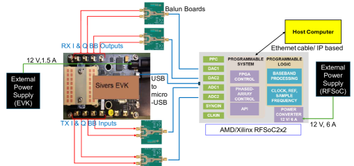
Fig. 1 shows a block diagram of the SDA. It includes a) the 16-element phased-array transceiver [11], b) multiple balun boards [13] for differential to single-ended interfacing, c) the RFSoC for baseband processing [12], d) multiple power supplies, and e) a host computer for running the application.
The phased array is the EVK02001 [11] from Sivers Semiconductors. The evaluation kit (EVK) includes the transceiver chip, packaged with antennas and integrated onto a printed-circuit board (PCB) with additional circuitry for interfacing and power management. The beamforming transceiver uses direct conversion in both RX and TX modes to convert to/from differential analog in-phase (I) and quadrature-phase (Q) baseband (BB) interfaces. The transceiver can be tuned from 24 to 29.5 GHz, supporting multiple FR2 bands.
The array has 16 TX elements and 16 RX elements in 8x2 configurations. Separate TX and RX arrays indicate that the chipset provider avoided the use of transmit/receive switches, likely to improve overall radio-frequency (RF) performance. This comes at the penalty of increased board area for separate antennas and slight misalignment of TX and RX beams; however, these penalties are small at 28 GHz for an 8x2 array. Each element within the phased array has programmable phase shifters that can be custom-defined for 64 different patterns; however, the EVK also comes with pre-defined phase-shifter settings for 21 calibrated patterns scanned from -45 to +45 with 4.5 resolution. The EVK is connected to the RFSoC via a USB interface, and control is established using an API.
The EVK is responsible for the following:
-
1.
Beamforming: Predefined or custom beam patterns are set by programming the phase-shifter values.
-
2.
Signal conditioning: The transceiver provides variable-gain amplification, filtering, and tuning. Key metrics include a 32 dBm EIRP for the TX and a 6 dB noise figure for the RX.
-
3.
Frequency conversion: The RF chain converts between BB signals and mmWave signals, supporting 0.9 GHz instantaneous bandwidth for both I and Q signals independently.
-
4.
Interfacing: Analog differential I and Q signals interface to the RFSoC via baluns for differential inputs.
The RFSoC 2x2 is a single-chip signal-processing platform from AMD/Xilinx [12] that integrates the key subsystems required to implement a software-defined radio (SDR). This includes multiple data converters to digitize BB analog I and Q signals, field programmable gate array (FPGA) logic operating at giga-samples-per-second (GS/s), and integrated processors. The RFSoC uses a Python-based (PYNQ) framework that runs on the included Arm Cortex-A53 64-bit quad processor. This PYNQ-enabled board and its framework are used to develop our custom algorithm to integrate the RFSoC board with the phased-array platform and run operations remotely, leveraging [14, 15].
The RFSoC is responsible for the following tasks:
-
1.
API: Creating an transmission control protocol (TCP)/ internet protocol (IP) based application interface for controlling the SDA and enabling remote-login of users for conducting experiments [14], thereby supporting open-source functionality.
-
2.
Beam management: Programming the radio communication protocols and design of custom logic to interact with phased array via memory registers. These protocols allow one to estimate coverage and discovery delay.
-
3.
Baseband signal/sample generation: Generating the continuous-time BB I and Q signals to be transmitted by the EVK using the baseband samples provided by the host computer or providing the baseband samples by sampling the continuous-time I and Q signals.
II-B RF Link Budget
We calculate the range () as 128 m for a given EIRP of 32 dBm at bore-sight, using the following formula [16]:
| (1) |
where is receive antenna gain, is the wavelength of the signal, is receiver sensitivity, is link margin (here set to 20 dB to accommodate additional losses due to implementation errors), and is atmospheric losses. The free-space path loss (FSPL) for this range is 104 dB, determined by:
| (2) |
Reduced wavelength leads to higher path loss, hence higher gain antennas are desirable to increase the range.
II-C Beam-Pattern Control
The control of the phased array is done dynamically by programming the response of each array element to realize a specific phase shift to form beam patterns according to the standard phased-array theory below:
| (3) |
where is the angle of departure/arrival with respect to the broadside, is the distance between the elements, and where and are the amplitude and phase of the nth element. For each desired pattern, a user-defined antenna weighting vector (AWV) is generated for all phase shifters within the array. These are vector interpolators that realize an element response of , as follows:
| (4) |
where I and Q components are the in-phase and quadrature-phase response of the nth element, controlled with amplifiers.
II-D Software Control and Functionality
The software control is partitioned into three categories, each allowing control of a set of functions. The top layer is the scripts running on the host computer. The API is created on the RFSoC’s PYNQ framework, which serves as an interface to control the hardware via a TCP/\AcIP-based network. The API enables a high-level execution of control commands that are called from top-level scripts. The second and major part of the functionality is handled by the RFSoC board. We set custom IP addresses for the FPGA boards to access the boards and communicate. The RFSoC controls the phased array via a USB interface. The third part is EVK control, that includes TX/RX mode of operation, variable gain setting, phase of antenna elements, number of active elements at a given time, and beamforming control. The partitioning of functions between the servers and the FPGA enables fast execution and flexibility of remote experiments. More details on software mapping of the prototype can be found in [15].
II-E PPDU Design
We adopt the orthogonal frequency-division multiplexing (OFDM)-based physical-layer protocol data unit (PPDU) design discussed in [15] and increase the throughput by supporting higher-order modulation. Baseband processing, channel estimation, and protocol implementation are done using key technologies such as waveform-triggered reception (WTR). As illustrated in Fig. 2, the transmitter encodes data bits along with a preamble for time-frequency synchronization and channel estimation at the receiver. The channel response is estimated based on preamble symbols. The time-domain signals are converted to a baseband frequency domain signal using the digital-to-analog converters (DACs) on the RFSoC. On the receiver end, the decoding process involves synchronization, estimating the non-idealities such as carrier-frequency offset in the received signal, removing the cyclic prefix (CP), estimating the channel parameters, and extracting the payload data.
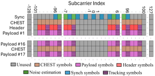
The PPDU supports BPSK, 4-QAM, 16-QAM, and 64-QAM with Gray mapping. Depending on the modulation type, the number of payload bits may not be an integer multiple of the symbol bit length; additionally, the remaining payload bits for the last codeword may not be enough to completely fill it. To resolve these issues, the payload bits are pre-padded with zeroes to fill the remaining modulation symbols and codewords. The payload bits are then post-padded with zeros so that each data subcarrier in the last OFDM payload symbol is filled. All padding information is conveyed in the header field of the PPDU. The payload OFDM symbols use active data subcarriers, where the IDFT size is 256 and the CP size is 64, with an encoding scheme that features -bit codeword. Additionally, the channel encoder uses polar code and cyclic-redundancy check bits are appended to message bits per codeword. An extra chest field occurs every 16 OFDM payload symbols and is used to refresh the channel estimate. Tracking symbols are also used to estimate the common phase error.
The bandwidth of the complex baseband signal can be calculated as (192 active + 8 DC tones)/256, i.e., GHz, where Gsps is the sample rate of the SDA. The data rate of the payload can also be calculated as
| (5) |
where is modulation order and ns is OFDM symbol duration, including the CP. For instance, the data rates for BPSK and 64-QAM are given by Mbps and Gbps, respectively.
III Beam Steering Characterization
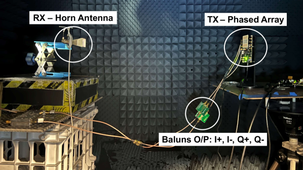
This first set of experiments focuses on understanding the beamforming response of the phased array by evaluating its antenna patterns. Fig. 3 shows the measurement setup inside an anechoic chamber for evaluating the over-the-air performance of the array in transmit mode. We use the EVK as the TX and inject an 800 MHz continuous wave (complex) signal into the baseband of the TX to generate a single-sideband tone at 28.8 GHz. A standard gain horn antenna connected to a spectrum analyzer is placed at a 1.3 m distance and used as the RX. The broadside pattern is first measured while rotating the EVK along the azimuth.
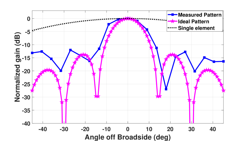
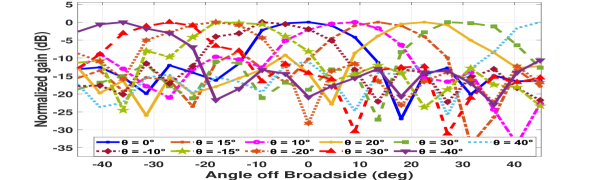
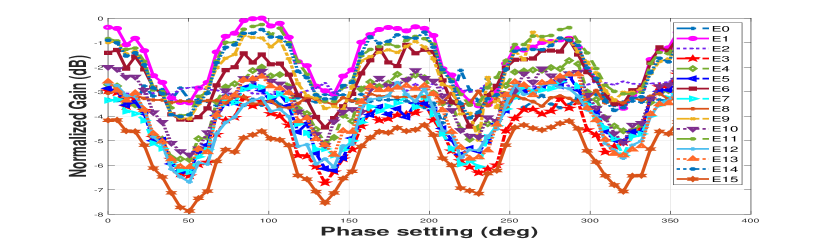
Fig. 4 shows the array pattern normalized to a peak gain of 14 dBi. It is compared to the ideal response of an 8x2 array and an ideal unit-element antenna response with a pattern. As can be seen, there is a notable alignment in the patterns. However, the side lobes are slightly higher than desired. The measured peak-to-null ratio is 17 dB, which indicates that the AWV is not perfectly calibrated. The measured 3 dB beamwidth is 10.
Fig. 5 shows the measured antenna patterns as the beams are steered from -45 and +45. We do not observe any unexpected behavior as the beam is steered; however, we also conclude that better performance, in terms of null depth and side-lobe levels, could be obtained with a better calibrated AWV for these patterns, also stated in [2]. Note that the manufacturer only provides pre-defined AWVs for the 45 range, presumably due to mutual coupling between antennas limiting the performance outside of this range.
Our ultimate goal is to enable arbitrary pattern formation, which necessitates the evaluation and calibration of each individual element in the EVK. Calibration is crucial to equalize gain and phase responses, ensuring uniform performance regardless of antenna configurations. To this end, we extracted the element-by-element response using a built-in self-test technique for phased arrays developed at NC State. This code-modulated embedded test (CoMET) technique uses orthogonal on/off codes [17] per element in the array to modulate a test signal, and these signals are then code multiplexed in free space for TX mode. A simple power detector measures the aggregate response and, in so doing, squares the signal and creates all possible cross-products (or correlations) between elements, each modulated by code products. The codes are selected to have orthogonal code products; hence, all correlations can be extracted. These can be used within a transcendental equation solver in MATLAB to determine each element’s gain and phase response. More details can be found in [18, 17].
The AWVs provided by the manufacturer does not provide calibrated phase settings for all possible phase shifts, but rather settings for particular calibrated patterns. As such, we programmed each phase shifter assuming they had an ideal Cartesian response from (4), using the DACs for the I and Q settings in each phase shifter.
Fig. 6 shows the extracted gain versus ideal phase setting. We observe that the gain fluctuates in a periodic fashion, having maximum gain near the 0/90/180/270 axes, and minimum gain in between. This is not unexpected, as vector interpolators can have such variations, which is why they must typically be calibrated. The other key observation is that the element-to-element variation is within 4-5 dB. These variations can be due to chip, package, and/or antenna variations between elements. Future work for our team is to fully calibrate the EVK using CoMET for all possible phase settings, which will allow the synthesis of arbitrary patterns.
IV Communication Link Measurements
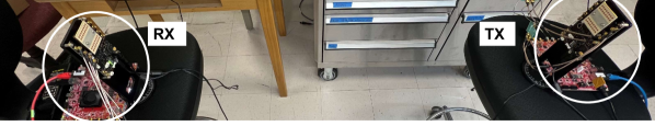
In this experiment, we use the SDA and validate the link performance for multiple beam patterns. The measurements are performed in an indoor environment using a tabletop setup, as shown in Fig. 7. The two SDRs (TX and RX) are placed at a distance of 4.5 m and are controlled by a companion computer over an access point through a TCP/IP based connection. The beam index information is transmitted, as the RX has no information about the beam index at the TX. This experiment uses predefined beams and electronically sweeps these in the azimuthal direction from -45° to +45°.
The transmitter and the receiver have their own set of 21 AWVs. The TX will transmit the beam at each position for a specific time and then change the direction in the next time frame until all scan angles from -45 to +45.
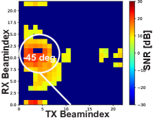
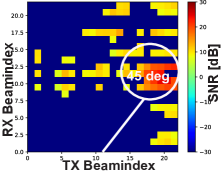
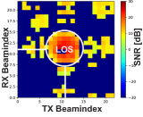
Using this measurement, we evaluated the SNR for each beam pattern on the transmit and receive sides, the data transfer rates, and the quality of the data link in terms of error vector magnitude (EVM). The SNR of the received signal is shown in Fig. 8 across all swept patterns. Each beam-index position corresponds to a scan angle, with 0 at the center for beam-index = 11. The matrix demonstrates that the SNR reaches its peak of 30 dB when the TX and RX beams are perfectly aligned, specifically at line-of-sight (LOS). From this SNR, we note that the EVM of the system must also be -30 dB or lower, consistent with data in [11]. We also see a minimum SNR of 10 dB across all linear sweep positions.
Note that the measurement setup in Fig. 7, is a real-time scenario susceptible to multiple sources of reflections to maintain a link. Notably, a reflected signal is observed at the convergence of RX beam-indices (15-18) and TX beam-indices (3-8) in Fig. 8LABEL:sub@fig:sub3, attributed to the presence of a metal cabinet within the setup. Fig. 8LABEL:sub@fig:sub1-8LABEL:sub@fig:sub2, refer to the SNR pattern when SDA is steered to -45° and +45°, respectively.
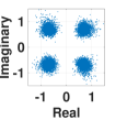
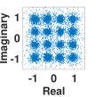
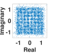
Fig. 9 shows the received symbols plots for 4-QAM, 16-QAM, and 64-QAM after channel equalization. Here, we test our SDA by transmitting an ASCII message as a payload with QAM constellations. In each case, we calculate the log-likelihoods of the coded bits for different constellations, and its corresponding codewords are decoded. For each modulation, the transmitted ASCII message is recovered successfully. In our setup, we observe that some of the subcarriers can fade approximately by 3-6 dB (slight frequency-selective fading within 1.2 GHz bandwidth), which causes noisy symbols in Fig. 9. In the future, we plan to investigate the channel characteristics by using our SDA to improve the reliability of the link. Further improvements to our design may also include higher-order modulations along with different coding strategies, which would further increase the maximum data rate of the system. We also plan to configure these boards with WiFi instead of ethernet cables, allowing us to perform outdoor tests (10 m) to unleash its full potential.
| Reference | [1] | [4, 5, 8, 9] | [6] | [3] | [7] | [2] | [10] | This work |
| Frequency | 24 GHz | 28 GHz | 28 GHz | 28 GHz | 28 GHz | 28 GHz | 26.5-40 GHz | 24-29.5 GHz |
| Bandwidth | 200 MHz | 100 MHz | 100 MHz | NR | 20 MHz | 40 MHz | 20 MHz | 1.2 GHz |
| Elements | 8 | 128 | NR | 8 | 64 | 8 | horn | 16 |
| DSP | X310 | 2974/B200 | RIO | N310 | NI 294xR | M3-Force | N210 | RFSoC 2x2 |
| Range | 100 m | 100 | 7.1 m | NR | NR | NR | 0.7 m | 128 m |
| Beamwidth | NR | NR | NR | 27° | NR | 12° | 26° | 20° |
| Polarization | Single | Dual | Single | Single | Dual | NR | Single | Single |
| Beamforming | Analog | Hybrid | Analog | Digital | Hybrid | NA | NA | Analog |
| Power | NR | NR | NR | NR | NR | NR | NR | 5.5 W |
| Control | GNU radio | API | LabVIEW | MATLAB | LabVIEW | MATLAB | GNU radio | API |
| Interface | GigE | GigE | GigE | GigE | GigE | GigE | GigE | GigE/USB/SPI |
| Data rate | NR | NR | 400 Mbps | NR | NR | NR | NR | 1.613 Gbps |
NA - Not Applicable, NR - Not Reported.
V Conclusion
In this work, we present a low-cost SDA platform. To the best of our knowledge, this is the highest capability and lowest cost open-access SDA for 24-29.5 GHz. Table I summarizes details of performance achieved, compared to existing solutions. This prototype can be used to test new wireless protocols for 5G and advanced 6G systems that will support artificial intelligence and automation applications. We test our developed system by establishing an RF link and characterizing its responses. We evaluated the signal strength received in the presence of multipath components and the array’s response in an over-the-air free-space environment. The received signal strength is highest with an SNR of 30 dB when the transmit and receive beams are aligned with each other. The array beam response shows near-expected side-lobe levels, 3 dB beamwidth of 10 and a scan range of 45.
The developed SDA can be used by researchers to conduct experiments using programmable mmWave radios in real-world environments. This includes waveform development, beamforming algorithms, spectrum monitoring, surveillance, and interference detection. Future work includes completing the calibration of the array for arbitrary pattern synthesis and mounting the SDA to an unmanned aerial system (UAS) for mobile experiments within the AERPAW platform.
VI Acknowledgements
The authors thank Prof. Suresh Venkatesh from NC State University for technical discussions and feedback.
References
- [1] O. Abari, H. Hassanieh, M. Rodreguiz, and D. Katabi, “Poster: A millimeter wave software defined radio platform with phased arrays,” in ACM International Conference on Mobile Computing and Networking, 2016, pp. 419–420.
- [2] J.-H. Deng, S.-K. Liu, C.-J. Liu, C.-C. Hou, C.-Y. Liu, M.-L. Ku, J.-Y. Li, and J. D.-S. Deng, “Design of millimeter wave active array antenna module with embedded system and calibration of software defined radio platform,” in IEEE VTS Asia Pacific Wireless Communications Symposium, 2021, pp. 1–6.
- [3] D. Marinho, R. Arruela, T. Varum, and J. N. Matos, “Software-defined radio beamforming system for 5G/radar applications,” Applied Sciences, vol. 10, no. 20, 2020.
- [4] B. Sadhu and et al., “A 128-element dual-polarized software-defined phased array radio for mm-wave 5G experimentation,” in ACM Workshop on Millimeter Wave Networks and Sensing Systems, 2018, pp. 21–25.
- [5] B. Sadhu, A. Paidimarri, M. Ferriss, M. Yeck, X. Gu, and A. Valdes-Garcia, “A software-defined phased array radio with mmwave to software vertical stack integration for 5G experimentation,” in IEEE MTT-S International Microwave Symposium, 2018, pp. 1323–1326.
- [6] K. Wang, X. Yang, X. Li, C.-K. Went, and S. Jin, “SDR implementation of an end-to-end mmwave testbed based on phased antenna array,” in International Conference on Wireless Communications and Signal Processing, 2019, pp. 1–6.
- [7] M. Chung and et al., “Millimeter-wave massive mimo testbed with hybrid beamforming,” in Asilomar Conference on Signals, Systems, and Computers, 2020, pp. 309–313.
- [8] X. Gu, A. Paidimarri, B. Sadhu, C. Baks, S. Lukashov, M. Yeck, Y. Kwark, T. Chen, G. Zussman, I. Seskar, and A. Valdes-Garcia, “Development of a compact 28-GHz software- defined phased array for a city-scale wireless research testbed,” in IEEE MTT-S International Microwave Symposium, 2021, pp. 803–806.
- [9] T. Chen and et al., “Programmable and open-access millimeter-wave radios in the pawr cosmos testbed,” in ACM Workshop on Wireless Network Testbeds, Experimental evaluation & Characterization, 2022, pp. 1–8.
- [10] M. Jean, M. Yuksel, and X. Gong, “Millimeter-wave software-defined radio testbed with programmable directionality,” in IEEE Conference on Computer Communications Workshops, 2023, pp. 1–8.
- [11] Sivers Semiconductors Evaluation Kit EVK02001. [Online]. Available: https://www.sivers-semiconductors.com/sivers-wireless/wireless-products/evaluation-kits/evaluation-kit-evk02001/
- [12] RFSoC 2x2 Overview. [Online]. Available: https://www.rfsoc-pynq.io/
- [13] “TI.” [Online]. Available: https://www.ti.com/tool/ADC-LD-BB
- [14] A. Şahin, A. P. Ganesh, and A. J. Perre. Project: mmWaveSDR. [Online]. Available: https://github.com/alphansahin/mmWaveSDR/tree/main/design_pynq_28GHz
- [15] A. Şahin, M. L. Sichitiu, and I. Guvenc, “A millimeter-wave software-defined radio for wireless experimentation,” in IEEE International Conference on Computer Communications Workshops, 2023, pp. 1–6.
- [16] M. I. Skolnik, Radar Handbook. McGraw-Hill, 2008.
- [17] S. Almahmoud, Z. Hong, and B. A. Floyd, “Simultaneous phased-array element testing using orthogonal amplitude modulation,” in IEEE International Symposium on Phased Array Systems & Technology, 2022, pp. 01–05.
- [18] Z. Hong, V. Chauhan, S. Schönherr, and B. A. Floyd, “Code-modulated embedded test and calibration of phased-array transceivers,” IEEE Transactions on Microwave Theory and Techniques, vol. 69, no. 3, pp. 1846–1859, 2021.