IEEEexample:BSTcontrol
LA-UR-24-29632 Exploring the relation between transonic dislocation glide and stacking fault width in FCC metals
Abstract
Theory predicts limiting gliding velocities that dislocations cannot overcome. Computational and recent experiments have shown that these limiting velocities are soft barriers and dislocations can reach transonic speeds in high rate plastic deformation scenarios. In this paper we systematically examine the mobility of edge and screw dislocations in several face centered cubic (FCC) metals (Al, Au, Pt, and Ni) in the extreme large-applied-stress regime using MD simulations. Our results show that edge dislocations are more likely to move at transonic velocities due to their high mobility and lower limiting velocity than screw dislocations. Importantly, among the considered FCC metals, the dislocation core structure determines the dislocation’s ability to reach transonic velocities. This is likely due to the variation in stacking fault width (SFW) due to relativistic effects near the limiting velocities.
Los Alamos National Laboratory, Los Alamos, NM, 87545, USA
E-mail: krjones2@uw.edu, kqdang@lanl.gov, dblaschke@lanl.gov, saryuj@lanl.gov, ahunter@lanl.gov
1 Introduction
Since its first discovery by Taylor in 1934, dislocation properties have been extensively studied due to their important role in plasticity. However, there are still unresolved questions about dislocation behaviors, especially under extreme loading conditions such as high applied strain rates. In this regime, one of the key questions is whether dislocations can reach transonic and/or supersonic speeds under sufficiently high applied stress. Some early experiments suggested that there may be a limiting velocity of dislocation movement [1, 2]. However, due to the inherent challenges with tracking dislocations in this extreme regime, the first experimental observation of transonic dislocations only happened recently in diamond [3]. Therefore, a majority of the studies of dislocation behaviors in this regime have relied on theoretical and modeling tools such as molecular dynamics (MD) simulations.
Theoretically, the existence of transonic and supersonic dislocations, which are separated from the subsonic ones by critical velocity “barriers”, was predicted by the steady-state theory of perfect dislocations [4, 5]. Importantly, these velocity barriers have been speculated to be soft limits that can be overcome under extreme conditions [6, 7]. This idea was supported by results from MD simulations for FCC metals such as Ni, Al, and Cu [8, 9, 10, 11, 12, 13, 7, 14, 15], BCC W [16, 17], and HCP Mg [18]. A majority of transonic dislocations are only observed in edge dislocations where the subsonic dislocations asymptotically approach the lowest limiting velocities until some critical stress above which transonic motion becomes possible [8, 11, 12, 13, 7, 14, 15, 18]. On the other hand, for screw dislocations, instabilities in the form of additional dislocation nucleation from the existing partials or homogeneously within the simulation box appeared at higher applied shear stresses (500 MPa) in both FCC and HCP metals [7, 14, 9, 18]. In fact, transonic speeds were only observed in Cu screw dislocations at very low temperatures (10K) [11, 12, 13, 7, 14, 9]. It was suggested that at high temperature, the screw dislocations experience larger phonon drag, which prevents them from overcoming the limiting velocities before instabilities occur [7]. However, it remains unclear which parameters govern the ability of one material system’s dislocation to reach transonic gliding speeds.
One of the challenges is the lack of a systematic study across different material systems. Dislocation motion via MD simulations can be studied using different simulation setups [11, 12, 13, 14, 9]. For instance, there are several methods to apply a shear driving force to move the dislocation such as (i) adding a shear force to the top layer of atoms while fixing the bottom layer of atoms, (ii) applying a shear deformation to the simulation cell, and (iii) applying a velocity to the top layer of atoms to impose a shear strain rate. Moreover, the boundary conditions between fixed versus free boundaries also seem to affect the dislocation mobility at near-sonic velocities [19]. Importantly, while there have been MD studies that investigate the behavior of dislocations in the transonic regime [8, 11, 12, 13, 7, 14, 15, 18], they used different interatomic potentials and material systems which prevents a comprehensive understanding of which parameter affects the ability of dislocations to accelerate beyond the subsonic regime.
Therefore, the goal of this paper is to explore the governing parameters that control if the dislocation can reach transonic velocities. To achieve this, mobilities of dislocations under high applied shear stresses are systematically investigated in FCC metals such as Al, Au, Pt, and Ni. These material systems and the corresponding interatomic potentials are carefully chosen so that the important dislocation properties such as unstable stacking fault (USF) energy, intrinsic stacking fault (ISF) energy, and shear modulus are varied.
2 Methodology: Molecular Dynamics Simulations
MD simulations are performed using the classical molecular dynamics simulation code LAMMPS [20] and visualized using the Open Visualization Tool (OVITO) [21]. Table 1 shows the list of interatomic potentials used in this work with important material properties for dislocations such as (average) shear modulus, ISF energy, USF energy, and equilibrium stacking fault widths (SFW) (which were determined for edge dislocations at 0K). Only FCC metals with the same functional form for the interatomic potentials are used to reduce the complexity of the comparison. For Pt, due to the lack of reasonable embedded atom model (EAM) potentials, a modified EAM (MEAM) is used instead. Importantly, the four FCC material systems and corresponding interatomic potentials are specifically chosen to have a wide range of values for shear modulus, ISF energy, USF energy, and equilibrium SFW.
| Metal [Potential] | Lattice Constant (Å) | (GPa) | (GPa) | (GPa) | (GPa) | Intrinsic SFE (mJ/m2) | Unstable SFE (mJ/m2) | Density (g/cm3) | Equilbrium SFW (Å) |
| Ni [23] | 3.52 | 247.86 | 147.83 | 124.84 | 87.2 | 125.25 | 367.8 | 8.94 | 31.37 |
| Pt [24] | 3.92 | 358.12 | 253.51 | 77.55 | 66.4 | 110 | 596.0 [25] | 21.55 | 16.20 |
| Au [26] | 4.07 | 201.65 | 169.53 | 45.97 | 30.8 | 42.58 | 91.69 | 19.4 | 67.04 |
| Al [27] | 4.05 | 116.82 | 60.12 | 31.66 | 30.3 | 113.77 | 149.72 | 2.70 | 22.55 |
| Metal | Dislocation Type | 1st Limiting Velocity (km/s) | 2nd Limiting Velocity (km/s) | |||
|---|---|---|---|---|---|---|
| Ni | Edge | [11] | [111] | [01] | 2.37 | 3.74 |
| Screw | [01] | [111] | [2] | 3.05 | N/A | |
| Pt | Edge | [11] | [111] | [01] | 1.55 | 1.90 |
| Screw | [01] | [111] | [2] | 1.76 | N/A | |
| Au | Edge | [11] | [111] | [01] | 0.91 | 1.54 |
| Screw | [01] | [111] | [2] | 1.21 | N/A | |
| Al | Edge | [11] | [111] | [01] | 3.24 | 3.42 |
| Screw | [01] | [111] | [2] | 3.36 | N/A |
To model the dislocation mobility, simulation cells with specific orientations are used for edge and screw dislocations as shown in Table 2. Table 2 also includes the first two limiting velocities for the edge and screw dislocations determined by [29, 7]
| (1) |
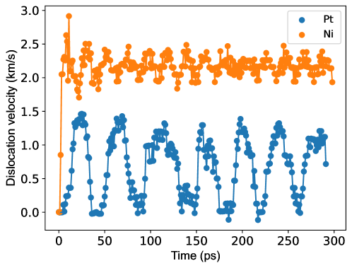
where denotes the material density and . The simulation box is approximately 16 x 52 x 550 Å along the , , and directions, respectively. Periodic boundary conditions were applied along the and directions so the dislocation can glide in and out of the simulation box without encountering barriers. Fixed boundary conditions are applied along the direction with appropriate pre-strain to alleviate stress caused from thermal expansion. A single dislocation is inserted at the center of the simulation box using the Volterra displacement field with appropriate boundary treatment as detailed in Refs. [30, 31]. Shear forces are applied to the top layer atoms to move the dislocations. Once the dislocation motion reaches equilibrium, the dislocation position and SFWs are tracked and determined by using the common neighbor analysis in LAMMPS [20] to identify perfect and defected atoms. While this method is efficient, as temperature and stress increased there were some areas where the lattice shifted enough due to lattice vibrations that it was no longer considered a FCC structure, which complicates the dislocation core region tracking. Data points influenced by this are removed from the analysis. The average velocities and SFWs are recorded only after the dislocation reaches steady state (after 50 ps) for all cases except at 100K for both edge and screw dislocations in Pt where the full range of data (0 to 300 ps) is included. For these two cases, the dislocation motion transitions into stick-slip behavior instead of slip as seen in Fig. 1. Understandably, this will slightly overestimate the error for these two cases. Importantly, the averaged velocities do not vary significantly regardless of ranges of recorded data. In order to keep the temperature constant, a Nosé-Hoover type thermostat and barostat were used [32] as described in Ref. [31]. This allows slight changes in temperature while still keeping the temperature within a few degrees of the target. Temperature effects are considered by using two temperatures at 10 and 100K. The applied stresses are increased until the dislocation achieves transonic motion or the simulation exhibits instabilities.
3 Results
3.1 Mobility of screw dislocations
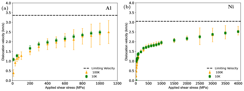
Figure 2 (a)–(d) shows the mobility curves for screw dislocations in Al, Ni, Au, and Pt. Compared to Ni and Al, Au and Pt dislocations are less mobile. The lower mobilities of Au could be due to the relatively lower ISF energy and thus larger dislocation core structures compared to Al and Ni [33]. Among the four, Pt dislocations are extremely immobile with dislocation glide observed only for applied stress greater than 2.25 GPa at 10K and greater than 1.5 GPa at 100K. The significantly higher Peierls stress of Pt dislocations could be due to the combination of high shear modulus (shown in Table 1) and small equilibrium stacking fault width according to the analytical Peierls-Nabarro model. For the same applied shear stress, the dislocation velocities at higher temperature (100K) also fluctuate more compared to the ones at 10K.
For each material, the mobility curve contains two distinct regimes of phonon and radiative drag. As the applied stress increases, the dislocation velocities start to plateau below the limiting velocities shown in Table 2. Higher applied shear stresses result in nucleation of additional dislocations or defects that prevent the proper tracking and determination of dislocation velocities. Importantly, no transonic jump is observed for screw dislocations, though the highest screw dislocation velocity observed in Au at 10K barely exceeds the calculated limiting velocity (which on the other hand is still within the error bars). For the other three FCC metals, no transonic dislocations are found. This result is consistent with previous MD simulations for screw dislocations where only transonic dislocation motion is observed in Cu at very low temperature (10K) [29].
3.2 Mobility of edge dislocations
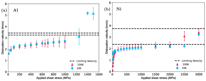
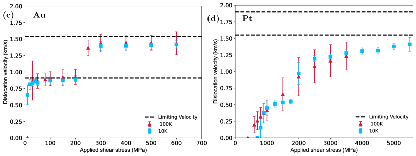
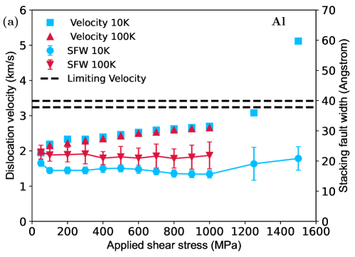
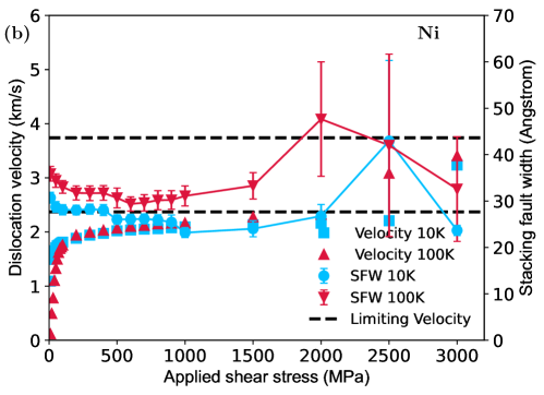
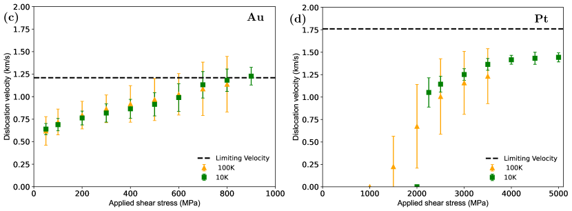
Figure 3 shows the mobility curves for edge dislocations in Al, Ni, Au, and Pt. Overall, edge dislocations for all considered FCC metals are more mobile than screw dislocations. Similar to screw dislocations, the mobility of edge dislocations also scale linearly with applied shear stress at low velocities and eventually plateau at or near the limiting velocities as the stress increases. However, unlike screw dislocations, transonic and supersonic velocities are observed in edge dislocations for large applied shear stresses. For Al, there is a jump in the dislocation velocity to the transonic regime at 10K with applied shear stress of 1.3 GPa, but there was no jump at 100K. At 100K, additional dislocations start to form, glide, and interact with the existing edge dislocation. This is different from previous MD simulations by Olmsted et al. [9] where the authors observed transonic speed of edge dislocations in Al at higher temperature (K). This is due to the differences in the utilized interatomic potentials which will be discussed in the next section. As shown in Fig. 3, Au and Pt edge dislocations have a lower mobility compared to Al and Ni ones. Both reach velocities of approximately 1.4 km/s compared to 5 and 3.24 km/s for Al and Ni dislocations, respectively. In particular, Pt dislocations are less mobile compared to the other three materials and only start gliding with applied shear stress above 600 and 300 MPa at 10 and 100 K, respectively. Importantly, even though the Pt edge dislocation is much more mobile compared to its screw counterpart, it also does not reach transonic velocity even at extremely high applied shear stress of 5 GPa. Above this shear stress, instabilities occur via nucleation of additional dislocations. On the other hand, the Au edge dislocation does not only cross over the limiting velocity at applied shear stress greater than 200 MPa but also comes close to the limiting velocity.
In order to understand the behavior of the dislocation core structure as the dislocations reach the limiting velocities, Fig. 4 (a)–(b) shows the mobility curves and SFWs of Al and Ni edge dislocations, respectively. Initially, the SFW of the Al edge dislocation slightly reduces until the dislocation velocities reach approximately 2.7 km/s. At 1.25 GPa applied shear stress where the dislocation jumps to the transonic regime, the SFW slightly increases. For Ni, the dislocation velocity jumps to the transonic regime (about 3.27 km/s) at an applied shear stress of 2 GPa and 2.5 GPa for temperatures of 10 and 100K, respectively, as shown in Fig. 4 (b). The transonic dislocation motion is consistent with previous MD results for edge dislocations in Ni using a different EAM potential [9]. The dislocation velocity jump happens at a lower stress for higher temperatures which could be due to the larger dislocation core as the temperature increases [34, 35]. Similar to Al, the Ni edge dislocation also reduces its SFW at first up to the velocity of about 2.09 km/s. From there, the SFW increases as the dislocation gets closer to the limiting velocities. However, unlike Al, once the dislocation reaches transonic speed, its SFW contracts. As they transition into the transonic regime, Ni edge dislocations also contract and extend more during their glide motions compared to the Al edge dislocations, which results in higher standard deviations in SFWs shown in Fig. 4.
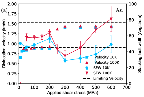
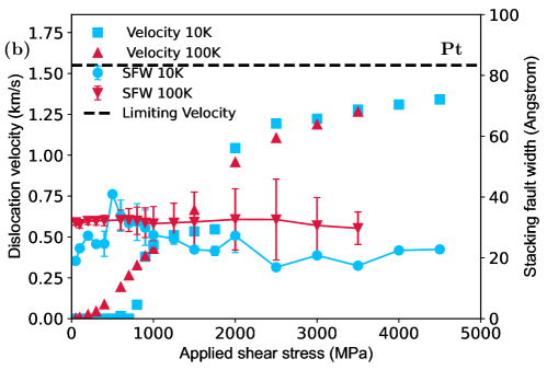
Similarly, Fig. 5 shows the mobility curves and SFWs of Au and Pt edge dislocations, respectively. For Pt edge dislocations, the SFW at 100K remains relatively constant. At a lower temperature of 10K, the SFW increases up to an applied shear stress of 600 MPa, where the edge dislocation starts to move. Then, the SFW reduces back to the previous values and remains constant as the applied shear stress increases. On the other hand, the SFW of Au edge dislocations at both 10K and 100K reduces initially, then increases as the velocities approaches the limiting velocity of 0.91 km/s. As the dislocation velocities cross over this limiting velocity, the SFW reduces again until the applied shear stress approaches 300 MPa. For applied shear stresses greater than 300 MPa, the Au edge dislocation core starts to widen again as its velocity approaches the limiting velocity of 1.54 km/s. The expansion and constriction of the SFW for moving dislocations at different velocities is likely due to the interplay between dislocation drag and relativistic effects [36].
4 Discussion
4.1 Variations in dislocation stacking fault width as the velocity becomes transonic
The evolution of the SFWs seen in this study as the edge dislocations glide with subsonic to transonic velocities can be explained by the effects of stress orientation (also known as the effects of non-Schmid stress) and relativistic effects on dislocation core structures. The former relates to the effects of a stress field on the mobility of the Shockley partials that bound the stacking fault. If the orientation of the stress results in a larger force acting on the leading partial than the trailing partial, the dislocation core widens. Conversely, when the resulting force on the trailing partial is higher, the dislocation core contracts. This stress orientation effect was first noted by Nabarro [37] and has been observed in many previous MD simulation studies [36, 38, 39, 40]. Among the non-Schmid stresses, the Escaig stress, which is the resolved shear stress within the slip plane perpendicular to the Burgers vector, greatly influences the widening and narrowing of the dislocation core, especially during cross-slip for screw dislocations [41].
On the other hand, the relativistic effect influences the dislocation core structure when the dislocation velocity approaches the limiting velocities, similar to Einstein’s theory of relativity for particles approaching the speed of light [36, 42]. As the speed increases up to the Rayleigh wave speed, the interaction force between the screw components decreases while it increases for the edge components. Hirth and Lothe determined the SFWs between partials in FCC and BCC metals via a Lagrangian formulation. They found that a screw dislocation core in FCC metals would constrict with increasing speed until it reaches the transverse sound speed where the trend is reversed and the dislocation core widens and eventually splits apart at the transverse sound speed [43]. For dissociated edge dislocations approaching the Rayleigh wave speed, the attractive force between the opposite sign screw components will decrease and the repulsive force between the same signed edge components will increase [44]. This leads to the extension of the SFW as the speed approaches the Rayleigh wave and limiting speed. Once the dislocation’s speed surpasses the limiting velocities, this relativistic effect is removed. As a result, the dissociated edge dislocations constrict as seen in Figs. 4 and 5 for Ni and Au, respectively. For Au, the SFW expands again once the dislocation’s velocity approaches the limiting velocity. To the authors’ knowledge, this is the first validation of the relativistic effects on edge dislocation core structure that was previously proposed in theory [44, 43].
4.2 Governing parameters for transonic dislocation motion
The MD results in this work show certain trends for transonic dislocation motion behavior:
- 1.
-
2.
Transonic motion is more frequently observed for FCC metals with large SFWs.
These two results can be rationalized by understanding how transonic motion can be achieved. There are three intertwined factors that control this process: drag coefficient, instability, and limiting velocities, which depend on material properties such as stacking fault energies and elastic constants. For example, the drag coefficient is sensitive to the shear modulus [45]. The instability caused by nucleation of additional dislocations depends on the USF energy. Finally, limiting velocities have been shown in previous studies [29] to be dependent on the elastic constants. However, it is most important to note that any unfavorable values of these parameters can prevent the transonic motion of dislocations. For instance, a favorable drag coefficient and low limiting velocities can still fail to achieve dislocation transonic motion if the stress for instabilities to occur is too low (i.e. before the stress required for transonic motion can be reached).
Based on these three parameters, the first trend can be explained. For FCC metals, screw dislocations tend to have higher limiting velocities (see Table 2) but lower mobilities than edge dislocations. This indicates a lower driving force and lower required target velocity for edge dislocations to achieve transonic motion compared to screw dislocations. Note that while it is more challenging for screw dislocations to achieve transonic motion, it is still possible. For example, transonic screw dislocations have been observed in Cu [7] at low temperature. In this study, a low-temperature Au screw dislocation also approached the limiting velocity within .
For the second trend, the effects of SFWs on the feasibility of dislocations to achieve transonic motion is clearly shown in this work. Specifically, Pt edge dislocations, with the smallest equilibrium SFW as shown in Table 1, do not reach transonic velocities. Similarly, Al edge dislocations, with the smallest equilibrium SFW, only reach transonic velocity at low temperatures (namely 10 K). On the other hand, Au and Ni edge dislocations with larger equilibrium SFWs both reach transonic velocities at both 10 and 100K. Small SFWs are equivalent to large ISF and USF energies as shown in previous studies [46, 31] where the dislocation core width is proportional to the product between these two stacking fault energies. With these large stacking fault energies, it is likely that the small SFWs in Pt dislocations (and Al dislocations to some extent) are less likely to expand when approaching the limiting velocities, which prevents them from crossing over to the transonic regime. Based on this, one can determine if a material system can achieve transonic dislocation velocity based on the SFW, ISF, and USF energies.
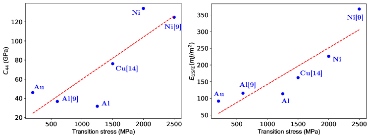
Predicting where and when the dislocations cross over to the transonic regime remains challenging. Figure 6 shows the transition stresses, which are the lowest stress for the dislocations to move at velocities greater than a limiting velocity, at 100K and corresponding material properties/parameters. MD simulation data from [9] for Ni (100K) and Al (216K) as well as [14] for Cu (10K) are also included. While the transition stress for FCC edge dislocations is generally proportional to both the and the USF energy, there was not a clear relationship between them. Attempts to connect to other parameters also provide no clear trends with the transition stresses. This is to be expected since the transonic dislocation motion relies on the interplay between three parameters as mentioned earlier.
5 Conclusions
In conclusion, the transonic motion of dislocations in FCC metals are systematically studied using MD simulations of edge and screw dislocations. It was found that transonic velocities are easier to achieve by edge dislocations compared to screw dislocations due to their higher mobilities and lower limiting velocities. Moreover, the dislocation core is found to widen as the edge dislocation approaches the limiting velocities and constrict back to normal once the dislocation moves at the transonic velocities, which is due to the relativistic effects. Importantly, it is also found that the dislocation’s ability to reach transonic velocities is proportional to its SFW. While this study only focuses on FCC metals, these results highlight the importance of the dislocation core structure to dislocation mobility in the extreme regime.
Acknowledgements
This work was supported by the Advanced Technology Development and Mitigation (ATDM) project and the Physics and Engineering Models (PEM) Materials project within the Advanced Simulation and Computing (ASC) Program of the U.S. Department of Energy under contract 89233218CNA000001. This research used resources provided by the Los Alamos National Laboratory Institutional Computing Program, which is supported by the U.S. Department of Energy National Nuclear Security Administration under Contract No. 89233218CNA000001.
References
- [1] V. R. Parameswaran and J. Weertman, “Dislocation mobility in lead and Pb-In alloy single crystals,” Metallurgical Transactions, vol. 2, no. 4, pp. 1543–1916, 1971.
- [2] J. Weertman, T. Vreeland, and K. M. Jassby, Dislocation Mechanics at High Strain Rates. Boston, MA: Springer US, 1973, pp. 319–333.
- [3] K. Katagiri, T. Pikuz, L. Fang, B. Albertazzi, S. Egashira et al., “Transonic dislocation propagation in diamond,” Science, vol. 382, no. 6666, pp. 69–72, 2023.
- [4] J. Weertman, “Moving dislocations in a shock front,” in Shock Waves and High-Strain-Rate Phenomena in Metals: Concepts and Applications. Springer, 1981, pp. 469–486.
- [5] P. Rosakis, “Supersonic dislocation kinetics from an augmented Peierls model,” Physical Review Letters, vol. 86, no. 1, pp. 95–98, 2001.
- [6] X. Markenscoff and S. Huang, “Analysis for a screw dislocation accelerating through the shear-wave speed barrier,” Journal of the Mechanics and Physics of Solids, vol. 56, no. 6, pp. 2225–2239, 2008.
- [7] D. N. Blaschke, J. Chen, S. Fensin, and B. A. Szajewski, “Clarifying the definition of ‘transonic’ screw dislocations,” Philosophical Magazine, vol. 101, no. 8, pp. 997–1018, 2021.
- [8] S. Groh, E. B. Marin, M. F. Horstemeyer, and D. J. Bammann, “Dislocation motion in magnesium: a study by molecular statics and molecular dynamics,” Modelling and Simulation in Materials Science and Engineering, vol. 17, no. 7, p. 075009, 2009.
- [9] D. L. Olmsted, L. G. Hector Jr, W. A. Curtin, and R. J. Clifton, “Atomistic simulations of dislocation mobility in Al, Ni and Al/Mg alloys,” Modelling and Simulation in Materials Science and Engineering, vol. 13, no. 3, pp. 371–388, 2005.
- [10] N. Daphalapurkar, J. Wilkerson, T. Wright, and K. Ramesh, “Kinetics of a fast moving twin boundary in nickel,” Acta Materialia, vol. 68, pp. 82–92, 2014.
- [11] J. Marian and A. Caro, “Moving dislocations in disordered alloys: Connecting continuum and discrete models with atomistic simulations,” Physical Review B, vol. 74, p. 024113, 2006.
- [12] H. Tsuzuki, P. S. Branicio, and J. P. Rino, “Molecular dynamics simulation of fast dislocations in copper,” Acta Materialia, vol. 57, no. 6, pp. 1843–1855, 2009.
- [13] S. Peng, Y. Wei, Z. Jin, and W. Yang, “Supersonic screw dislocations gliding at the shear wave speed,” Physical Review Letters, vol. 122, p. 045501, 2019.
- [14] E. Oren, E. Yahel, and G. Makov, “Dislocation kinematics: a molecular dynamics study in Cu,” Modelling and Simulation in Materials Science and Engineering, vol. 25, no. 2, p. 025002, 2016.
- [15] J. A. Young Vandersall and B. D. Wirth, “Supersonic dislocation stability and nano-twin formation at high strain rate,” Philosophical Magazine, vol. 84, no. 35, pp. 3755–3769, 2004.
- [16] P. Gumbsch and H. Gao, “Dislocations faster than the speed of sound,” Science, vol. 283, no. 5404, pp. 965–968, 1999.
- [17] Q. Li and S.-Q. Shi, “Dislocation jumping over the sound barrier in tungsten,” Applied Physics Letters, vol. 80, no. 17, pp. 3069–3071, 2002.
- [18] K. Dang, D. N. Blaschke, S. Fensin, and D. J. Luscher, “Limiting velocities and transonic dislocations in Mg,” Computational Materials Science, vol. 215, p. 111786, 2022.
- [19] T. Duong and M. J. Demkowicz, “Resonance with surface waves induces forbidden velocity bands in dislocation glide,” Journal of the Mechanics and Physics of Solids, vol. 180, p. 105422, 2023.
- [20] A. P. Thompson, H. M. Aktulga, R. Berger, D. S. Bolintineanu, W. M. Brown et al., “LAMMPS - a flexible simulation tool for particle-based materials modeling at the atomic, meso, and continuum scales,” Computer Physics Communications, vol. 271, p. 108171, 2022.
- [21] A. Stukowski, “Visualization and analysis of atomistic simulation data with OVITO-the Open Visualization Tool,” Modelling and Simulation in Materials Science and Engineering, vol. 18, no. 1, p. 015012, 2010.
- [22] D. N. Blaschke, “Averaging of elastic constants for polycrystals,” Journal of Applied Physics, vol. 122, p. 145110, 2017.
- [23] Y. Mishin, D. Farkas, M. J. Mehl, and D. A. Papaconstantopoulos, “Interatomic potentials for monoatomic metals from experimental data and ab initio calculations,” Physical Review B, vol. 59, pp. 3393–3407, 1999.
- [24] B.-J. Lee, J.-H. Shim, and M. I. Baskes, “Semiempirical atomic potentials for the fcc metals Cu, Ag, Au, Ni, Pd, Pt, Al, and Pb based on first and second nearest-neighbor modified embedded atom method,” Physical Review B, vol. 68, p. 144112, 2003.
- [25] X.-M. Wei, J.-M. Zhang, and K.-W. Xu, “Generalized stacking fault energy in FCC metals with MEAM,” Applied Surface Science, vol. 254, no. 5, pp. 1489–1492, 2007.
- [26] G. Grochola, S. P. Russo, and I. K. Snook, “On fitting a gold embedded atom method potential using the force matching method,” The Journal of Chemical Physics, vol. 123, no. 20, p. 204719, 2005.
- [27] R. R. Zope and Y. Mishin, “Interatomic potentials for atomistic simulations of the Ti-Al system,” Physical Review B, vol. 68, p. 024102, 2003.
- [28] D. N. Blaschke, “PyDislocDyn,” [Computer Software] https://doi.org/10.11578/dc.20180619.15, 2018–2024.
- [29] D. N. Blaschke, “How to determine limiting velocities of dislocations in anisotropic crystals,” Journal of Physics: Condensed Matter, vol. 33, no. 50, p. 503005, 2021.
- [30] K. Dang and D. Spearot, “Pressure dependence of the Peierls stress in aluminum,” JOM, vol. 70, no. 7, pp. 1094–1099, 2018.
- [31] K. Dang, D. Bamney, K. Bootsita, L. Capolungo, and D. E. Spearot, “Mobility of dislocations in aluminum: Faceting and asymmetry during nanoscale dislocation shear loop expansion,” Acta Materialia, vol. 168, pp. 426–435, 2019.
- [32] S. Melchionna, G. Ciccotti, and B. L. Holian, “Hoover NPT dynamics for systems varying in shape and size,” Molecular Physics, vol. 78, no. 3, pp. 533–544, 1993.
- [33] M. Mills and T. Neeraj, “Dislocations in metals and metallic alloys,” in Encyclopedia of Materials: Science and Technology, K. J. Buschow, R. W. Cahn, M. C. Flemings, B. Ilschner, E. J. Kramer, S. Mahajan, and P. Veyssière, Eds. Oxford: Elsevier, 2001, pp. 2278–2291.
- [34] X. Zhang, B. Grabowski, F. Körmann, A. V. Ruban, Y. Gong, R. C. Reed, T. Hickel, and J. Neugebauer, “Temperature dependence of the stacking-fault Gibbs energy for Al, Cu, and Ni,” Physical Review B, vol. 98, no. 22, p. 224106, 2018.
- [35] X. Li and S. Schönecker, “First-principles prediction of the stacking fault energy of gold at finite temperature,” Acta Materialia, vol. 135, pp. 88–95, 2017.
- [36] Z. Q. Wang and I. J. Beyerlein, “Stress orientation and relativistic effects on the separation of moving screw dislocations,” Physical Review B, vol. 77, p. 184112, 2008.
- [37] F. R. N. Nabarro, “Extended dislocations and the Schmid law of resolved shear stress,” The Philosophical Magazine A, vol. 14, no. 130, pp. 861–866, 1966.
- [38] K. Kang, J. Yin, and W. Cai, “Stress dependence of cross slip energy barrier for face-centered cubic nickel,” Journal of the Mechanics and Physics of Solids, vol. 62, pp. 181–193, 2014.
- [39] S. Aubry and D. A. Hughes, “Reductions in stacking fault widths in fcc crystals: Semiempirical calculations,” Physical Review B, vol. 73, no. 22, p. 224116, 2006.
- [40] K. Dang, D. Bamney, L. Capolungo, and D. E. Spearot, “Mobility of dislocations in aluminum: The role of non-Schmid stress state,” Acta Materialia, vol. 185, pp. 420–432, 2020.
- [41] J. Bonneville and B. Escaig, “Cross-slipping process and the stress-orientation dependence in pure copper,” Acta Metallurgica, vol. 27, no. 9, pp. 1477–1486, 1979.
- [42] J. Eshelby, “Uniformly moving dislocations,” Proceedings of the Physical Society. Section A, vol. 62, no. 5, p. 307, 1949.
- [43] J. Hirth and J. Lothe, “Interactions between moving dislocations,” in Dislocation Dynamics, A. R. Rosenfield, G. T. Hahn, A. L. Bement, and R. J. Jaffee, Eds. McGraw-Hill, 1968.
- [44] J. Weertman, “Fast moving edge dislocations on the (111) plane in anisotropic face-centered-cubic crystals,” Journal of Applied Physics, vol. 33, no. 5, pp. 1631–1635, 1962.
- [45] D. N. Blaschke, “Velocity dependent dislocation drag from phonon wind and crystal geometry,” Journal of Physics and Chemistry of Solids, vol. 124, pp. 24–35, 2019.
- [46] A. Hunter, I. J. Beyerlein, T. C. Germann, and M. Koslowski, “Influence of the stacking fault energy surface on partial dislocations in fcc metals with a three-dimensional phase field dislocations dynamics model,” Physical Review B, vol. 84, no. 14, p. 144108, 2011.