Mode hitching in traveling-wave optical parametric amplification
Abstract
Optical parametric amplifiers (OPAs) in traveling wave configuration can generate localized spatial quantum correlations between a signal and an idler beam, a useful resource for quantum imaging. This study focuses on the classical transverse dynamics of the signal and idler beams when they propagate in a generic thick OPA at a nominally small angle. It shows that the beams tend to copropagate while maintaining a fixed separation, a phenomenon that we term hitching. We provide a model for hitching, validated by a numerical simulation, and we provide an experimental demonstration using four-wave mixing (4WM) in a hot atomic vapor. It shows that the OPA gain is the primary influence on the final hitching distance. These results have implications for the generation of multi-spatial-mode squeezed light for quantum imaging applications, where the exact spatial correspondence between the quantum fluctuations of the signal and the idler is of prime importance.
I Introduction
Optical parametric amplification (OPA) is at the heart of quantum-state production [1, 2]. In OPA, a signal optical field is amplified simultaneously with the creation of an idler field, through non-linear coupling with one or more additional pumping fields. The coherence of the process ensures that signal and idler fields, here referred to as twin beams, are created and correlated in a shared quantum state. This can be used to create photon pairs that are entangled in polarization [3], position and momentum [4], or fields that are entangled or squeezed in quadrature [5], or squeezed in intensity difference [6].
In quantum imaging, one typically seeks to engineer squeezing or entanglement independently at any position in a transverse section of the optical field [7, 8, 9, 10]. This can be done with a traveling wave amplifier that relies on a thin nonlinear medium. The medium naturally couples the signal and idler fields locally, creating spatially localized quantum correlations. An equivalent statement is that the amplifier couples arbitrarily narrow modes of the signal and the idler at any position of the thin medium. Having a thin medium removes the more complicated dynamics such as the effects of propagation [11, 12]. This could lead to the correlated fields to spatially separate while being created. In practice, the medium must have a finite length to generate a finite amplification gain. In particular, quadrature squeezing and entanglement typically require a medium much longer than the wavelength of the light. For a correspondingly thick medium, even if the fields are strictly copropagating, diffraction puts a lower limit on the width of the signal and idler beams that can be coupled, leading to the emergence of a coherence area [9, 11]. In this work, we go one step further and look at the impact of phase conjugation on the joint propagation of the signal and idler modes, as well as the possible modification of the coherence area.
The issue of propagation arises when the signal and idler beams propagate with a small angle between them. This is a common situation: when pumping the medium with one or several plane waves along , the conservation of transverse momentum, which is null, makes the propagation of the twin beams symmetric with respect to the direction. This becomes relevant when the amplification is phase-matched for a finite angle between the twin beams and the pumping direction. It raises the question of what happens when initially narrow twin beams, with a size as low as the coherence area, separate while propagating in the gain medium. Since they stimulate the nonlinear process and get amplified while generating their partner beam along their separate trajectories, the expectation is the production of wide-area signal and idler fields. We show here that for a small angle between the signal and the idler, this is not the case. The signal and idler effectively copropagate, in apparent violation of the phase-matching condition, at a fixed distance from each other. In the following, we refer to this phenomenon as hitching. The width of the twin beams stays roughly constant.
It is important to note that the effect described here is separate from the walk-off effect observed in type II parametric down-conversion (PDC) due to the birefringence of the nonlinear medium. In this case, a mismatch between the Poynting vector and the wave-vector forces the signal to walk off the pump beam [13, 3]. The effect presented here may be smaller in magnitude and occurs even in isotropic media. It would likely be masked by the transverse walk-off in a typical birefringent crystal.
Paraxial propagation of twin beams in an OPA has been considered in the context of diffraction and absorption control [14, 15]. Cancellation of diffraction on the signal beam during is achieved when the angular dispersion of the beam is approximately zero, that is to say the accumulated phase of a plane wave on traversal of the amplifying medium does not depend on the transverse wave-vector. This effect may be realized for specific values of the complex direct and cross susceptibilities of the medium for the twin beams [15]. The problem we are considering here is different. Starting from OPA parameters which are known to produce highly quantum states of light, namely low absorption on both twin beams and high gain, we look at the evolution of the average position of the beams during propagation in the medium, and show that the apparent trajectory of the beams upon amplification deviates from a straight line.
The paper is organized as follows. Section II introduces a basic theoretical model of the hitching effect, which is then solved numerically. This allows us to extract the basic physical characteristics of the phenomenon. Section III describes an implementation of OPA based on 4-wave mixing in a hot atomic vapor, and the experimental setup that allows us to measure the hitching effect. Section IV presents our experimental results and shows how the hitching distance depends simply on the amplification gain. We conclude by looking at the implications of these results on the generation of multi-spatial mode squeezed light for quantum imaging.
II Model
The basic physics of the hitching effect is simple. Parametric amplification is stimulated by both the signal and the idler. As a consequence, it occurs with a higher gain in regions where both twin beams are present, i.e., where the signal and the idler overlap. While the phase-matching condition pulls the twin beam apart, preferential amplification in their overlap region keeps their average separation bounded, so that they propagate in lockstep.
In this section, we look at the minimum theoretical model of twin-beam generation that shows transverse hitching and its dependency on experimental parameters. To this effect, we consider a pair of quasi-degenerate coupled beams of unspecified polarization, created by optical parametric amplification, here referred to as modes 1 and 2. This is typically produced by down-conversion or four-wave mixing in a traveling-wave configuration. However, we keep it generic at this stage. To rule out walk-off effects due to birefringence, we only consider an isotropic medium with a scalar index of refraction, possibly complex to represent absorption. Linear or nonlinear refraction effects are also annulled by making the medium spatially homogeneous, a condition that would be experimentally achieved by using wide pumping beams. Since we are interested in walk-off effects between the coupled beams, we assume them to be broadly copropagating to first approximation, possibly with a small angle between them. In the paraxial approximation, their respective electrical field amplitudes can be written as
| (1) | ||||
| (2) |
To simplify the problem, we assume that the beams have similar frequencies , and therefore similar wave-vectors . The beams propagate along the direction in a nonlinear medium placed between and , and we only consider the transverse direction. In real space, and interact locally via the cross-susceptibility . In the reciprocal transverse space, couples the slowly-varying envelopes and , which propagate according to
| (3) |
where is the paraxial phase responsible for diffraction. The coefficients and are proportional to the linear susceptibilities for modes 1 and 2, and account for single beam propagation effects, such as absorption and refraction. The cross-coupling is given by where is the cross-susceptibility of the medium, which has to be real for efficient amplification. The amplification couples mode 1 transverse momentum with mode 2 transverse momentum . When the process is stimulated by a seed field in mode 1 at position , the solutions to Eq. (3) inside the medium are
| (4) | ||||
| (5) |
where
| (6) | ||||
| (7) | ||||
| (8) |
This set of equations allows us to propagate both beams in reciprocal transverse space. We first consider the case of a fully transparent medium, which is achieved when and are real. In the absence of refraction, that is, when , the nonlinear process is phase-matched for fully copropagating beams. In other words, the gain, defined by the ratio , is maximum for . In the context of imaging, it is advantageous to be able to spatially separate the two beams. It can be achieved in the far field when they propagate at a small angle in the – plane. To make the amplifier efficient in this geometry, we introduce a small angle between the phase-matched directions by adding some refraction on the two beams, that is, by giving finite real values to and . From Eqs. (4–8), it is clear that it does not matter how the refraction is distributed between the modes.
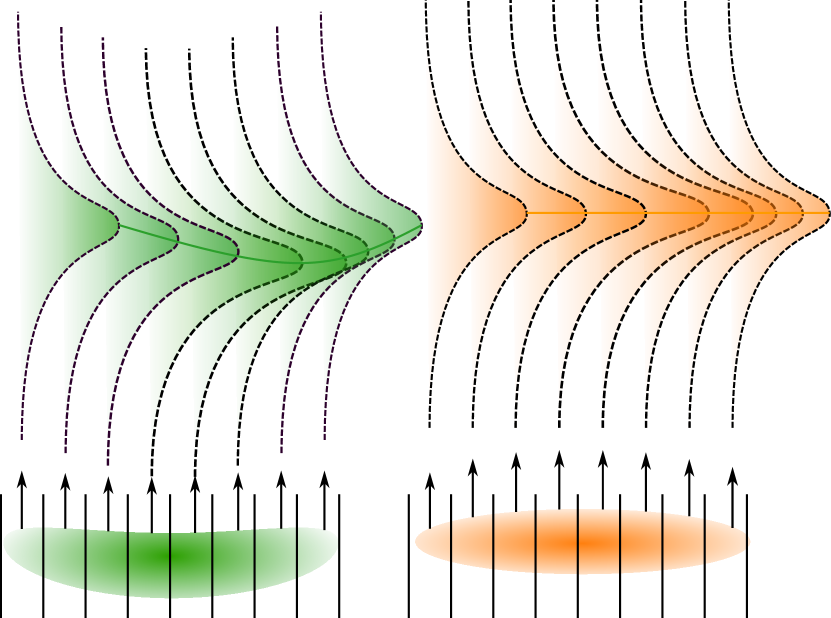
The propagation of beams of finite transverse sizes is achieved by propagating their plane-wave components according to Eqs. (4) and (5). Fig. 1 shows how such beams propagate in a finite size medium, when the optical amplifier is seeded with a Gaussian beam in mode 1. The width of the beam is chosen to be small and remain small throughout the length of the medium, i.e., it is commensurate with the coherence length. For reference, the propagation of the seed in free space is shown in panel (a) of Fig. 1. As expected, mode 1 is amplified [panel (c)], and mode 2 is created and amplified [panel (d)]. Panels (e) and (f) show these respective modes normalized to a fixed power at each position , to better appreciate the apparent trajectory. The conservation of transverse momentum, embodied by the phase-matching condition, is visible on the beams emerging from the medium, symmetrically positioned on each side of the axis with mode 1 propagating in the same direction as the seed.
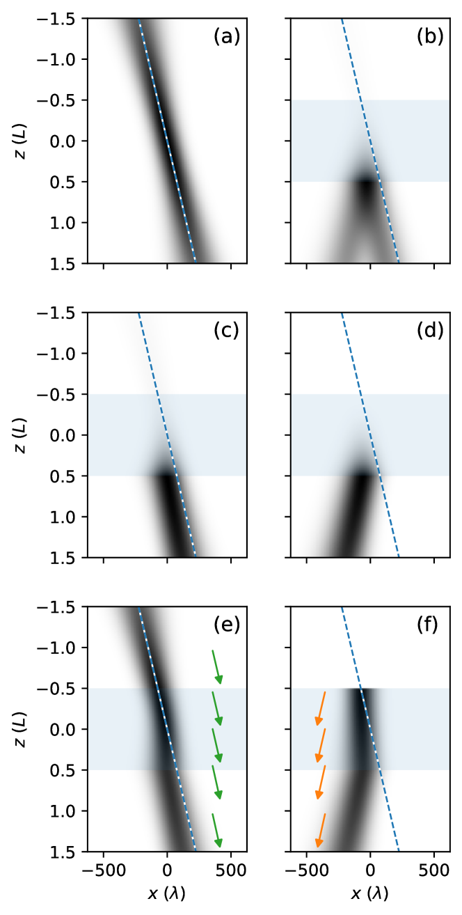
What happens inside the medium is more complex. Firstly, the width of the beams does not increase as much as one would expect in a naive model where mode 2 would appear as if born from every point on mode 1 trajectory, and reciprocally. This would result in modes 1 and 2 being overlapped at all , and having a width that increases linearly with .
Secondly, the apparent direction of propagation for both beams is different from the directions seen before (for mode 1) and after (for both modes 1 and 2) the medium. Mode 2 propagates along the direction, while mode 1 is drawn towards the direction, so that the distance between the two beams does not get larger than their size. As a result, mode 1 emerges from the medium at a position that is shifted with respect to free-space propagation, and mode 2 always emerges close to the seed (mode 1) position on the medium input interface. Fig.1 shows the effect for an amplification factor of mode 1 power of 30.
Note that light still propagates along the original direction at all times. Fig. 1(e, f) shows the average wave-vectors of modes 1 and 2 at various positions along the propagation. The directions of the wave-vectors remain constant, as long as the relative values of the seed average angle and the indices of refraction and are chosen so that the amplification is phase-matched. The effect of deflection is given by the fact that the beams are preferentially amplified in the region where they overlap, which keeps their transverse intensity (and field) center of mass in proximity. In terms of coupled modes emerging from the medium, the hitching effect is real and should have consequences on the structure of spatial squeezing and quantum correlations on the output of a thick OPA.
Although the coupled modes lock to each other when propagating, their positions when emerging from the medium do not coincide exactly. In Fig. 2, we show the apparent trajectory of the modes across the medium in the conditions of Fig. 1, as measured by the center of mass of their intensity profile. The plot shows that mode 2 is initially created at the position of mode 1. During propagation, the modes pull away from each other until the distance between them stabilizes as the gain on the seeded mode exceeds two. This is reminiscent of the propagation of matched pulses observed in an OPA [16], where coupled pulses with different group velocities get longitudinally hitched to each other. Here, the equivalent to the group velocity is the transverse velocity of the pulses, as measured by the position of their intensity center of mass or, alternatively, maximum intensity. In the geometry of our model, the transverse velocity of mode 2 remains roughly zero, while the transverse velocity of mode 1, initially equal to the free-space velocity, drops to zero to match the velocity of mode 2.
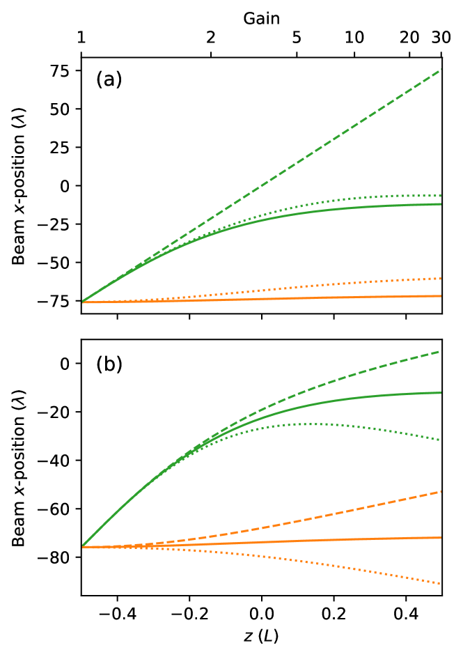
If we introduce loss (absorption) into one of the modes, the situation is modified as in Fig. 2(b). The separation between the modes becomes hitched quantitatively as in the lossless case, but the absolute positions of the modes tend towards the nominal propagation direction of the lossless mode. Note that the net gain at the output of the amplifier, as indicated in the figure, is reduced when there is loss. This means that for a given amplifier net gain, hitching will occur after a shorter propagation distance in the medium in the lossy case, compared to the lossless case.
Hitching is a two-beam effect. The trajectory of each of the beams is a function of the position of the other beam, and it is not necessarily a straight line. This is in contrast to refraction, which can deflect beams instantly at interfaces. This refraction, observed for a single beam in an atomic vapor subject to electromagnetically induced transparency and coherence diffusion, has been used to control diffraction [14]. In this case, the direction of propagation, dictated by loss rather than gain, does not depend on the longitudinal position inside the medium. The dynamics observed here is more related to predicted diffraction control using 4WM in an atomic vapor [15], in that the whole propagation through the medium must be considered to account for the position and size of twin beams at the output of the medium.
In the following sections, we implement an OPA based on 4-wave mixing in an atomic vapor that displays the generic hitching feature discussed above. In this setup, the length of the amplifier, , is fixed and cannot be varied. Instead, experimental conditions are altered to achieve a range of gains and losses. The transverse positions of mode 1 and mode 2 are measured after propagating by length to the output facet of the amplifier. At low gain and low loss, the modes are unhitched and mode 1 emerges at a position corresponding to free propagation throughout the amplifier. The generated mode, mode 2, stays in position. At high gain, the modes are hitched, and they emerge locked transversely closer to each other.
III Experimental setup
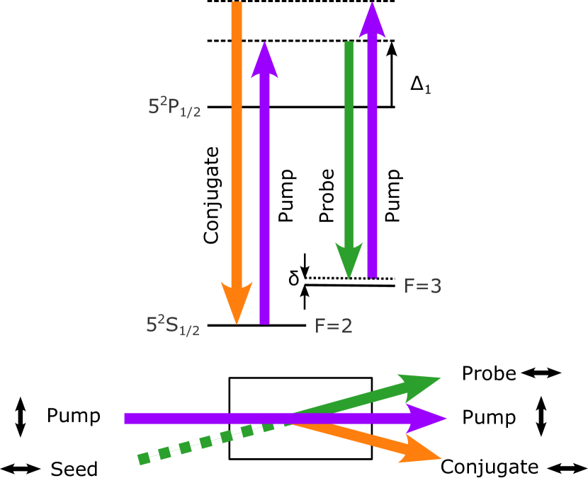
We implement a traveling-wave OPA using the so-called double-lambda scheme in a rubidium 85 vapor [17, 18]. A pump beam tuned to the blue of the D1 line is coupled to sidebands located at a plus and minus ground-state hyperfine splitting away from the pump frequency, as shown in Fig. 3. A probe beam, corresponding to mode 1 (the signal), intersects the pump beam at a small angle in a -long cell filled with a hot rubidium 85 vapor. The pump beam seeds the 4WM and is amplified while generating a beam in mode 2 (the idler), called here the conjugate. As the probe beam is closer to the atomic resonance, the probe beam sees an index of refraction slightly higher than that of the other beams, which is effectively 1 for them. Relating this to the theory section, this means that is negligible, whilst has a finite value. The latter is potentially complex if there is absorption on the probe beam. As a result, the process is phase matched for an angle of 4 to between each of the twin beams and the pump direction [9]. In these conditions, the process can exhibit a gain on the probe beam of up to 50 in a single pass. Moreover, the cross-coupling coefficient is mostly real [19], as considered in the model section.
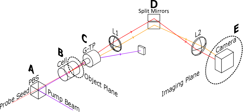
The relative position of the output beams is determined by imaging the output facet of the vapor cell on a CCD camera. Fig. 4 shows how the twin beams are imaged separately, so that their transverse positions can be resolved separately. Although we cannot measure the absolute or relative positions of the twin beams, we can measure changes in their positions. This is done by varying the system parameters that affect the gain and loss of the amplifier. One of these parameters is the pump intensity. In order to measure the effect of a range of intensities simultaneously, we position an elongated probe beam such that, in the amplifier, the probe beam extends from the center of the pump beam, where the intensity is maximum, up to the edge of the pump beam, where the intensity is near zero. The profiles of both beams are largely Gaussian. The geometry of the beams is shown in Fig. 5.
The vertical beam width of the probe in the gain medium is . It is larger than the coherence length but narrow enough to ensure that the pump intensity varies little across the probe in the vertical direction, which is also the direction in which the hitching occurs. The pump diameter is .
Images of the twin beams are captured both with the probe seed beam blocked and unblocked, so that remnant pump light can be measured and subtracted from the twin-beam images. The images are analyzed in amplitude and vertical position, as shown in Fig. 6. Statistical uncertainties on these measurements are evaluated across groups of five spatially adjacent values. These data are collected as system parameters, such as pump and probe frequencies, are varied to produce a range of values for coefficients and .
IV Results and discussion
At first, the atomic parameters, pump power and laser beam detunings, have been chosen to give pure gain and no loss on the probe and conjugate. The probe and conjugate positions measured at the output of the vapor cell, as functions of the net probe gain, are shown in Fig. 7. Gain variability is here only caused by the intensity profile of the pump.
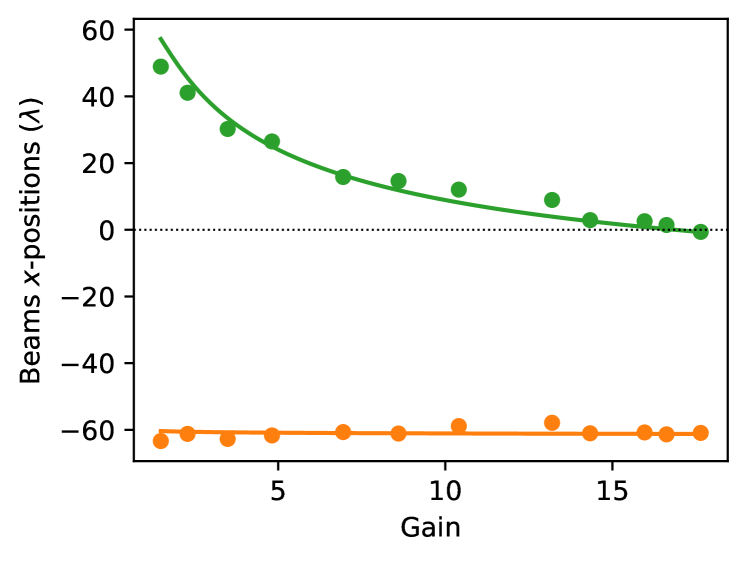
As expected for a lossless OPA, mode 2 (the conjugate) emerges in an almost constant position, regardless of gain. The situation is very different for mode 1 (the probe). At low gain, it emerges at the position that corresponds to free propagation, as indicated by the dashed line in Fig. 2(a). As the output gain increases, the point at which the probe start hitching to the conjugate, which is roughly when the intermediate gain reaches 2, as shown in that same figure, occurs earlier in the cell. This leads to a hitching distance that decreases as the output OPA gain increases.
The data in Fig. 7 are fitted using equations (4) and (5). As explained above, there is no direct coupling for the conjugate, therefore . Since there is no loss on the probe, the direct coupling is a real parameter, whose value is set so that the process is phase-matched at the experimentally determined angle of . The value of the cross-coupling coefficient is determined from the probe gain measured in each segment. The only free parameters are the vertical positions of the curves, since the optical setup does not allow us to make an absolute determination of the hitching distance. Under this restriction, the experimental results agree remarkably well with the theory curves, indicating that the main features of the hitching effect are captured.
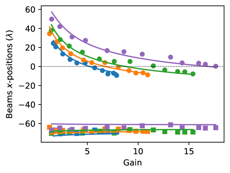
In a second experiment, we tune the optical parameters so that the probe experiences absorption in the atomic medium. This is achieved by reducing the detuning of the probe with the matching atomic transition, noted in Fig. 3. The smaller the detuning, the higher the absorption. Figure 8 shows the changes in the probe and conjugate exit positions for different values of the detuning. The data is fitted as previously done, but this time allowing the real part of the coefficient to vary as the detuning changes. It shows that at constant net gain, the distance between the twin beams decreases as the probe loss increases. This is consistent with the theoretical description given in section II. Loss causes earlier hitching in the medium, leading to a reduced hitching distance. The data also show that as the absorption in the probe increases, the propagation of the twin beams becomes biased toward the geometric conjugate propagation direction, as expected from the numerical results in Fig. 2(b).
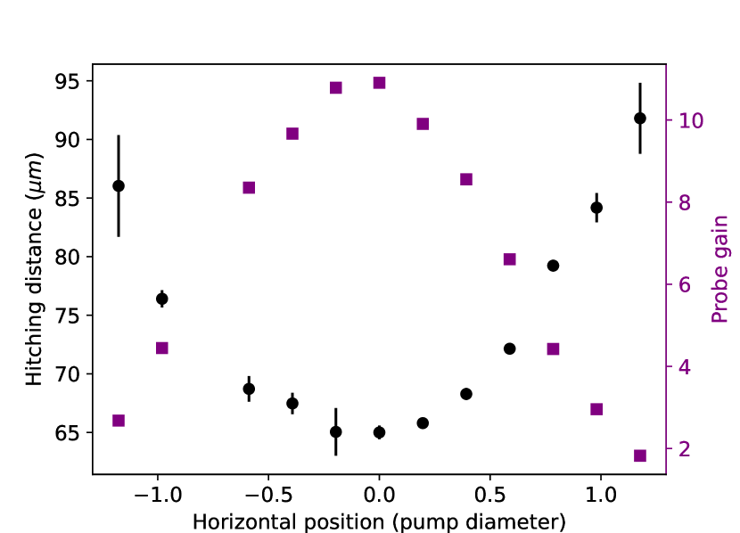
Finally, a single curve of the squeezing distance was produced as a function of the position inside the pump beam, for optical parameters that are optimum for squeezing or entanglement generation [20, 21, 22, 23, 24]. This is shown in Fig. 9. The distance between the beams is minimal at the center of the pump beam, where the pump intensity and the gain are maximal.
This observation is crucial for quantum imaging experiments using OPAs of finite lengths. A typical scenario would be to use quantum-correlated twin beams to perform absorption imaging on a faint object, one beam performing the probing and the other beam serving as an intensity reference [25]. Sub-shot-noise imaging is achieved by subtracting the reference from the probe. This can be done in the near field of the OPA, where the twin beams display spatially identical quantum fluctuations, or in the far field of the OPA, where the quantum fluctuations are symmetrical with respect to the propagation axis. In practice, the spatial correspondence between these fluctuations is affected by the fact that the pumping of the OPA is not spatially homogeneous because the pump beam has a finite width. When imaging in the far field, this can lead to cross-Kerr coupling with the pump and differentiated lensing of the twin beams [26]. When imaging in the near-field, inhomogeneous gain leads to spatially varying hitching, as described in this paper and shown in Fig. 9.
V Conclusion
We have presented a theoretical and experimental study of the propagation of twin beams (signal and idler) in a thick OPA. It shows that under a copropagation arrangement with a small angle between the input probe and a collimated pump (or generally a pumping mechanism that does not introduce phase modulation), the twin beams hitch to each other instead of pulling apart.
This effect is generic in parametric amplification and is distinct from the spatial walk-off observed in birefringent media. It is borne out of the trade-off between twin-beam production, which occurs where the beams overlap, and the phase-matching condition, which pulls the beams apart. This mechanism kicks in when the OPA gain exceeds 2. The final hitching distance between the beams decreases with the amplifier gain. When one of the twin beams is subject to absorption, the mean final position of the combined beams depends on the relative optical power between them, with the brighter one having the largest influence on their common direction of propagation.
We expect this effect, shown here classically, to persist in the quantum regime. We have shown that differential hitching due to inhomogeneous pumping is prevalent in the parameter range where large quantum squeezing is normally observed. This raises the possibility of directly observing the resulting disturbance in the spatial mapping between the local quantum fluctuations of the twin beams. It also suggests that some form of spatial correction, optical or digital, needs to be applied in quantum noise subtraction when doing quantum imaging near field of the OPA.
References
- Slusher et al. [1985] R. E. Slusher, L. W. Hollberg, B. Yurke, J. C. Mertz, and J. F. Valley, Observation of Squeezed States Generated by Four-Wave Mixing in an Optical Cavity, Phys. Rev. Lett. 55, 2409 (1985).
- Wu et al. [1986] L.-A. Wu, H. J. Kimble, J. L. Hall, and H. Wu, Generation of Squeezed States by Parametric Down Conversion, Phys. Rev. Lett. 57, 2520 (1986), publisher: American Physical Society.
- Kwiat et al. [1995] P. G. Kwiat, K. Mattle, H. Weinfurter, A. Zeilinger, A. V. Sergienko, and Y. Shih, New High-Intensity Source of Polarization-Entangled Photon Pairs, Phys. Rev. Lett. 75, 4337 (1995), publisher: American Physical Society.
- Howell et al. [2004] J. C. Howell, R. S. Bennink, S. J. Bentley, and R. W. Boyd, Realization of the Einstein-Podolsky-Rosen Paradox Using Momentum- and Position-Entangled Photons from Spontaneous Parametric Down Conversion, Phys. Rev. Lett. 92, 210403 (2004), publisher: American Physical Society.
- Ou et al. [1992] Z. Y. Ou, S. F. Pereira, H. J. Kimble, and K. C. Peng, Realization of the Einstein-Podolsky-Rosen paradox for continuous variables, Phys. Rev. Lett. 68, 3663 (1992).
- Heidmann et al. [1987] A. Heidmann, R. J. Horowicz, S. Reynaud, E. Giacobino, C. Fabre, and G. Camy, Observation of Quantum Noise Reduction on Twin Laser Beams, Phys. Rev. Lett. 59, 2555 (1987), publisher: American Physical Society.
- Kumar and Kolobov [1994] P. Kumar and M. I. Kolobov, Degenerate four-wave mixing as a source for spatially-broadband squeezed light, Optics Communications 104, 374 (1994).
- Brambilla et al. [2008] E. Brambilla, L. Caspani, O. Jedrkiewicz, L. A. Lugiato, and A. Gatti, High-sensitivity imaging with multi-mode twin beams, Phys. Rev. A 77, 053807 (2008), publisher: American Physical Society.
- Boyer et al. [2008] V. Boyer, A. M. Marino, and P. D. Lett, Generation of Spatially Broadband Twin Beams for Quantum Imaging, Phys. Rev. Lett. 100, 143601 (2008).
- Corzo et al. [2011] N. Corzo, A. M. Marino, K. M. Jones, and P. D. Lett, Multi-spatial-mode single-beam quadrature squeezed states of light from four-wave mixing in hot rubidium vapor, Opt. Express 19, 21358 (2011).
- Brambilla et al. [2004] E. Brambilla, A. Gatti, M. Bache, and L. A. Lugiato, Simultaneous near-field and far-field spatial quantum correlations in the high-gain regime of parametric down-conversion, Phys. Rev. A 69, 023802 (2004), publisher: American Physical Society.
- Lopez et al. [2005] L. Lopez, S. Gigan, N. Treps, A. Maître, C. Fabre, and A. Gatti, Multimode squeezing properties of a confocal optical parametric oscillator: Beyond the thin-crystal approximation, Phys. Rev. A 72, 013806 (2005).
- Slusher et al. [1987] R. E. Slusher, P. Grangier, A. LaPorta, B. Yurke, and M. J. Potasek, Pulsed Squeezed Light, Phys. Rev. Lett. 59, 2566 (1987), publisher: American Physical Society.
- Firstenberg et al. [2009] O. Firstenberg, P. London, M. Shuker, A. Ron, and N. Davidson, Elimination, reversal and directional bias of optical diffraction, Nature Physics 5, 665 (2009).
- Katzir et al. [2015] I. Katzir, A. Ron, and O. Firstenberg, Diffraction manipulation by four-wave mixing, Optics Express 23, 6379 (2015).
- Boyer et al. [2007] V. Boyer, C. F. McCormick, E. Arimondo, and P. D. Lett, Ultraslow Propagation of Matched Pulses by Four-Wave Mixing in an Atomic Vapor, Phys. Rev. Lett. 99, 143601 (2007).
- McCormick et al. [2007] C. F. McCormick, V. Boyer, E. Arimondo, and P. D. Lett, Strong relative intensity squeezing by four-wave mixing in rubidium vapor, Opt. Lett. 32, 178 (2007).
- Wei et al. [2015] D. Wei, J. Liu, Y. Yu, J. Wang, H. Gao, and F. Li, Generation of twin Airy beams with a parametric amplifier, J. Phys. B: At. Mol. Opt. Phys. 48, 245401 (2015), publisher: IOP Publishing.
- Turnbull et al. [2013] M. T. Turnbull, P. G. Petrov, C. S. Embrey, A. M. Marino, and V. Boyer, Role of the phase-matching condition in nondegenerate four-wave mixing in hot vapors for the generation of squeezed states of light, Phys. Rev. A 88, 033845 (2013).
- McCormick et al. [2008] C. F. McCormick, A. M. Marino, V. Boyer, and P. D. Lett, Strong low-frequency quantum correlations from a four-wave-mixing amplifier, Phys. Rev. A 78, 043816 (2008).
- Glorieux et al. [2011] Q. Glorieux, L. Guidoni, S. Guibal, J.-P. Likforman, and T. Coudreau, Quantum correlations by four-wave mixing in an atomic vapor in a nonamplifying regime: Quantum beam splitter for photons, Phys. Rev. A 84, 053826 (2011), publisher: American Physical Society.
- Qin et al. [2012] Z. Qin, J. Jing, J. Zhou, C. Liu, R. C. Pooser, Z. Zhou, and W. Zhang, Compact diode-laser-pumped quantum light source based on four-wave mixing in hot rubidium vapor, Opt. Lett., OL 37, 3141 (2012), publisher: Optica Publishing Group.
- Qin et al. [2014] Z. Qin, L. Cao, H. Wang, A. Marino, W. Zhang, and J. Jing, Experimental Generation of Multiple Quantum Correlated Beams from Hot Rubidium Vapor, Phys. Rev. Lett. 113, 023602 (2014), publisher: American Physical Society.
- Ma et al. [2018] R. Ma, W. Liu, Z. Qin, X. Su, X. Jia, J. Zhang, and J. Gao, Compact sub-kilohertz low-frequency quantum light source based on four-wave mixing in cesium vapor, Opt. Lett., OL 43, 1243 (2018), publisher: Optica Publishing Group.
- Brida et al. [2010] G. Brida, M. Genovese, and I. R. Berchera, Experimental realization of sub-shot-noise quantum imaging, Nat Photon 4, 227 (2010).
- Kumar et al. [2017] A. Kumar, H. Nunley, and A. M. Marino, Observation of spatial quantum correlations in the macroscopic regime, Phys. Rev. A 95, 053849 (2017), publisher: American Physical Society.