Fast quantum gates for exchange-only qubits using simultaneous exchange pulses
Abstract
The benefit of exchange-only qubits compared to other spin qubit types is the universal control using only voltage controlled exchange interactions between neighboring spins. As a compromise, qubit operations have to be constructed from non-orthogonal rotation axes of the Bloch sphere and result in rather long pulsing sequences. This paper aims to develop a faster implementation of single-qubit and two-qubit gates using simultaneous exchange pulses. We introduce pulse sequences in which single-qubit gates could be executed faster and show that subsequences on three spins in two-qubit gates could be implemented in fewer steps. Our findings can particularly speed up gate sequences for realistic idle times between sequential pulses and we show that this advantage increases with more interconnectivity of the quantum dots. We further demonstrate how a phase operation can introduce a relative phase between the computational and some of the leakage states, which can be advantageous for the construction of two-qubit gates. In addition to our theoretical analysis, we experimentally demonstrate and characterize a simultaneous exchange implementation of rotations in a SiGe quantum dot device and compare to the state of the art with sequential exchange pulses.
I Introduction
In recent years there has been immense progress in spin qubit devices in Si/SiGe heterostructures reaching up to six qubits in a quantum processor [1] using Loss-DiVincenzo (LD) qubits [2]. LD qubits are formed by trapping a single electron or hole in a gate-defined quantum dot to use the spin degree as computational unit, the qubit. However, when scaling up LD qubits the delivery of high-power oscillating signals required for qubit rotations causes heating and wiring issues leading to fidelity limitations [3, 4, 5, 6]. Thus it is reasonable to investigate qubit types using different operation schemes. In contrast to LD qubits exchange-only (EO) qubits [7] only require one type of interaction, namely the exchange between neighboring spins to realize universal qubit control. Hence, EO qubits utilize baseband pulses and do not need high-power ac fields. Moreover, for EO qubits a magnetic field gradient is not required, which represents an advantage regarding scalability. In fact, inhomogeneities of the magnetic field can cause dephasing and leakage in EO qubits [8].
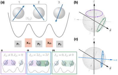
In the EO architecture, each qubit is represented by the spins of three electrons hosted in three adjacent quantum dots (Fig. 1(a)), and quantum gates are generated by pulsing exchange interactions between electrons. Out of the resulting eight-dimensional Hilbert space, four states are computational states and four are leakage states. Single-qubit gates involve exchange interactions between the electrons belonging to the same qubit and are usually composed of up to four rotations around two different axes [7, 9] (Fig. 1(b)). Two-qubit gates require exchange interactions between electrons from different qubits. Non-trivial pulse sequences of several exchange pulses populating and depopulating leakage states result in gates such as the CNOT, CZ or SWAP gate [7, 10, 11, 12, 13]. With few exceptions, the sequences that are found to result in two-qubit gates, however, assume only commuting exchange pulses to be pulsed at a time. Here we investigate simultaneous application of non-commuting exchange-pulses to obtain quantum gates with fewer pulses, and hence faster executions of gate sequences. We derive conditions on the exchange signals and compare the results to sequential gate operations.
This paper is organized as follows. We introduce the exchange-only qubit in Sec. II and theoretically show how single-qubit gates can be implemented using fewer pulses in Sec. II.1. We experimentally demonstrate the concept of simultaneous exchange pulses in Sec. II.2. We show how a simultaneous gate can perform a direct rotation by tuning the gate voltages into the appropriate regime and discuss the relative effect of charge noise in comparison to the sequential counterpart. In Sec. II.3 we investigate two-qubit gate subsequences and present an operation introducing phases between qubit states and selected leakage states. We extend our description from a linear to an all-to-all connectivity in Sec. II.4 and summarize the results for frequently used quantum gates in Tables 1 and 2.
II Results
To describe exchange-only (EO) qubits in this work we restrict a quantum dot array to be in the (1,1,…) charging regime with one electron in each dot, in which each electron is well described by its spin, and pairwise interactions follow the Heisenberg Hamiltonian
| (1) |
where describes the exchange interaction between spin and . In Appendix A we derive the exchange interaction from the Hubbard model and show the optimal operation point to be less sensitive to charge noise. An optional global magnetic field can increase the coherence time making transverse fluctuations of the local magnetic field negligible. Global field fluctuations do not have any impact on an EO qubit, since the corresponding operator commutes with the Hamiltonian. In the following we will label the spins (as in Fig. 1) by numbers from left to right, where only nearest neighbors are connected via exchange interaction.
In the absence of an external magnetic field, and when , the EO qubit is in its idle state and all eight energy states are degenerate. Pulsing the exchange interaction causes two of the energy levels to lower and thus pick up a phase relative to the other states. In fact, any operations on one or more qubits are entirely performed by only pulsing the exchange interaction between spins, which will result in a rotation of a subspace of the full Hilbert space.
II.1 Single-qubit gates
Instead of the standard spin-up and spin-down basis, the Clebsch-Gordan coefficients are used to transform the single-qubit Hamiltonian to a basis using total spin , its projection , and the combined spin on sites 1 and 2, . We then express the Hamiltonian in terms of the basis states ,
| (2) | ||||||
Here , , , are the computational basis states with total spin 1/2 and spin projection down and up, respectively, and , , , correspond to the four leakage states with total spin 3/2.
We consider the qubit space for the decoherence-free subsystem with total spin 1/2, i.e., we do not favor one of the two possible spin polarizations. Since exchange coupling preserves the total spin, the Hamiltonian can be effectively written in the basis as
| (3) |
omitting the inconsequential term proportional to the identity. Both blocks are entirely decoupled from the leakage states in the absence of local magnetic noise.
Different from single-spin qubits, EO single-qubit gates need to be constructed from rotations around two non-orthogonal axes, the axis and the vector (Fig. 1(b)), using 1 up to 4 pulses [7, 9]. A rotation around the axis is accomplished by only switching on (). The time evolution is then given by where is the rotation angle. Similarly if turning on only exchange (), the time evolution with results in a rotation around the vector (green circle in Fig. 1(b). The and gates can be composed by the sequences and with and , respectively [9].
In general, any rotation axis in the - plane enclosed by the axis and is possible. Thus a direct rotation around the axis in the opposite rotational direction (Fig. 1(c)) can be realized using a simultaneous (or parallel [7]) pulsing of both exchange values with , as the terms cancel in the Hamiltonian in Eq. (3). The time evolution is then given by
| (4) |
with rotation angle . Note that in this case the Hamiltonian commutes for all times (i.e. for arbitrary ). When assuming rectangular pulses with maximal experimentally achievable exchange the gate time of the sequential gate is then , while for the simultaneous gate the gate time is , where is the idle time after each pulse [14]. Consequently, the simultaneous gate is faster compared to its sequential counterpart, by a factor between 1.39 and 3 for realistic pulse times detailed in Table 1.
These findings indicate that more frequently used single-qubit gates may benefit from the simultaneous pulsing of exchange couplings. Indeed, we find that the , and gates, where and is the Hadamard gate, can be implemented using one simultaneous pulse step instead of three sequential ones. Furthermore, most gates in Table 1 can be implemented using two pulses instead of three, which results in a decrease of the average gate time by .
II.2 Experiment and simulation
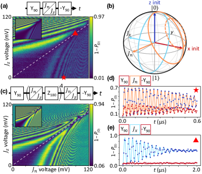
To verify and characterize the operation of simultaneous exchange, a SiGe quantum dot device fabricated by Intel [15] is tuned up as an exchange-only qubit [16]. The qubit is encoded across three quantum dots underneath metal “plunger” gates with “barrier” gates in between dots to control the exchange. The qubit is controlled via baseband pulses on the barrier gates and readout is performed using Pauli spin blockade with signal amplified by SiGe heterojunction bipolar transistor (HBT) cryogenic amplifiers [17].
To reduce sensitivity to charge noise and calibrate exchange, “fingerprint” plots [18] are acquired for the “” and “” control axes, corresponding to and , respectively, where points down 120 degrees from the -axis, analogous to Fig. 1(b). For that the exchange interaction is varied as a function of barrier voltage and detuning, leading to the typical appearance of a fingerprint. In fact, for a fixed time of 100 ns, the barrier gate bias is pulsed to larger values while the voltage detuning between two surrounding plunger gates is pulsed from negative to positive values. fingerprint plots can be taken after preparing a singlet state, but fingerprints must have a pre- and post- rotation applied which brings the state to and from the plane of the Bloch sphere, respectively.
A typical fingerprint plot uses two plungers and one barrier to increase only one exchange term and calibrate one rotation axis, which can then be used for serial exchange control. To increase both exchange terms simultaneously, the two barrier gates are pulsed together for a fixed time, and is plotted in the “fingerpinch” plot in Figure 2(a), where is the probability of measuring the ground state . The Pauli spin blockade readout only detects whether the two neighboring spins 1 and 2 in Fig. 1(a) are in a singlet state or not, entirely neglecting the spin projection . If a singlet state is prepared, it will only be rotated by the exchange, therefore, we prepare an eigenstate using a - prerotation, which uses alternating and exchange pulses. The eigenstate can be rotated by either (lower right region of plot) or (upper left region). Additionally, the eigenstate will not be rotated when the total exchange points along the -axis, therefore the darker, linear region of the upper right defines the “” regime and is indicated with a white dashed line. Theoretical calculations of the expected rotation outcomes are plotted in the upper left and agree well with the data.
A modified fingerpinch plot is acquired and plotted in Figure 2(c), where alternating - gates and exchange pulses are applied to echo the state and extend the rotation visibility, particularly in the regime (lower right region of plot). Here, the axis highlighted by the white dashed line is more visible throughout the plot with theoretical predictions again in agreement. Figure 2(d) shows time-domain data for rotations, where the barrier is pulsed to a fixed value shown by the red star in figure 2(a). Either a singlet state (blue data points) or an eigenstate (red points) is prepared as depicted as a blue and red initial state on the Bloch sphere in Fig. 2(b). The frequency of the rotations is MHz with a quality factor of . Similarly, Figure 2(e) shows the time-domain data, taken with barriers pulsed to the upper right region of the fingerpinch plot (red triangle point in Figure 2(a)). The frequency is MHz and the quality factor is a lower value . As expected, does not rotate an eigenstate (red points). The rotations corresponding to and are shown in Fig. 2(b) in orange and light blue, respectively.
The lower quality factor of the rotations may be due to multiple effects. Since the system now forms two charge dipoles instead of one, any charge noise present in the immediate area may couple in to a greater degree. Additional optimizations to tune into a “sweet spot” to minimize charge noise may be possible. Follow-up experiments include pulsing the detuning axis of the two outer plungers as the two barrier gates are pulsed to greater values with different offsets.
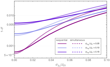
Charge noise enters in the Hamiltonian (1) as fluctuations in the exchange interaction. A simple estimation for the fidelity is to assume quasi-static exchange fluctuations on each exchange value separately. In Fig. 3 we compare the sequential (solid lines) and simultaneous (dashed lines) gate with linear connectivity for various , where is the standard deviation. We find that both, the sequential and the simultaneous pulse gate fidelities have a similar behaviour with a stronger dependence on the fluctuations in than in . For the sequential gate this can be explained by the larger overall rotation angle around induced by in the gate construction, whereas for the simultaneous gate it is due to the fact that . Any deviation from this ratio results in a tilt of the rotation axis and can result in an additional over- or underrotation. For larger we find a slightly better performance for the sequential gate, however, for biased noise in the different exchange interactions with, e.g., % and %, we even find a fidelity improvement when using the simultaneous pulses.
II.3 Two-qubit gate subsequences
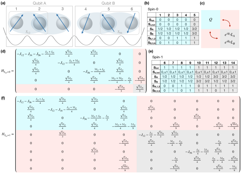
To construct two-qubit gates for qubits denoted and , it is advantageous to use the total spin basis of the entire six spin system . Since and are preserved under exchange interactions, blocks with different total spins are separable as they do not couple to each other [7, 10]. As shown in Fig. 6(a) we label the chain of six spins from left to right with numbers and assume the outer two spins of each triple to be initialized in a singlet configuration as described in Ref. [14]. We label the left three spins as qubit and the right three spins as qubit . For this configuration we list the possible basis states in the total spin basis of the and 1 subspace in Fig. 6(b) and (e), respectively. Each qubit, and , is operated in the single-qubit spin subspace, thus only the total spin subspaces and cover the computational space. For each block the Hamiltonian is schematically shown in Fig. 6(c). The computational subspace is colored in light blue and the leakage states in gray. The Hamiltonian in Eq. (1) can be written in the blocks as shown in Fig. 6(d) and 6(f), respectively.
In this basis one can construct sub-sequences containing rotations in subspaces of the full Hilbert space as in Refs. [11, 12, 19] or apply e.g. genetic algorithms to search for a pulse sequence overall resulting in
| (5) |
Here corresponds to the unitary describing the two-qubit gate operation in the subspace spanned by the first four basis states (1-4 and 6-9 respectively) neglecting , whereas can be an arbitrary unitary acting only within the non-computational leakage states (basis states 5 and 10-14, respectively). For subspaces and the unitaries and can be arbitrary in general. Although the leakage states lie outside the computational space, it is necessary to take them into account when constructing gate sequences; also, the leakage states can be beneficial for reducing leakage errors. Examples for leakage-controlled CZ (LCCZ) and CNOT (LC-CNOT) gates are given in Ref. [14].
Since we are seeking shorter gate sequences, we investigate combinations of subsequences in some of the relevant two-qubit gates such as CZ, CNOT and SWAP. A trivial but useful fact in larger sequences is that if the first and third rotation are by an angle of , , the rotation sequence can be mirrored, i.e. . As the -rotations swap the spins in such a way, that the outer spins interact with each other and then bring them back into the initial order, it does not matter which spins, i.e. 1 and 2 or 2 and 3, are swapped to achieve this. In general, non-adjacent exchange interactions can be pulsed at the same time as their Hamiltonians commute. While two subsequent adjacent exchange pulses cannot be replaced by a single pulse, three exchange pulses on three spins can be compressed in this way if the resulting rotation within the respective subspace is around a feasible axis (i.e., any axis between the z axis and ). Therefore, we focus on subsequences that are performed on three spins. Note that if these spins belong to the same qubit these ultimately are single-qubit gates within a larger sequence. Furthermore, a necessary but not sufficient condition for replacing a pulse sequence with three pulses (two alternating exchange interaction pulses or ) is that the first and third rotation angles are the same, i.e. .
In the following we discuss the construction of simultaneous gates to replace three-pulse sequences in two qubit gates. For that we (i) identify suitable subsequences, (ii) describe the construction only in a single-qubit computational subspace to find the respective gate, and (iii) correct for any relative phase to the leakage space.
From several sequences in Ref. [14] we first extract those three-pulse combinations, for which first and third rotation angles are equal and for which we can find alternative simultaneous pulses if they were applied only on a single qubit. The original sequence is shown in the first column of Table 2. For all of these sequences we can find a simultaneous exchange pulse, fulfilling the given conditions, such that the computational space unitary equals the 3-pulse sequence (shown in the left half of the second column). For actual single-qubit gates this is sufficient. However, since during two-qubit gates the purposeful population and depopulation of leakage states is crucial, the relative phases between the total basis states 1-14 in Fig. 6(b) and Fig. 6(e) are of importance. We observe that during simultaneous pulsing of the exchange values, the relative phase (given in the third column in Tab. 2) between some of the states changes compared to the 3-pulse sequence. For instance, if the simultaneous pulse is executed on qubit , in the block the states 1-4 in Fig. 6(b) acquire a relative phase and in the block states 6-11 in Fig. 6(e) acquire the same relative phase, while states 5 and 12-14 do not. Thus, to obtain the exact same gate sequence one has to account for this phase in a second pulse. We add a subsequent simultaneous exchange pulse with and diagonalize the time evolution by choosing a pulse duration to obtain unitaries that cancel out relative phases between the respective computational and leakage states
| (6) | ||||
| (7) |
where . Analogously, if qubit is operated, i.e. , we obtain
| (8) | ||||
| (9) |
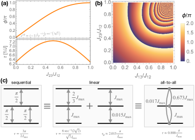
with and . We note that as long as the Hamiltonians of qubit and commute and thus both operations can be pulsed simultaneously, if necessary. From the expressions for and we can obtain the possible correction angles in a single drive which lie between and as depicted in the upper plot in Fig. 4(a) for a varying ratio of . The lower plot shows the corresponding pulse time. Consequently, we find a two-step simultaneous exchange pulse sequence to replace a three-step single pulse sequence, in case the correction phase lies in the respective phase range. As an example in Fig. 4(c) the sequence is shown, which can be replaced by two simultaneous pulses. The total pulse time for the simultaneous case exceeds the total pulse time of the sequential counterpart, . Nevertheless, due to finite fall times of the barrier voltages, an idle time is usually required. For the sequential gate this yields a total gate time while for the simultaneous pulses the total gate time is . Ultimately, for a long idle time , the simultaneous pulsing becomes beneficial compared to the sequential state of the art. Furthermore, by taking into account the correction phase in a second pulse, the three-pulse sequences in Tab. 2 of any neighboring exchange pair can be replaced. However, when replacing the three-step sequences by the two-step simultaneous pulses in, e.g., the Fong-Wandzura CZ gate sequence, we do not find an overall time improvement, since the circuit was designed and optimized for the brick structure, where only commuting exchange interactions are allowed to be driven simultaneously. Instead, our result shows that there is room for improvement of the currently shortest sequences, an insight that may trigger the exploration of new two-qubit pulse sequences optimized for simultaneous pulsing.
II.4 All-to-all connectivity
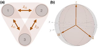
Although, for the most part, exchange-only qubits were demonstrated in 1D qubit chains, we point out that in future 2D layouts, the connectivity of exchange-only qubits might vary [20]. Indeed, recently a triangular exchange-only spin qubit was demonstrated [21]. Additionally, the simultaneous pulsing of exchange interactions could give rise to a super-exchange and many-body interactions between next-nearest neighbors [22, 23]. Thus, we consider the Hamiltonian in Eq. (1) with three spins and all-to-all connection (, and ) as depicted in Fig. 5(a). Again, we can separate the Hamiltonian in the basis of into
| (10) |
and a term proportional to the identity, leading to a phase of between qubit and leakage space. Similar to the linear connectivity case the insensitivity to voltage fluctuations in the dot potential [24, 25] can be derived from a Hubbard model as shown in the Appendix A.
In case all interactions are independently tunable, the previously discussed pulsing schemes still apply. Furthermore, all rotation axes lying in the plane are possible in a single simultaneous pulse, as depicted in Fig. 5(b). The two vectors and correspond to and , respectively. In particular a single-pulse implementation of a rotation around the -axis requires . We find a rotation around the vector for and around the vector for . Thus rotations around an angle can be realized fastest with and around can be realized fastest with . Moreover, a frequently used gate in quantum algorithms, the Hadamard gate, can be realized using one simultaneous pulse with a gate time comparable to the and gate. We summarize and compare simultaneous single-qubit gates to sequential pulses and linearly connected qubit architectures in Tab. 1. We point out that whereas excluding the identity the average gate time for sequential pulses is 73.420 ns, for simultaneous pulses in linearly connected quantum dots it is 60.010 ns, while for all-to-all connectivity it reduces to 44.136 ns. Here we assumed rectangular exchange pulses with maximal exchange value MHz each. As the gate time reduces with simultaneous pulsing the number of applied quantum gates can be increased until the qubit loses its coherence.
Analogously to the linear case, we again consider the subsequences in two-qubit gates given in Tab. 2 and find single-pulse implementations. Since all-to-all connectivity gives an additional degree of freedom it is possible to compensate for phases within one pulse. In Fig. 4(c) the single-pulse gate with all-to-all connectivity equivalent to a sequence is showcased.
Furthermore, not only can these selected subsequences be achieved when using simultaneous pulsing with all-to-all connected spins, but we can also engineer the relative phase between qubit and leakage states by diagonalizing the time evolution using . Then we obtain a time evolution as in Eqs. (6) and (7) where the phase can assume any possible value . In Fig. 4(b) is calculated depending on the ratios and .
III Conclusions
In this paper we have shown an alternative pulsing scheme to operate exchange-only qubits using two neighboring exchange pulses simultaneously. We have found conditions for faster single-qubit gates with fewer pulses and compared the linear and all-to-all connected arrangement, and found that the latter offers more flexibility and thus even faster gates.
By investigating reoccurring subroutines in two-qubit sequences, we provide gate implementations in fewer steps and propose to search for a construction of two-qubit gates using subroutines of simultaneous exchange pulses. We further show that with simultaneous pulses we can introduce relative phases between qubit and various leakage states, which can also be used as subroutines when constructing two-qubit gates sequences. We expect this construction to become advantageous for two-qubit gates and possibly even for error mitigation schemes to account for leakage errors.
We also prove the concept with an experimental realization of a direct gate using simultaneous pulses and characterize the operation regime for the two exchange interactions. Although we believe the experiment is limited by charge noise, we theoretically predict a charge noise regime in which the simultaneous gate performs better than the state-of-the-art construction utilizing three single exchange pulses. In addition to the presence of noise and decoherence in exchange-only qubits, some remaining issues with our proposed scheme are the precise calibration and voltage control in the device, which needs to be improved in future experiments. We conclude that our proposed concept for the pulse construction with simultaneous exchange interactions offers a great potential to reduce the number of pulses for faster quantum gates in exchange-only qubits being compatible with other qubit implementations.
![[Uncaptioned image]](/html/2409.05843/assets/x6.png)
![[Uncaptioned image]](/html/2409.05843/assets/x8.png)
Acknowledgments
This work has been supported by QLSI with funding from the European Union’s Horizon 2020 research and innovation programme under grant agreement No. 951852.
Author contributions
The theoretical analysis was performed by I.H. R.K. helped writing the simulation code. F.A.M provided pulse sequence timing information and the energy scales. F.B., M.C., and M.T.M. developed the measurement routine and performed the experiment. F.L. built the measurement software framework. N.B. coordinated the project and edited the draft and figures. G.B. supervised the project and helped writing the manuscript.
Appendix A Charge noise sweet spots in triple quantum dots
For triple quantum dots a charge noise sweet spot was shown for the linear connectivity [24, 25]. Analogously, a sweet spot for the all-to-all connectivity is obtained. Using the Hubbard model,
| (11) |
where and we obtain the exchange interactions between neighboring electron spins
| (12) | |||
| (13) | |||
| (14) |
Here we defined , and . We find a first order sweet spot for fluctuations in if
| (15) | |||
| (16) |
References
- Philips et al. [2022] S. G. J. Philips, M. T. Mądzik, S. V. Amitonov, S. L. de Snoo, M. Russ, N. Kalhor, C. Volk, W. I. L. Lawrie, D. Brousse, L. Tryputen, B. P. Wuetz, A. Sammak, M. Veldhorst, G. Scappucci, and L. M. K. Vandersypen, Universal control of a six-qubit quantum processor in silicon, Nature 609, 919 (2022).
- Loss and DiVincenzo [1998] D. Loss and D. P. DiVincenzo, Quantum computation with quantum dots, Phys. Rev. A 57, 120 (1998).
- Undseth et al. [2023a] B. Undseth, X. Xue, M. Mehmandoost, M. Rimbach-Russ, P. T. Eendebak, N. Samkharadze, A. Sammak, V. V. Dobrovitski, G. Scappucci, and L. M. Vandersypen, Nonlinear response and crosstalk of electrically driven silicon spin qubits, Phys. Rev. Appl. 19, 044078 (2023a).
- John et al. [2024] V. John, F. Borsoi, Z. György, C.-A. Wang, G. Széchenyi, F. van Riggelen-Doelman, W. I. L. Lawrie, N. W. Hendrickx, A. Sammak, G. Scappucci, A. Pályi, and M. Veldhorst, Bichromatic rabi control of semiconductor qubits, Phys. Rev. Lett. 132, 067001 (2024).
- Kelly et al. [2023] E. G. Kelly, A. Orekhov, N. Hendrickx, M. Mergenthaler, F. Schupp, S. Paredes, R. S. Eggli, A. V. Kuhlmann, P. Harvey-Collard, A. Fuhrer, and G. Salis, Capacitive crosstalk in gate-based dispersive sensing of spin qubits (2023), arXiv:2309.10473 [cond-mat.mes-hall] .
- Undseth et al. [2023b] B. Undseth, O. Pietx-Casas, E. Raymenants, M. Mehmandoost, M. T. Mądzik, S. G. J. Philips, S. L. de Snoo, D. J. Michalak, S. V. Amitonov, L. Tryputen, B. P. Wuetz, V. Fezzi, D. D. Esposti, A. Sammak, G. Scappucci, and L. M. K. Vandersypen, Hotter is easier: Unexpected temperature dependence of spin qubit frequencies, Phys. Rev. X 13, 041015 (2023b).
- DiVincenzo et al. [2000] D. P. DiVincenzo, D. Bacon, J. Kempe, G. Burkard, and K. B. Whaley, Universal quantum computation with the exchange interaction, Nature 408, 339 (2000).
- Kerckhoff et al. [2021] J. Kerckhoff, B. Sun, B. Fong, C. Jones, A. Kiselev, D. Barnes, R. Noah, E. Acuna, M. Akmal, S. Ha, J. Wright, B. Thomas, C. Jackson, L. Edge, K. Eng, R. Ross, and T. Ladd, Magnetic gradient fluctuations from quadrupolar in / exchange-only qubits, PRX Quantum 2, 010347 (2021).
- Andrews et al. [2019] R. W. Andrews, C. Jones, M. D. Reed, A. M. Jones, S. D. Ha, M. P. Jura, J. Kerckhoff, M. Levendorf, S. Meenehan, S. T. Merkel, A. Smith, B. Sun, A. J. Weinstein, M. T. Rakher, T. D. Ladd, and M. G. Borselli, Quantifying error and leakage in an encoded si/sige triple-dot qubit, Nat. Nanotechnol. 14, 747–750 (2019).
- Fong and Wandzura [2011] B. H. Fong and S. M. Wandzura, Universal quantum computation and leakage reduction in the 3-qubit decoherence free subsystem (2011), arXiv:1102.2909 [quant-ph] .
- Zeuch et al. [2014] D. Zeuch, R. Cipri, and N. E. Bonesteel, Analytic pulse-sequence construction for exchange-only quantum computation, Phys. Rev. B 90, 045306 (2014).
- Zeuch and Bonesteel [2016] D. Zeuch and N. E. Bonesteel, Simple derivation of the fong-wandzura pulse sequence, Phys. Rev. A 93, 010303 (2016).
- Ivanova-Rohling et al. [2024] V. N. Ivanova-Rohling, N. Rohling, and G. Burkard, Discovery of an exchange-only gate sequence for cnot with record-low gate time using reinforcement learning (2024), arXiv:2402.10559 [quant-ph] .
- Weinstein et al. [2023] A. J. Weinstein, M. D. Reed, A. M. Jones, R. W. Andrews, D. Barnes, J. Z. Blumoff, L. E. Euliss, K. Eng, B. H. Fong, S. D. Ha, D. R. Hulbert, C. A. C. Jackson, M. Jura, T. E. Keating, J. Kerckhoff, A. A. Kiselev, J. Matten, G. Sabbir, A. Smith, J. Wright, M. T. Rakher, T. D. Ladd, and M. G. Borselli, Universal logic with encoded spin qubits in silicon, Nature 615, 817–822 (2023).
- Neyens et al. [2024] S. Neyens, O. K. Zietz, T. F. Watson, F. Luthi, A. Nethwewala, H. C. George, E. Henry, M. Islam, A. J. Wagner, F. Borjans, E. J. Connors, J. Corrigan, M. J. Curry, D. Keith, R. Kotlyar, L. F. Lampert, M. T. Mądzik, K. Millard, F. A. Mohiyaddin, S. Pellerano, R. Pillarisetty, M. Ramsey, R. Savytskyy, S. Schaal, G. Zheng, J. Ziegler, N. C. Bishop, S. Bojarski, J. Roberts, and J. S. Clarke, Probing single electrons across 300-mm spin qubit wafers, Nature 629, 80–85 (2024).
- Eng et al. [2015] K. Eng, T. D. Ladd, A. Smith, M. G. Borselli, A. A. Kiselev, B. H. Fong, K. S. Holabird, T. M. Hazard, B. Huang, P. W. Deelman, I. Milosavljevic, A. E. Schmitz, R. S. Ross, M. F. Gyure, and A. T. Hunter, Isotopically enhanced triple-quantum-dot qubit, Sci. Adv. 1, e1500214 (2015).
- Curry et al. [2019] M. J. Curry, M. Rudolph, T. D. England, A. M. Mounce, R. M. Jock, C. Bureau-Oxton, P. Harvey-Collard, P. A. Sharma, J. M. Anderson, D. M. Campbell, J. R. Wendt, D. R. Ward, S. M. Carr, M. P. Lilly, and M. S. Carroll, Single-shot readout performance of two heterojunction-bipolar-transistor amplification circuits at millikelvin temperatures, Sci. Rep. 9, 16976 (2019).
- Reed et al. [2016] M. D. Reed, B. M. Maune, R. W. Andrews, M. G. Borselli, K. Eng, M. P. Jura, A. A. Kiselev, T. D. Ladd, S. T. Merkel, I. Milosavljevic, E. J. Pritchett, M. T. Rakher, R. S. Ross, A. E. Schmitz, A. Smith, J. A. Wright, M. F. Gyure, and A. T. Hunter, Reduced sensitivity to charge noise in semiconductor spin qubits via symmetric operation, Phys. Rev. Lett. 116, 110402 (2016).
- Zeuch and Bonesteel [2020] D. Zeuch and N. E. Bonesteel, Efficient two-qubit pulse sequences beyond cnot, Phys. Rev. B 102, 075311 (2020).
- Setiawan et al. [2014] F. Setiawan, H.-Y. Hui, J. P. Kestner, X. Wang, and S. D. Sarma, Robust two-qubit gates for exchange-coupled qubits, Phys. Rev. B 89, 085314 (2014).
- Acuna et al. [2024] E. Acuna, J. D. Broz, K. Shyamsundar, A. B. Mei, C. P. Feeney, V. Smetanka, T. Davis, K. Lee, M. D. Choi, B. Boyd, J. Suh, W. D. Ha, C. Jennings, A. S. Pan, D. S. Sanchez, M. D. Reed, and J. R. Petta, Coherent control of a triangular exchange-only spin qubit (2024), arXiv:2406.03705 [cond-mat.mes-hall] .
- Braakman et al. [2013] F. R. Braakman, P. Barthelemy, C. Reichl, W. Wegscheider, and L. M. K. Vandersypen, Long-distance coherent coupling in a quantum dot array, Nature Nanotech. 8, 432–437 (2013).
- Mizel and Lidar [2004] A. Mizel and D. A. Lidar, Three- and four-body interactions in spin-based quantum computers, Phys. Rev. Lett. 92, 077903 (2004).
- Shim and Tahan [2016] Y.-P. Shim and C. Tahan, Charge-noise-insensitive gate operations for always-on, exchange-only qubits, Phys. Rev. B 93, 121410 (2016).
- Russ et al. [2016] M. Russ, F. Ginzel, and G. Burkard, Coupling of three-spin qubits to their electric environment, Phys. Rev. B 94, 165411 (2016).