Modelling, Design Optimization and Prototype development of Knee Exoskeleton
Abstract
This study focuses on enhancing the design of an existing knee exoskeleton by addressing limitations in the range of motion (ROM) during Sit-to-Stand (STS) motions. While current knee exoskeletons emphasize toughness and rehabilitation, their closed-loop mechanisms hinder optimal ROM, which is crucial for effective rehabilitation. This research aims to optimize the exoskeleton design to achieve the necessary ROM, improving its functionality in rehabilitation. This can be achieved by utilizing kinematic modeling and formulation, the existing design was represented in the non-linear and non-convex mathematical functions. Optimization techniques, considering constraints based on human leg measurements, were applied to determine the best dimensions for the exoskeleton. This resulted in a significant increase in ROM compared to existing models. A MATLAB program was developed to compare the ROM of the optimized exoskeleton with the original design.
To validate the practicality of the optimized design, analysis was conducted using a mannequin with average human dimensions, followed by constructing a cardboard dummy model to confirm simulation results. The STS motion of an average human was captured using a camera and TRACKER software, and the motion was compared with that of the dummy model to identify any misalignments between the human and exoskeleton knee joints. Furthermore, a prototype of the knee joint exoskeleton is being developed to further investigate misalignments and improve the design. Future work includes the use of EMG sensors for more detailed analysis and better results.
Keywords Four bar linkage Optimization Knee Exoskeleton Linear actuator.
1 Introduction
Exoskeleton is widely used for rehabilitation purposes. To ensure the safety the exoskeleton must align perfectly with anatomical joints to avoid potential harm, and their mechanical links and joints should work effectively within the workspace of human anatomical. To ensure this, the most common way is to find the optimal solutions of given design. In the field of exoskeleton, most design problem are complex. Depending on the objective and design of the exoskeleton, different techniques exist and some have been developed to get an approximate solution rather than global solution. Researchers have used different optimization method to mechanically design exoskeleton which fulfil their specific goal.
Zakaryan et al. [1] utilized a weight-sum-based Differential Evolution DE [2] to determine the optimal joint weights and links for their arm exoskeleton designed for rehabilitation purposes. The approach aimed to mimic the natural muscular system of human limbs by minimizing the total mass of the device, the maximal magnitude of cable tensions, and the maximal difference between magnitudes of agonist-antagonist cable tensions. Tian et al. [3] used Particle Swarm Optimization [4] to determine the ideal link lengths that reduce the leg exoskeleton’s force transfer and support the user from a sitting to a standing position. In arm support exoskeleton, Du Z. et al. [5] used Particle Swarm Intelligence technique to obtain the optimal positioning of rope within cable driven mechanism for maximum actuating torque and the optimized link length for minimum alignment between robot and human.
Li et al. [6] used NSGA-II to determine optimal link lengths for a hand exoskeleton, maximizing force transmission and minimizing contact force differences and ejection. Lee et al. [7] optimized rotational angles and joint distribution for a wrist exoskeleton, enhancing accuracy and dexterity using NSGA-II. Hunt et al. [8] identified the best actuator location to maximize shoulder exoskeleton stiffness. Deboer et al. [9] used NSGA-II to find optimal link lengths, spring stiffness, angles, and displacements for a leg exoskeleton, reducing peak power and total length. Paez et al. [10] optimized link lengths and joint locations for a knee exoskeleton to minimize joint load and torque deviation, promoting natural motion.
Rituraj et al. [11] determined the optimal link lengths and angles for their assistive/rehabilitative knee exoskeleton for rehabilitation and assistive use. The optimal configuration minimizes the maximum distance between the actuators and the load on the device. According to Ttchiersky et al. [12], the researchers were able to determine the optimal placement of actuators by Genetic Algorithm (GA) for their shoulder exoskeleton, resulting in the achievement of maximum force transmission for assistive use. Du J. et al. [13] used GA to obtained the optimal link lengths to maximize the force transmission of their hand exoskeleton for rehabilitation
McDaid [14] used WBGA to find optimal link lengths for a leg exoskeleton, aiming to maximize workspace, avoid singularities, and minimize size. Asker et al. [15] employed WBGA to optimize link lengths for knee exoskeletons, focusing on maximizing force transmission and minimizing misalignment. Yu et al. [16] used WBGA to minimize displacement and dynamics in a knee exoskeleton’s hydraulic cylinder. Yoon et al. [17] applied WBGA to determine optimal joint locations for a shoulder exoskeleton, reducing misalignment and frame protrusion.
Bianchi et al. [18] used LMA to optimize link lengths for a hand exoskeleton, minimizing torque during rehabilitation. Amirpour et al. [19] applied LMA to optimize link lengths for a hand exoskeleton in haptic applications, focusing on minimizing workspace dexterity differences and force angle deviations. Malizia et al. [20] used NMSM to find optimal spring locations, lengths, and angles for a leg exoskeleton, reducing torque error. Qin et al. [21] employed GAM to optimize link lengths for finger joints, minimizing misalignments in a hand exoskeleton for rehabilitation.
Researcher are still working on the Optimization of mechanical design of exoskeleton and as per author’s knowledge and given literature review, no work has been found where a knee joint exoskeleton has been optimized using interior point technique. As per author’s best knowledge, the mechanical design optimization of Knee joint exoskeleton area has been less explored. In this paper author used Interior-Point Methods Optimization technique to mechanical model the Linear Actuator based Knee joint exoskeleton for maximum range of motion during Sit to Stand (STS) motion which is discussed further in optimization section. Thus, the present work proposes the optimization of existing knee exoskeleton that is specifically design to aid in the stand-to-sit (STS) motions. It consists of kinematic modelling of the existing four bar closed loop mechanism based exoskeleton. The mathematical formulation of design has been performed to get the required objective function. The interior-point optimization technique used to get the dimensions of the exoskeleton for maximum range of rotation. Furthermore, the geometrical simulation has been performed for optimized exoskeleton.
The paper is structured as follows: Section 2 describe the architecture of existing exoskeleton and further its kinematic modelling and optimization. Section 3 discusses the experimental results for validating the STS motion. Finally, Section 4 presents the conclusions and the future scope of work.
2 Architecture of Existing Knee joint exoskeleton
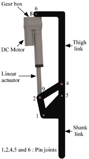
The figure 1 shows the knee exoskeleton designed by Jain et al. [22] consist of EMG sensor-based planar four-bar mechanism that is actuated by a linear DC motor. To evaluate the efficacy of the proposed design, the exoskeleton is integrated onto an artificial limb, and modeling and simulation studies are conducted using the bond graph technique across varying loads. Subsequently, a experimental investigations are performed to validate the desired torque generated by the actuator at the knee joint for performing the STS motion. Additionally, the dynamic simulation and experimental results indicate that the actuator force varies throughout the desired activity rather than remaining constant. Consequently, the assistive torque developed by the actuator at the knee joint of the exoskeleton is found to be suitable for providing optimal support to the wearer, necessitating minimal effort on their part to perform the stand-sit-stand motions. The CAD model for the knee exoskeleton was produced utilizing SolidWorks, as illustrated in Figure 1. This design is inspired by the work of Kim et al. [23] The proposed design is based on a planar four-bar mechanism actuated by a linear DC motor. It consist of universal design that allows it to be worn by anyone, irrespective of their leg length. The exoskeleton’s fifth joint is positioned at the wearer’s knee joint, while the shank length can be adjusted to fit the wearer’s calf length.
3 Kinematic Modelling
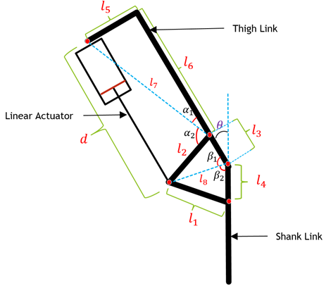
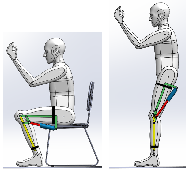
The Figure 2 describes a robotic exoskeleton intended to support human mobility. The core component of the exoskeleton is a four-bar mechanism inspired by Jain et al. This mechanism is composed of four rigid links, namely , , , and which are linked by four pin joints, forming a quadrilateral shape. The exoskeleton’s motion is driven by a linear DC motor, which, when activated, propels a piston that sets in motion a slewing bar (), causing the thigh link () to pivot around a specific point (5) while the shank link () remains attached to the ground (ankle). The design of the exoskeleton is based on a crank-rocker mechanism that meets Grashof’s criteria. This mechanism is characterized by a sum of the shortest and longest links ( and ) that is less than the sum of the other two links ( and ). Additionally, the link adjacent to the shortest link () remains fixed during STS motion. As a result of these features, the shortest link () acts as a crank, driving the mechanism’s motion. Meanwhile, the link next to the fixed link () behaves as a rocker, oscillating back and forth. The coordinated interplay between the links and the motor enables the exoskeleton to move its limbs, thus emulating the natural gait of humans.
The mathematical formulation based on the above exoskeleton are:
| (1) | |||
| (2) | |||
| (3) | |||
| (4) | |||
| (5) | |||
| (6) |
where is the angle between link and . is the angle between link and . is the angle between link and . is the angle between link and . is the knee joint angle. d is the stroke length of linear actuator.
4 Design Optimization
4.1 Problem Formulation
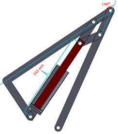
The angle of the knee joint in an exoskeleton is governed by a linear actuator. The maximum angle of rotation achievable by the knee joint is contingent on the minimum stroke length possible with the linear actuator. In the present setup, this minimum stroke length is 242 mm. The optimization of the six remaining links that indirectly impact the knee joint’s range of motion is essential to increase the latter. Our objective, therefore, is to maximize the objective function below to achieve this goal.
4.2 Design Variables
This optimization problem consists of six variables as shown below. The width of all the links are same.
Because of these six variables, the objection function must be in the form of
where d = = 242 mm [22]
4.3 Constrains
In this optimization, there are fifteen constrains:
-
1.
The four bar linkage consist of l1, l2, l3, l4 link. The four bar mechanism should follow the Grashof’s law i.e. the sum of shortest and largest link should be less than the sum of other two links:
-
2.
The above constrains follow the Grashof’s law but while designing we don’t have the information which is the shortest link in all four links:
-
3.
Similarly, we don’t have the information of longest link also. Therefore, we are adding below constrains:
-
4.
The width of the thigh of human beings is always less than the length of the thigh. Therefore, we are adding below constrains:
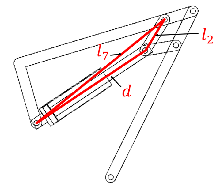
Figure 3: Sit position -
5.
Since, the optimization is purely based on geometrical approach, it is important to give constrains to knee joint angle. In real design there is limit to the range of motion. To do so, we have provided singularity constrain.. The figure 3 shows the position of links in the triangle when reaching at the maximum knee joint angle of exoskeleton. The further increment of angle reduces the angle between l7 and d. When the angle between link d and l2 becomes 180 deg. then it loses its 1 degree of freedom which convert the 1 degree of freedom mechanism into structure. Therefore, the mechanism become redundant if it satisfies the constrains = + .
-
6.
The optimized exoskeleton’s dimension can be scale up or down. To avoid these, we have set the boundaries of each variables. These boundaries are on the basis of measurement of leg dimension of average human being weighted 80 kg and 180 cm height:
5 Optimization method and Results
The proposed exoskeleton comprises of 6 links, and to obtain the optimal measurement for maximum range of motion for every user, synthesis of exoskeleton has been performed. The optimization of knee joint exoskeleton is a vital aspect of knee joint support. To achieve optimal outcomes, the Interior Point Method is utilized. This iterative algorithm is employed to solve convex optimization problems, unlike traditional simplex methods that traverse the edges of the feasible region. Interior point methods move through the interior of the feasible region towards the optimal solution, enabling efficient handling of large-scale problems with numerous constraints and variables. Barrier functions are utilized by interior point methods to enforce the feasibility of solutions. These functions penalize infeasible solutions, guiding the optimization process towards feasible regions.
Interior point techniques provide the ability to change the barrier according to the measurement of human limbs, and this technique presents many advantages such as efficiency, scalability, and robustness. Interior point methods exhibit polynomial-time complexity, making them suitable for large-scale optimization problems. These methods are robust against ill-conditioned problems and numerical instabilities, providing reliable solutions even in challenging scenarios. Interior point techniques scale well with problem size, enabling the optimization of high-dimensional problems encountered in modern applications such as machine learning and data analysis.
The optimization has been done using the Interior point method. This problem is non-linear inequality constrained. The interior point method which is type of barrier method doesn’t depend on the type of problem. i.e. it can be used for both for convex or non-convex problem.
| Design Variable | Initial value (in mm) | Optimum value (in mm) |
| 85 | 59.081 | |
| 85 | 68.84 | |
| 85 | 55.964 | |
| 80 | 71.849 | |
| 80 | 118.63 | |
| 235 | 287.31 |
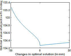
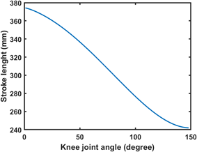
In order to optimize a given function, it is crucial to identify the optimal point and the corresponding minimum value. To achieve this, we adopt a conventional approach that involves stepping away from the optimal point and observing the changes that occur in the optimal solution. By doing so, we are able to obtain a more comprehensive understanding of the behaviour of the function and the impact of the surrounding environment on its performance. As an illustration, a figure 5 showcasing the function’s local minima demonstrates that the optimal values increase as we move away from the optimal point, which is situated at the centre of the x-axis. In the figure 6, the dependency of stroke length on the knee joint angle has been shown. This graph shows the non-linearly relationship between the stroke length and knee joint angle.
6 Graphical Simulation
In optimization, particularly in iterative approach, the global solution may not necessarily the correct solution. The global minima might not be feasible in the context of design of the exoskeleton.
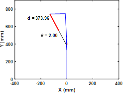
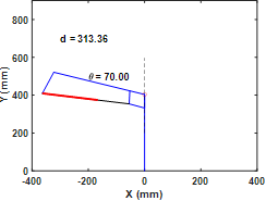
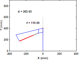
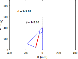
In optimization, particularly in iterative approach, the global solution may not necessarily the correct solution. The global minima might not be feasible in the context of design of the exoskeleton. The solution obtain is an approximate solution which is local minima as shown in the figure 5. To verify the practicality of the solution, author constructed a method in MATLAB to demonstrate the geometrical simulation based on optimal dimension which is shown in figure 7. In this figure, the ordinate and abscissa represents the dimensions of the links. The red circle shows the knee joint, around which the rotation will occur. In figure 7, there is 2 degree of rotation i.e. the human is almost standing. As the human start siting, the angle of rotation () increases as you can see in figure 8 and 9. The figure 10 shows the maximum angle achieved by the exoskeleton ( = ) before reaching the singularity position. The rotation of exoskeleton is actuated by linear actuator as shown in figure 7 to 10. The thick red line represent the cylinder of the linear actuator and black line represents piston. The combine length of piston and cylinder is represented as d in the figures. The figure 10 validate that the optimal design of exoskeleton with same stroke length (d) gives more range of rotation than previous design.
To check the practicality of proposed optimized Knee joint exoskeleton, Graphical simulation of exoskeleton with mannequin has been performed in SolidWorks. The mannequin is based on average adult human being. The above simulation shows the feasibility of the optimal dimension. The range of motion achieved by this method is 148 degrees which is 24.7 more than the previous work without optimization on this design. This comparison has been done on the basis of same stroke length. It means the maximum distance (242 mm) covered by linear actuator is same in both cases.
7 Gait Analysis
In this section, there is analysis of Sit to Stand motion of human being and LAKE. The Gait analysis is crucial while designing the exoskeleton.Understanding the gait mechanics is particularly important for designing exoskeletons used in rehabilitation. Gait analysis helps identify abnormal movement patterns and can guide the design of exoskeletons to correct these patterns, aiding in the recovery process. Additionally, it helps prevent further injuries by ensuring that the exoskeleton does not impose unnatural stresses on the body. Here by analyzing the individual gait pattern, the exoskeleton can be constructed with minimum misalignment.
To perform the gait analysis of human being for Sit to Stand motion, The author performed experiment in which subject is performing sit to stand motion. This motion has captured with the help of camera. Figure 13 illustrates the setup where the sit-to-stand motion was captured using a high-resolution camera. A reflective marker was strategically placed on the knee joint of the subject to ensure precise tracking. The TRACKER software processed the video footage frame by frame, extracting the trajectory data of the marker over time. The markers trajectory shown in figure are the trajectories of the joint. To analyse the motion of these coordinates, the angles has to be calculated.

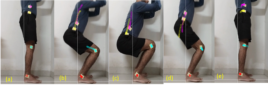
This was done by defining vectors between key anatomical landmarks: (ankle to knee), (knee to hip), and (hip to waist) as shown in fig 12. These vectors were used to determine the angular displacements and provide a comprehensive view of the joint mechanics. The Knee joint angle is calculated by formula
| (7) |
where, is knee joint angle. This thorough and systematic approach offers significant insights into the bio-mechanical interactions between human joints and exoskeleton systems, emphasizing the importance of precise alignment in enhancing the efficacy and safety of exoskeletons in practical applications.
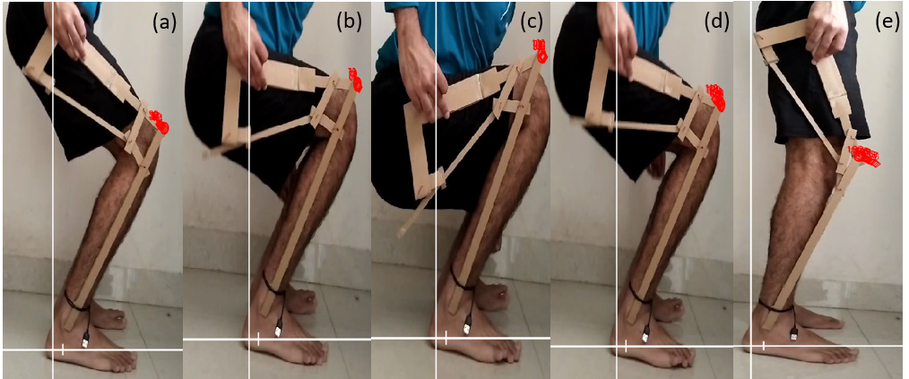
Similarly, same subject has performed the sit to stand motion with exoskeleton. This exoskeleton is dummy model made up from cardboard. Its sole purpose is to get the trajectory of optimized dimension based exoskeleton. In figure 14, subject is performing sit to stand motion with exoskeleton. The red mark on exoskeleton is exoskeleton’s knee joint. Here, it is an assumption that red mark act as knee joint. The actual knee joint can be instantaneous center of four bar linkage. It is because the instantaneous centre of four bar linkage follow the same trajectory as human’s knee joint during sit to stand motion.
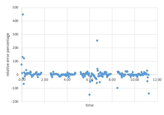
The data obtained from the experiment is used to draw the trajectory of the human’s knee joint and exoskeleton’s knee joint. The concept behind these generation of trajectories are to get some idea on misalignment between them. The yellow line trajectory shows the motion of knee joint during sit to stand motion as shown in figure 15. The orange line shows the trajectory of the exoskeleton’s knee joint. The figure 16 shows the relative error between both trajectories. Since, both trajectory are similar, the relative error is zero at most position. This similarity of trajectory shows that the better understanding of misalignment between them. This similarity also conclude that the misalignment is quite less between the subject and exoskeleton. The sudden spike in the error as shown in figure 16 is due to the human error during the experiment. During experiment, sudden changes in movement of subject or friction between the links can cause a slight deviation of position of exoskeleton’s knee joint.

8 Prototype Development
The prototype of Linear Actuator based Knee joint Exoskeleton (LAKE) has been developed. In this work, the micro-controller used is Arduino UNO as shown in figure 17. The Arduino UNO is an open-source electronics platform based on easy-to-use hardware and software.The primary purpose of the Arduino UNO is to facilitate the development of digital devices and interactive objects that can sense and control objects in the physical world.
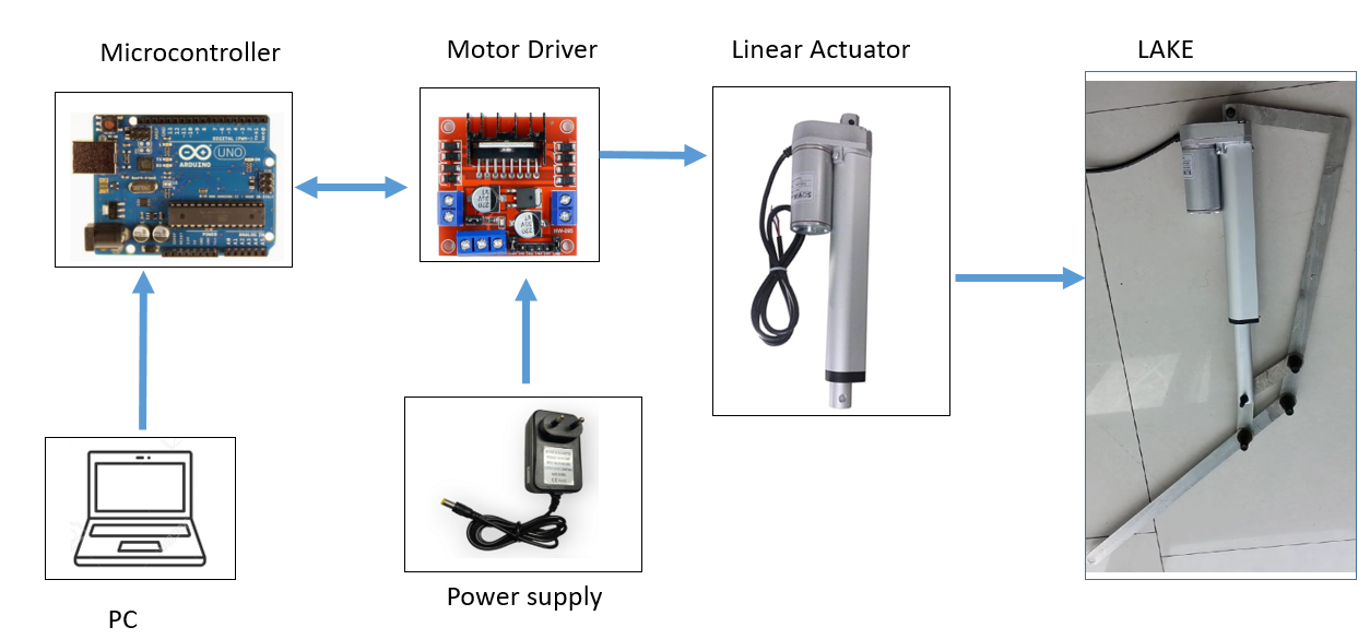
This Arduino works on 5V power supply. The power supply has been provided by Laptop. To control the Linear actuator, the motor driver L298N has been used. Motor drivers are crucial components in the field of electronics, particularly in robotics and automation. They serve as the intermediary between microcontrollers (such as Arduino boards) and motors, enabling the control of motor direction and speed. This is important because microcontrollers often cannot supply the necessary current to drive motors directly. Motor drivers amplify the control signals from the microcontroller to provide the appropriate power to the motors.The author used L298N motor driver because of its high current capability, as the L298N can drive motors with up to 2A of current per channel, accommodating a broad range of motor types and sizes. The module operates over a wide voltage range, handling motor supply voltages from 5V to 35V, which adds to its adaptability in various projects.
Speed control is another critical feature of the L298N, achieved through pulse-width modulation (PWM). By varying the duty cycle of the PWM signal applied to the enable pins (ENA and ENB), users can finely adjust motor speeds. The module also includes thermal protection to prevent damage from overheating, a crucial aspect for maintaining reliability and longevity in demanding applications. Additionally, the L298N is designed for easy integration with straightforward onboard terminals and connectors, simplifying connections to motors and power supplies. The power supply is given from adaptor which convert 220V AC into 12V 2A DC, which is suitable output for our motor driver.
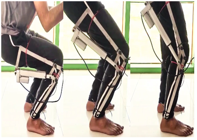
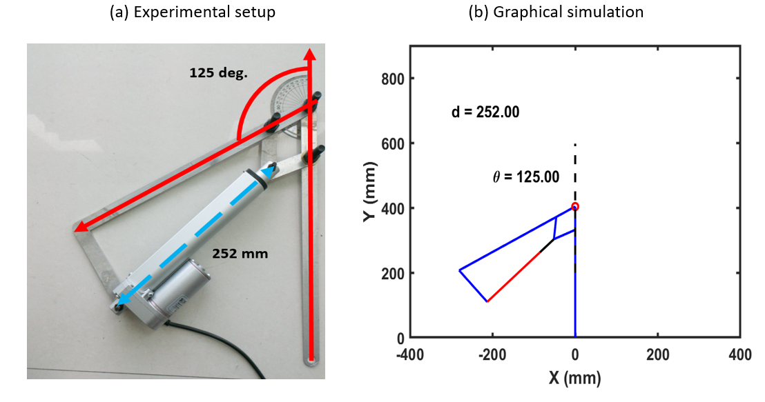
After assembling all the components shown in figure 17, the C based code has been written in Arduino IDE. This code is uploaded to the Arduino which drives the motor driver and further the exoskeleton as shown in figure LABEL:sts_exo. The exoskeleton wear by subject in figure LABEL:sts_exo is working at 5mm/s stroke velocity. There is no support except exoskeleton has been taken by subject. The forces generated by the actuation of actuator pushes the subject upward. Furthermore, this prototype has been used to validate the graphical simulation as shown previously in figure LABEL:fig12. The angle measured at given stroke length (252mm) as shown in figure 19 and the angle achieved during Graphical simulation by providing same stroke length (252mm) comes similar which verify our previous simulation and analysis.
9 Conclusion
The mechanical design of existing knee joint exoskeleton has been optimized for maximum range of motion during Sit to Stand motion. The optimization technique used is Interior Point method. The ranges used in this method can be change according to the measurements of the subject. Furthermore, the results have been shown by constructing the graphical simulation and simulation with mannequin. Additionally, The prototype has been developed on the basis of the optimization and simulations which verify the maximum range of motion of knee exoskeleton.
References
- [1] Narek Zakaryan, Mikayel Harutyunyan, and Yuri Sargsyan. Bio-inspired conceptual mechanical design and control of a new human upper limb exoskeleton. Robotics, 10(4):123, 2021.
- [2] Enrique Rodriguez, Baidya Nath Saha, Jesús Romero-Hdz, and David Ortega. A multiobjective differential evolution algorithm for robot inverse kinematics. SSRG International Journal of Computer Science and Engineering (SSRG-IJCSE), 3(5), 2016.
- [3] Chuanyin Tian, Zhibin Song, and Tianyu Ma. Mechanism design of a multifunctional motion assistant robot combined wheelchair and exoskeleton. In 2017 IEEE International Conference on Mechatronics and Automation (ICMA), pages 1521–1525. IEEE, 2017.
- [4] Carlos A Coello Coello. Evolutionary algorithms for solving multi-objective problems. Springer, 2007.
- [5] Zihao Du, Zefeng Yan, Tiantian Huang, Zhengguang Zhang, Ziquan Zhang, Ou Bai, Qin Huang, and Bin Han. Mechanical design and preliminary performance evaluation of a passive arm-support exoskeleton. In 2020 IEEE/RSJ International Conference on Intelligent Robots and Systems (IROS), pages 3371–3376. IEEE, 2020.
- [6] Houcheng Li, Long Cheng, Ning Sun, and Ran Cao. Design and control of an underactuated finger exoskeleton for assisting activities of daily living. IEEE/ASME Transactions on Mechatronics, 27(5):2699–2709, 2021.
- [7] Jaeyong Lee, Hyungjoo Kim, and Woosung Yang. Development of wrist interface based on fully actuated coaxial spherical parallel mechanism for force interaction. Sensors, 21(23):8073, 2021.
- [8] Justin Hunt, Panagiotis Artemiadis, and Hyunglae Lee. Optimizing stiffness of a novel parallel-actuated robotic shoulder exoskeleton for a desired task or workspace. In 2018 IEEE International Conference on Robotics and Automation (ICRA), pages 6745–6751. IEEE, 2018.
- [9] Benjamin DeBoer, Ali Hosseini, and Carlos Rossa. A discrete non-linear series elastic actuator for active ankle-foot orthoses. IEEE Robotics and Automation Letters, 7(3):6211–6217, 2022.
- [10] Diego F Paez-Granados, Hideki Kadone, Modar Hassan, Yang Chen, and Kenji Suzuki. Personal mobility with synchronous trunk–knee passive exoskeleton: Optimizing human–robot energy transfer. IEEE/ASME Transactions on Mechatronics, 27(5):3613–3623, 2022.
- [11] Rituraj Rituraj, Rudolf Scheidl, Peter Ladner, Martin Lauber, and Andreas Plöckinger. Prototyping and experimental investigation of digital hydraulically driven knee exoskeleton. Energies, 15(22):8695, 2022.
- [12] Martin Tschiersky, Edsko EG Hekman, Dannis M Brouwer, Just L Herder, and Koichi Suzumori. A compact mckibben muscle based bending actuator for close-to-body application in assistive wearable robots. IEEE Robotics and automation letters, 5(2):3042–3049, 2020.
- [13] Jiazheng Du, Yu Tian, Dagan Zhang, Hongbo Wang, Yongshun Zhang, Bo Cheng, and Jianye Niu. Mechanism design and performance analysis of a wearable hand rehabilitation robot. Machines, 10(12):1211, 2022.
- [14] Andrew J McDaid. Design, analysis, and multicriteria optimization of an overground pediatric robotic gait trainer. IEEE/ASME Transactions on Mechatronics, 22(4):1674–1684, 2017.
- [15] Ahmed Asker, Shengquan Xie, and Abbas A Dehghani-Sanij. Multi-objective optimization of force transmission quality and joint misalignment of a 5-bar knee exoskeleton. In 2021 IEEE/ASME International Conference on Advanced Intelligent Mechatronics (AIM), pages 122–127. IEEE, 2021.
- [16] Shui Yu. Reliability-based design optimization for the knee joint of the lower extremity exoskeleton. In 2018 Annual Reliability and Maintainability Symposium (RAMS), pages 1–5. IEEE, 2018.
- [17] Jihwan Yoon, Sumin Kim, Junyoung Moon, Jehyeok Kim, and Giuk Lee. Minimizing misalignment and frame protrusion of shoulder exoskeleton via optimization for reducing interaction force and minimizing volume. Machines, 10(12):1223, 2022.
- [18] M Bianchi, M Cempini, R Conti, E Meli, A Ridolfi, N Vitiello, and B Allotta. Design of a series elastic transmission for hand exoskeletons. Mechatronics, 51:8–18, 2018.
- [19] E Amirpour, M Savabi, A Saboukhi, M Rahimi Gorji, H Ghafarirad, R Fesharakifard, and S Mehdi Rezaei. Design and optimization of a multi-dof hand exoskeleton for haptic applications. In 2019 7th International Conference on Robotics and Mechatronics (ICRoM), pages 270–275. IEEE, 2019.
- [20] Beatrice Malizia, Partha Ryali, and James Patton. Passive exotendon spring elements can replace muscle torque during gait. In 2020 8th IEEE RAS/EMBS International Conference for Biomedical Robotics and Biomechatronics (BioRob), pages 773–778. IEEE, 2020.
- [21] Chao Qin, Peng Li, Xiaojun Yang, and Bing Li. A design of hand rehabilitation exoskeleton mechanism adapted to different finger lengths. In 2019 IEEE International Conference on Robotics and Biomimetics (ROBIO), pages 1621–1626. IEEE, 2019.
- [22] Prakhar Jain, Tarun Kumar Bera, Ashish Singla, and Magnus Isaksson. Linear actuator–based knee exoskeleton for stand–sit–stand motions: a bond graph approach. SIMULATION, 98(8):627–644, 2022.
- [23] Hyo-gon Kim, Sangdeok Park, and Changsoo Han. Design of a novel knee joint for an exoskeleton with good energy efficiency for load-carrying augmentation. Journal of Mechanical Science and Technology, 28:4361–4367, 2014.