Designing a compact cavity-enhanced source of entangled photons
Abstract
Quantum repeaters will require sources of entanglement allowing efficient coupling to quantum memories. Here, we address this challenge with a compact, narrowband source design. The entangled pairs are generated via SPDC in two perpendicularly oriented nonlinear crystals in a Fabry-Pérot cavity. We show that the case of highly non-degenerate wavelengths and type-II phase matching is the most promising candidate for a practical implementation. Using the parameters of an experiment we are currently working on, this design should allow generating entangled photons with a bandwidth of a few MHz.
pacs:
03.65.Ud, 03.67.Hk, 03.65.Ud, 42.50.Pq, 42.50.-p, 42.79.GnLarge-scale quantum networks will use entanglement as a resource for future quantum applications Horodecki et al. (2009); Wehner et al. (2018). Establishing such networks is a challenge due to the losses in the optical links connecting the individual nodes. The distribution of entanglement has been demonstrated successfully over a few hundred kilometers in optical fiber networks Neumann et al. (2022); Zhuang et al. (2024). Using optical satellite links allows for the distribution over even larger distances, but at the cost of significant losses Yin et al. (2017); Sidhu et al. (2021); Kržič et al. (2023). In optical fibre networks, the range achievable for entanglement distribution can be increased by using quantum repeaters Briegel et al. (1998). These combine entanglement distillation and purification Bennett et al. (1996); Deutsch et al. (1996); Wootters (1998) with entanglement swapping Żukowski et al. (1993) to distribute high-fidelity entanglement over large distances. To avoid exponential loss, the entanglement needs to be stored efficiently until the intermediate steps have been completed successfully Bennett et al. (1996).
Using narrowband sources of entanglement is beneficial for several purposes. It can increase the efficiency of storing entangled photons in quantum memories Wang et al. (2019); Heller et al. (2022) and it can reduce the background in the day-light operation of free-space links Aspelmeyer et al. (2003); Kržič et al. (2023). Moreover, using narrowband modes allows for frequency division multiplexing. This can increase the bandwidth of quantum channels and allows the simultaneous connection of multiple network clients Neumann et al. (2022). Generating narrowband photons can be achieved using cavity-enhanced spontaneous parametric downconversion (SPDC) Chuu et al. (2012); Lenhard et al. (2015). Other methods include spontaneous four-wave mixing in hot atomic vapor cells Zhu et al. (2017); Hsu et al. (2021) or using laser-cooled atoms Wang et al. (2022); Bruns et al. (2022). Recent works showed the generation of photon pairs compatible with the storage in atom-based quantum memories Tsai and Chen (2018); Prakash et al. (2019); He et al. (2023) and in solid-state quantum memories Liu et al. (2020); Onozawa et al. (2022). In some cases, the actual storage of single photons in quantum memories has already been achieved Mannami et al. (2021); Buser et al. (2022); Ito et al. (2023).
Generating entanglement, however, requires making two biphoton processes indistinguishable. For example, by exciting indistinguishable processes in a single SPDC crystal Kwiat et al. (1995), or by creating a superposition of two-photon amplitudes originating in multiple crystals Kwiat et al. (1999); Ljunggren and Tengner (2005). Alternatively, the amplitudes can originate from multiple branches in an interferometer Fedrizzi et al. (2007). Recently, there has been significant progress in simultaneously achieving entanglement and narrow bandwidth of the generated photons. In Ref. Gao et al. (2024), the light from two cavity-enhanced SPDC crystals was used to generate entanglement with sub-GHz bandwidth in an interferometric setup. Refs. Niizeki et al. (2020); Ito et al. (2023) showed the generation of narrowband entanglement using a frequency comb. These photons then were frequency converted to a wavelength compatible with solid-state quantum memories. The authors of Ref. Arenskötter et al. (2023) used a single crystal in a bi-directionally pumped bow-tie cavity to generate entangled photons compatible with a quantum memory.
Here, we present the design of a compact, cavity-enhanced SPDC source of entangled photons without the need for complex interferometric or cavity setups. We will consider realistic experimental parameters to investigate the feasibility of achieving narrowband entanglement using a comparatively simple design. The source (Fig. 1) is based on a single cavity that contains two nonlinear crystals rotated by 90 degrees relative to each other, inspired by Ljunggren et al. (2006); Trojek and Weinfurter (2008); Chuu and Harris (2011); Chuu et al. (2012). The crystals can be of different lengths, and . We pump the crystals with light at frequency and with the polarization chosen to balance the brightness of both SPDC processes.
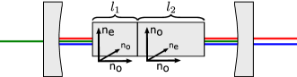
Depending on its polarization, the pump photon will create a pair of SPDC photons in the first or the second crystal. These photons are denoted as the signal and the idler with frequencies and , respectively. Like the crystal axes, the polarization directions of the photons created in the first crystal will be perpendicular to those created in the second crystal.
Since the pump photon can generate an SPDC pair either in the first or in the second crystal, the corresponding two-photon state will be a linear combination of these two processes:
| (1) |
is a relative phase and is a boson creation operator of mode at frequency . can indicate the polarization or the crystal of origin. The polarization of the photons generated is determined by the PM condition. For type-II SPDC, the state will be a superposition of the Bell states , while it will be a superposition of Bell states for type-0 and type-I SPDC 111 and . If the signal and idler photons originate from type-II SPDC and have degenerate frequencies, the amplitudes from different crystals will result in a product state . Using our source design with type-II PM to generate entanglement is therefore not possible for degenerate frequencies. For type-0 and type-I SPDC, one cannot spatially separate the photons if the frequencies are degenerate. For these reasons, we will focus on two specific cases: (1) the photons produced have near-degenerate wavelengths suitable for the low-loss distribution in telecommunication fibers, (2) only one photon is at such a telecommunication wavelength, and the second one has a wavelength suitable for efficiently coupling to a quantum memory.
Typically, the bandwidth of SPDC photons is much broader than the acceptance bandwidth of quantum memories Wang et al. (2019); Heller et al. (2022). The effective bandwidth can be reduced by coupling the process to an optical cavity Boyd and Ashkin (1966); Chuu and Harris (2011); Chuu et al. (2012); Tsai and Chen (2018). Only the portions of the photon spectra that are resonant with the narrow cavity modes will be enhanced. In comparison, the remainder of the spectra will be strongly suppressed. For each mode, denoted by an index , we can define the mode number , which is the phase shift that light in mode acquires during one cavity round trip. For example, in the case of a two-crystal type-II source, the four corresponding mode numbers are:
| (2) |
Here, and represent the downconverted signal and idler mode numbers originating in the first crystal, while and represent the equivalent mode numbers for the second crystal. A single mode is resonant with the cavity if its frequency is an integer multiple of the free spectral range . Here, denotes the partial derivative with respect to . To achieve narrowband entanglement between photons in these four modes, all of them have to be resonant with the cavity simultaneously. We denote this as a quadruple resonance.
Due to the frequency-dependent birefringence of the crystals, and due to their different lengths, the FSRs of the downconverted modes will be different. Simultaneous resonances of multiple modes will occur only at specific frequency spacings much greater than individual FSRs. This is known as cluster spacing. The cluster spacing of a double resonance between modes and can be expressed in terms of their FSRs Chuu and Harris (2011); Chuu et al. (2012):
| (3) |
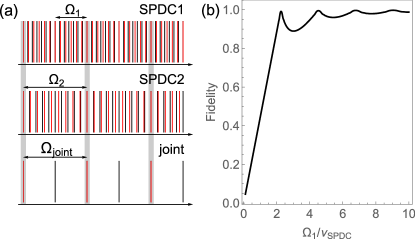
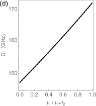
Similarly, the cluster spacing is calculated for the modes and . For quadruple resonances, we define the joint cluster spacing by replacing and in Eq. 3 with and , respectively. Fig. 2(a) illustrates this relationship.
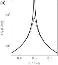
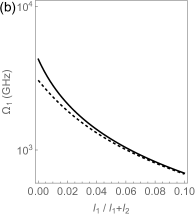
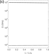
One wants to have the joint cluster spacing small enough such that finding a quadruple resonance is achievable by tuning control parameters within a parameter range that is experimentally feasible. An additional challenge is finding the right ratio between the cluster spacing and the SPDC bandwidth. If the cluster spacing in an individual crystal is smaller than the corresponding SPDC bandwidth, multiple cavity modes at different frequencies will be enhanced. The output state of the cavity-enhanced SPDC in crystal will then be a linear combination of these modes: . Here, are normalized amplitudes depending on the phase mismatch of the SPDC process (see Appendix A). denotes crystal or . Fig. 2(b) shows the calculated fidelity of the output state of crystal 1 for type-II PM with a product state as a function of cluster spacing normalized to the SPDC bandwidth. The plot shows that a fidelity larger than 0.9 is achieved for
| (4) |
This gives us a target bound for the source design if no additional spectral filtering is used.
In the following, we will assume realistic experimental parameters and analyze the feasibility of the source design for the cases of near-degenerate and highly non-degenerate frequencies using type-0 and type-II PM. For the SPDC crystals, we assume MgO-doped periodically poled Lithium Niobate (PPLN) due to its high nonlinearity and transparency at nm Gayer et al. (2008).
First, let us consider a near-degenerate source. We assume a pump wavelength of nm and near-degenerate signal and idler modes at . corresponds to a small frequency shift MHz.
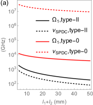
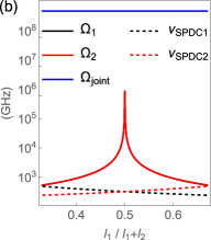
Fig. 3(a) shows the SPDC bandwidth and the cluster spacing of the modes originating in crystal 1 for type-II and type-0 PM, as a function of the joint crystal length 222Type-0 cluster spacing was calculated using a second order expansion, see Appendix C. For the SPDC photons originating in crystal 2, identical considerations can be made.. For type-0 SPDC, the bandwidth and the cluster spacing are exceedingly high, whereas for type-II SPDC, the SPDC bandwidth is notably less than the cluster spacing. This means that a source based on type-0 PM is not possible but a setup based on type-II may be feasible. In particular, using type-II PM can ensure that cavity enhancement is achieved for the intended single pair of frequencies with high fidelity.
Generating entangled pairs, however, requires a quadruple resonance, and we will see in the following that this is not possible for a near-degenerate source even for type-II PM. Fig. 3(b) shows that the cluster spacings of the double resonances grow significantly as the ratio of approaches . At this point, the four crystal modes nearly become degenerate for small . One can see that the joint cluster spacing is extremely large for all length ratios. Two quadruple resonances would be displaced by a wavelength shift of more than m. A type-II near-degenerate source could therefore produce narrowband photon pairs, but an entangled state cannot be achieved since one cannot find a quadruple resonance in practice.
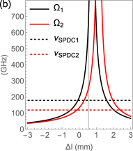
Secondly, let us consider the case of a highly non-degenerate source. We assume a pump wavelength of nm to generate signal photons at the Rubidium transition nm and idler photons at nm.
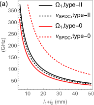
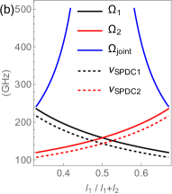
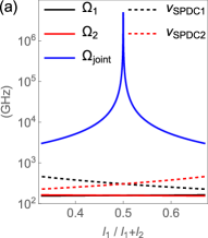
Fig. 4(a) shows the SPDC bandwidth and the cluster spacing of a double resonance in crystal 1 as a function of the joint crystal length. Note that both the cluster spacing and the SPDC bandwidth reduce as the crystal length increases. For both types of phase matching, the SPDC bandwidth is too large to generate photon pairs where the frequency of each individual photon is well defined. The corresponding fidelity will therefore be only for a type-II source and for a type-0 source (see Fig. 2(b)). Type-0 PM has the additional disadvantage that the joint cluster spacing is on the order of THz (see Appendix B). This makes it impossible to find the quadruple resonances necessary for generating entangled photon pairs.
We will therefore focus on finding quadruple resonances for the more favorable type-II PM. To achieve that, we investigate the dependence of the joint cluster spacing on the ratio of the crystal lengths as shown in Fig. 4(b). If the crystal lengths are the same, the joint cluster spacing will diverge since the two pairs of cavity modes become identical and will have the same cluster spacing for double resonances. To allow finding a quadruple resonance to generate entangled states, we therefore choose crystals of differing lengths. Even then, the SPDC processes in the individual crystals can still produce photons in multiple frequency modes.
One solution is to introduce additional filtering of the cavity output. The practicality of this solution will depend on the spacing of the double resonances. Alternatively, one can introduce a relative optical path delay to idler modes and while keeping the signal modes unchanged. We model this path delay by adding to . This will leave the SPDC bandwidths and the joint cluster spacing unchanged, but it will affect the cluster spacings for the SPDC processes in the individual crystals. Using this approach and m, one can achieve a fidelity of of the state generated with the targeted polarization entangled state as in Eq. 1 (see Appendix D).
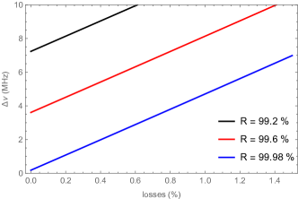
The bandwidth of the state the source will generate depends on the cavity linewidth, which is determined by the intracavity losses and the cavity length. To provide a numeric estimate, let us assume the nonlinear crystals to be PPLN with a joint crystal length of mm. This will determine the optimal length of the cavity (mm) in reference to the focusing parameter Boyd and Ashkin (1966). For mirror reflectivites of , achieving a bandwidth of MHz will require a finesse of . This gives an upper boundary of for the intracavity losses. Achieving such low losses is possible by picking appropriate anti-reflection coatings for PPLN. For additional details, see Appendix E.
We presented a design for a compact cavity-enhanced source of polarization-entangled photons. The photon pairs are generated in two nonlinear crystals with perpendicular optical axes inside a single Fabry-Pérot cavity. We studied the feasibility of the design for different types of phase matching and for near-degenerate as well as highly non-degenerate wavelengths. The combination of type-II phase matching and highly-nondegenerate wavelengths should allow the generation of high-fidelity narrowband entangled photon pairs for realistic experimental parameters. The presented design is the basis for an experimental realization we are currently working on. In addition to the considerations presented here, an actual implementation will require a high-precision control of experimental parameters to find and actively stay on the necessary quadruple resonance of the cavity. This will include the stabilization of the crystal temperatures, the cavity length, and the pump wavelength.
Acknowledgements.
ŽP and RK acknowledge support by the Slovenian Research Agency under contracts no. J2-2514, N1-0180, P1-0416, J1-9145, P1-0125. LU acknowledges funding by the Slovenian Research Agency under contracts no. J1-2458 and P1-0416. All authors were supported by the Republic of Slovenia (MVZI) and the European Union - NextGenerationEU (SiQUID-101091560).References
- Horodecki et al. (2009) R. Horodecki, P. Horodecki, M. Horodecki, and K. Horodecki, Reviews of Modern Physics 81, 865 (2009), publisher: American Physical Society.
- Wehner et al. (2018) S. Wehner, D. Elkouss, and R. Hanson, Science 362 (2018), 10.1126/science.aam9288, publisher: American Association for the Advancement of Science Section: Review.
- Neumann et al. (2022) S. P. Neumann, A. Buchner, L. Bulla, M. Bohmann, and R. Ursin, Nature Communications 13 (2022), 10.1038/s41467-022-33919-0.
- Zhuang et al. (2024) S.-C. Zhuang, B. Li, M.-Y. Zheng, Y.-X. Zeng, H.-N. Wu, G.-B. Li, Q. Yao, X.-P. Xie, Y.-H. Li, H. Qin, L.-X. You, F.-H. Xu, J. Yin, Y. Cao, Q. Zhang, C.-Z. Peng, and J.-W. Pan, “Ultrabright-entanglement-based quantum key distribution over a 404-km-long optical fiber,” (2024), arXiv:2408.04361 [quant-ph].
- Yin et al. (2017) J. Yin, Y. Cao, Y.-H. Li, S.-K. Liao, L. Zhang, J.-G. Ren, W.-Q. Cai, W.-Y. Liu, B. Li, H. Dai, G.-B. Li, Q.-M. Lu, Y.-H. Gong, Y. Xu, S.-L. Li, F.-Z. Li, Y.-Y. Yin, Z.-Q. Jiang, M. Li, J.-J. Jia, G. Ren, D. He, Y.-L. Zhou, X.-X. Zhang, N. Wang, X. Chang, Z.-C. Zhu, N.-L. Liu, Y.-A. Chen, C.-Y. Lu, R. Shu, C.-Z. Peng, J.-Y. Wang, and J.-W. Pan, Science 356, 1140 (2017).
- Sidhu et al. (2021) J. S. Sidhu, S. K. Joshi, M. Gündoğan, T. Brougham, D. Lowndes, L. Mazzarella, M. Krutzik, S. Mohapatra, D. Dequal, G. Vallone, P. Villoresi, A. Ling, T. Jennewein, M. Mohageg, J. G. Rarity, I. Fuentes, S. Pirandola, and D. K. L. Oi, IET Quantum Communication 2, 182 (2021), _eprint: https://onlinelibrary.wiley.com/doi/pdf/10.1049/qtc2.12015.
- Kržič et al. (2023) A. Kržič, S. Sharma, C. Spiess, U. Chandrashekara, S. Töpfer, G. Sauer, L. J. González-Martín del Campo, T. Kopf, S. Petscharnig, T. Grafenauer, R. Lieger, B. Ömer, C. Pacher, R. Berlich, T. Peschel, C. Damm, S. Risse, M. Goy, D. Rieländer, A. Tünnermann, and F. Steinlechner, npj Quantum Information 9, 1 (2023), publisher: Nature Publishing Group.
- Briegel et al. (1998) H.-J. Briegel, W. Dür, J. I. Cirac, and P. Zoller, Phys. Rev. Lett. 81, 5932 (1998).
- Bennett et al. (1996) C. H. Bennett, G. Brassard, S. Popescu, B. Schumacher, J. A. Smolin, and W. K. Wootters, Phys. Rev. Lett. 76, 722 (1996).
- Deutsch et al. (1996) D. Deutsch, A. Ekert, R. Jozsa, C. Macchiavello, S. Popescu, and A. Sanpera, Physical Review Letters 77, 2818 (1996), publisher: American Physical Society.
- Wootters (1998) W. K. Wootters, Physical Review Letters 80, 2245 (1998), publisher: American Physical Society.
- Żukowski et al. (1993) M. Żukowski, A. Zeilinger, M. A. Horne, and A. K. Ekert, Phys. Rev. Lett. 71, 4287 (1993).
- Wang et al. (2019) Y. Wang, J. Li, S. Zhang, K. Su, Y. Zhou, K. Liao, S. Du, H. Yan, and S.-L. Zhu, Nature Photonics 13, 346 (2019), publisher: Nature Publishing Group.
- Heller et al. (2022) L. Heller, J. Lowinski, K. Theophilo, A. Padrón-Brito, and H. de Riedmatten, Physical Review Applied 18, 024036 (2022), publisher: American Physical Society.
- Aspelmeyer et al. (2003) M. Aspelmeyer, H. R. Böhm, T. Gyatso, T. Jennewein, R. Kaltenbaek, M. Lindenthal, G. Molina-Terriza, A. Poppe, K. J. Resch, M. Taraba, R. Ursin, P. Walther, and A. Zeilinger, Science 301, 621 (2003).
- Chuu et al. (2012) C.-S. Chuu, G. Y. Yin, and S. E. Harris, Applied Physics Letters 101, 051108 (2012).
- Lenhard et al. (2015) A. Lenhard, M. Bock, C. Becher, S. Kucera, J. Brito, P. Eich, P. Müller, and J. Eschner, Physical Review A 92, 063827 (2015), publisher: American Physical Society.
- Zhu et al. (2017) L. Zhu, X. Guo, C. Shu, H. Jeong, and S. Du, Applied Physics Letters 110 (2017), 10.1063/1.4980073.
- Hsu et al. (2021) C.-Y. Hsu, Y.-S. Wang, J.-M. Chen, F.-C. Huang, Y.-T. Ke, E. K. Huang, W. Hung, K.-L. Chao, S.-S. Hsiao, Y.-H. Chen, C.-S. Chuu, Y.-C. Chen, Y.-F. Chen, and I. A. Yu, Optics Express 29, 4632 (2021).
- Wang et al. (2022) Y.-S. Wang, K.-B. Li, C.-F. Chang, T.-W. Lin, J.-Q. Li, S.-S. Hsiao, J.-M. Chen, Y.-H. Lai, Y.-C. Chen, Y.-F. Chen, C.-S. Chuu, and I. A. Yu, APL Photonics 7, 126102 (2022).
- Bruns et al. (2022) A. Bruns, C.-Y. Hsu, S. Stryzhenko, E. Giese, L. P. Yatsenko, I. A. Yu, T. Halfmann, and T. Peters, Quantum Science and Technology 8, 015002 (2022).
- Tsai and Chen (2018) P.-J. Tsai and Y.-C. Chen, Quantum Science and Technology 3, 034005 (2018).
- Prakash et al. (2019) V. Prakash, L. C. Bianchet, M. T. Cuairan, P. Gomez, N. Bruno, and M. W. Mitchell, Optics Express 27, 38463 (2019).
- He et al. (2023) H. He, P.-F. Yang, P.-F. Zhang, G. Li, and T.-C. Zhang, Frontiers of Physics 18 (2023), 10.1007/s11467-023-1317-z.
- Liu et al. (2020) J. Liu, J. Liu, P. Yu, and G. Zhang, APL Photonics 5 (2020), 10.1063/5.0006021.
- Onozawa et al. (2022) R. Onozawa, D. Yoshida, K. Niizeki, and T. Horikiri, Japanese Journal of Applied Physics 61, 102008 (2022).
- Mannami et al. (2021) K. Mannami, T. Kondo, T. Tsuno, T. Miyashita, D. Yoshida, K. Ito, K. Niizeki, I. Nakamura, F.-L. Hong, and T. Horikiri, Optics Express 29, 41522 (2021).
- Buser et al. (2022) G. Buser, R. Mottola, B. Cotting, J. Wolters, and P. Treutlein, PRX Quantum 3, 020349 (2022).
- Ito et al. (2023) K. Ito, T. Kondo, K. Mannami, K. Niizeki, D. Yoshida, K. Minaguchi, M. Zheng, X. Xie, F.-L. Hong, and T. Horikiri, Phys. Rev. Appl. 19, 024070 (2023).
- Kwiat et al. (1995) P. G. Kwiat, K. Mattle, H. Weinfurter, A. Zeilinger, A. V. Sergienko, and Y. Shih, Physical Review Letters 75, 4337 (1995), publisher: American Physical Society.
- Kwiat et al. (1999) P. G. Kwiat, E. Waks, A. G. White, I. Appelbaum, and P. H. Eberhard, Phys. Rev. A 60, R773 (1999).
- Ljunggren and Tengner (2005) D. Ljunggren and M. Tengner, Phys. Rev. A 72, 062301 (2005).
- Fedrizzi et al. (2007) A. Fedrizzi, T. Herbst, A. Poppe, T. Jennewein, and A. Zeilinger, Optics Express 15, 15377 (2007), publisher: Optica Publishing Group.
- Gao et al. (2024) M.-Y. Gao, Y.-H. Li, Y. Li, Z. Zhou, G.-C. Guo, Z.-Y. Zhou, and B.-S. Shi, Phys. Rev. A 109, 033720 (2024).
- Niizeki et al. (2020) K. Niizeki, D. Yoshida, K. Ito, I. Nakamura, N. Takei, K. Okamura, M.-Y. Zheng, X.-P. Xie, and T. Horikiri, Communications Physics 3, 138 (2020).
- Arenskötter et al. (2023) E. Arenskötter, T. Bauer, S. Kucera, M. Bock, J. Eschner, and C. Becher, npj Quantum Information 9 (2023), 10.1038/s41534-023-00701-z.
- Ljunggren et al. (2006) D. Ljunggren, M. Tengner, P. Marsden, and M. Pelton, Phys. Rev. A 73, 032326 (2006).
- Trojek and Weinfurter (2008) P. Trojek and H. Weinfurter, Applied Physics Letters 92, 211103 (2008).
- Chuu and Harris (2011) C.-S. Chuu and S. E. Harris, Phys. Rev. A 83, 061803 (2011).
- Note (1) and .
- Boyd and Ashkin (1966) G. D. Boyd and A. Ashkin, Phys. Rev. 146, 187 (1966).
- Gayer et al. (2008) O. Gayer, Z. Sacks, E. Galun, and A. Arie, Applied Physics B 91, 343 (2008).
- Note (2) Type-0 cluster spacing was calculated using a second order expansion, see Appendix C. For the SPDC photons originating in crystal 2, identical considerations can be made.
- Jundt (1997) D. H. Jundt, Opt. Lett. 22, 1553 (1997).
- Eckardt et al. (1991) R. C. Eckardt, C. D. Nabors, W. J. Kozlovsky, and R. L. Byer, J. Opt. Soc. Am. B 8, 646 (1991).
- Ismail et al. (2016) N. Ismail, C. C. Kores, D. Geskus, and M. Pollnau, Opt. Express 24, 16366 (2016).
- Boyd and Kleinman (1968) G. D. Boyd and D. A. Kleinman, Journal of Applied Physics 39, 3597 (1968).
Appendix A Phase-mismatch and bandwidth
The bandwidth of a single-pass SPDC is determined by the phase mismatch of the nonlinear process . Here, is the periodic poling of the SPDC crystal. The amplitude of the photons generated in a crystal of length is proportional to with . The FWHM bandwidth of the SPDC photons can then be determined from . Expanding up to linear order in signal frequency and temperature yields:
| (5) |
Here, is the crystal temperature, which affects the refractive index and the poling of the nonlinear crystal Jundt (1997); Gayer et al. (2008). The SPDC bandwidth is then determined from the solution of Eq. 5 as 2 .
Appendix B Additional cluster spacing plots
Appendix C Cluster spacing using higher-order approximations
In the main text, we used a linear approximation for calculating the cluster spacing. For most of the cases we considered there, this approximation yields the same results as a more detailed, higher-order calculation. The latter uses the definition of cluster spacing by Eckardt et al Eckardt et al. (1991). They found that the sum of two mode numbers will always be very close to an integer value if one is on a double resonance. This results from the fact that the sum of the signal and idler frequencies has to be equal to the pump frequency.
The cluster spacing can then be determined from an integer change in the joint mode number:
| (6) |
Apart from the frequencies of the optical modes involved, the cluster spacing can also depend on other system parameters. To take this into account, Eckert et al Eckardt et al. (1991) expand the joint mode number to second order in frequency and to first order in other parameters like, e.g., the crystal temperature :
| (7) |
Using the following relation resulting from energy conservation:
| (8) |
one can calculate the partial derivatives occurring in Eq. 7:
| (9) | ||||
The cluster spacing can be calculated by solving Eq. 6. This yields four possible solutions. We consider the solution yielding the lowest cluster spacing frequency because this determines the distance to the next closest cluster. In Fig. 6, we provide a comparison of the cluster spacing using the linear approximation of Eq. 3 in the main text and the cluster spacing derived from integer changes of the joint mode number. One can see deviations between the solutions for the first and second-order approximations close to parameters where the cluster spacing diverges. Examples are the case of a near-degenerate source close to equal crystal lengths () and the case of non-degenerate frequencies at .
Appendix D The fidelity with the target Bell state
In order to quantify the quality of the state produced by the source, we calculate its fidelity with the polarization-entangled Bell state we target. Here, we will assume . The biphotons generated will be a superposition of two-photon amplitudes of SPDC processes in crystal 1 and 2 for all possible frequency combinations of signal and idler photons within the SPDC bandwidth. These amplitudes will only couple efficiently to a cavity mode if the respective frequencies are resonant with the cavity. For type-II phase matching, we can write the two-photon state as:
| (10) |
Here, we assume that and both are resonant with the cavity. The amplitude for a given combination of signal and idler frequencies to the overall state is given by the normalized amplitude of the SPDC process at that frequency. The index denotes whether the SPDC process is happening in the first or the second crystal. If there is only one crystal as in the example in the main text, one can drop the index and write instead. To first order, the phase mismatch is equal to:
| (11) |
The pump polarization is chosen such that the absolute values of the amplitudes for the central frequencies are equal (), and that their relative phase matches that of the target Bell state. For example, for . All of the other frequency contributions with lower the fidelity with the targeted Bell state, .
Appendix E The minimum linewidth in a cavity
The goal of the present paper has been to describe the design of a source of entangled photons allowing efficient coupling to quantum memories. This coupling efficiency will be better the narrower the photon bandwidth. However, that bandwidth has to balance two contrary needs: a high rate of entangled pairs to overcome losses and a good coupling efficiency to quantum memories. Here, we assume a bandwidth of MHz to be a reasonable compromise. For example, this will allow good coupling to Rb quantum memories Prakash et al. (2019); Wang et al. (2019).
The bandwidth achievable for the photon pairs produced will be determined by the properties of the cavity. In particular, it is related to the finesse, which is defined as:
| (12) |
where is the FWHM linewidth of the cavity, and . The dependence of the finesse on the cavity length and its relation to the cavity linewidth are shown in Fig. 7. Of course, increasing the cavity length too much will contradict our goal of building a compact source of entangled photons.
To keep the source as compact as possible, one has to find other means of increasing the cavity finesse. The finesse depends on the mirror reflectivities and and the intracavity losses in the following way:
| (13) |
A derivation of an equivalent expression for the finesse can be found in Ref. Ismail et al. (2016). Increasing the finesse can be achieved by choosing high reflectivities for the cavity mirrors, high-quality antireflection coatings for the crystal end faces and low-absorption nonlinear crystals.
Let us now estimate an upper limit on the reflectivities of the antireflection coating for the wavelengths of the SPDC photons. To this end, we fix the two mirror reflectivities to be the same () and then calculate the linewidth as a function of the corresponding intra-cavity losses using Eq. (12). & (13). In Fig. 8, this dependence is shown for a cm long PPLN crystal and for several choices of mirror reflectivities. We neglected the losses in PPLN compared to the losses due to the anti-reflection coatings. The cavity length is determined by first finding the optimal focusing condition Boyd and Kleinman (1968) and then matching the curvature of the optimally focused beam to the curvature of the cavity mirrors, which we assume to be mm. By also taking into account the refractive index of PPLN, we get an effective cavity length of mm.