Development and Implementation of Advanced Beam Diagnostic
and Abort Systems in SuperKEKB
Abstract
The SuperKEKB/Belle II experiment aims to collect high-statistics data of B meson pairs to explore new physics beyond the Standard Model (SM). SuperKEKB, an upgraded version of the KEKB accelerator, has achieved a world-record luminosity of in 2022 but continues to strive for higher luminosities. One of the major obstacles is Sudden Beam Loss (SBL) events, which cause substantial beam losses and damage to the Belle II detector. To find a hint for addressing SBL challenges, advanced beam diagnostic systems and enhanced beam abort systems have been developed. The diagnostic system aims to accurately pinpoint the start of beam losses, while the upgraded abort system quickly disposes of anomalous beams to minimize damage.
This paper details the development and implementation of these systems, including high-speed loss monitors, time synchronization with the White Rabbit system, and data acquisition systems. Efforts to understand the mechanisms of SBL events, using acoustic sensors to detect discharges, are also discussed. These measures aim to improve the operational stability and luminosity of SuperKEKB, contributing to the experiment’s success.
keywords:
Loss Monitors , Belle II , SuperKEKB , Beam Abort , Beam Monitor , Beam Diagnostics , EMT , Sudden Beam Loss , White Rabbit , Movable Collimators1 Introduction
The SuperKEKB/Belle II experiment [1, 2] aims to produce a large number of B meson pairs, equivalent to 50 ab-1, to explore new physics beyond the Standard Model (SM) through quantum effects. By achieving high-statistics data collection, the experiment seeks to uncover new sources of CP violation and other phenomena not explained by the SM, potentially leading to the discovery of new physics.
SuperKEKB [3], the upgraded version of the KEKB accelerator [4, 5], is designed to achieve a peak luminosity of 8 1035 cm-2s-1, a 40-fold increase over its predecessor. This significant enhancement is accomplished through comprehensive upgrades, including new beam optics, advanced beam monitors, upgraded RF systems, improved vacuum equipment [6], and enhanced magnets, including final focus superconducting magnets (QCS) [7].
To handle the increased luminosity and higher beam backgrounds, it was necessary to upgrade the Belle detector at the interaction point (IP) to the Belle II detector [1, 8]. The Belle II detector utilizes several advanced subsystems, including the Vertex Detector (VXD), which consists of the innermost Pixel Detector (PXD) and the surrounding Silicon Vertex Detector (SVD), the Central Drift Chamber (CDC), the Time-Of-Propagation (TOP) detector, the Aerogel Ring Imaging Cherenkov (ARICH) detector, the Electromagnetic Calorimeter (ECL), and the KLong and Muon detector (KLM). These subsystems enable the Belle II detector to provide precise measurements of particle trajectories and decay vertices, which are essential for studying rare decays and CP violation.
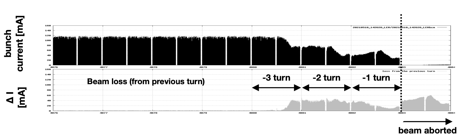
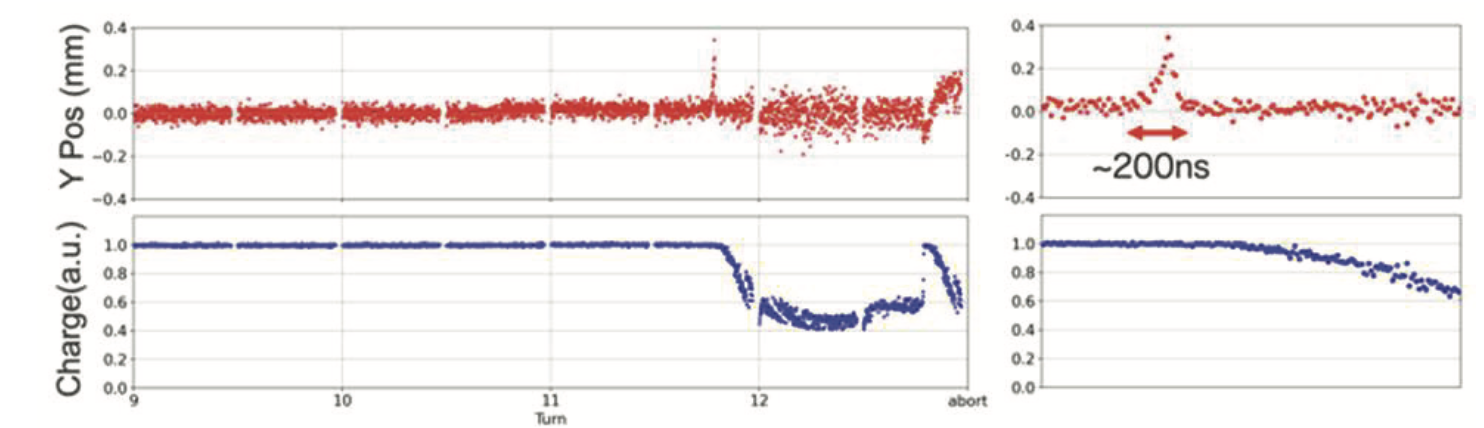
Currently, we are focused on collecting physics data while simultaneously working to improve the luminosity performance of SuperKEKB and maintaining the Belle II detector. In June 2020, SuperKEKB surpassed the instantaneous luminosity record of KEKB, officially becoming a leading luminosity frontier machine. However, simultaneously, mysterious beam losses began to be observed. This beam loss, referred to as Sudden Beam Loss (SBL), is troublesome because it causes the beam to lose most of its particles within a few beam-cycles, scattering a large amount of radiation within the ring, as shown in Figure 1. The figure shows the bunch current measured by the Bunch Current Monitor (BCM) [9].
This SBL phenomenon has caused damage to accelerator and detector equipment, such as the pixel detector in the innermost layers of the Belle II detector and beam collimators. Since the radiation dose is proportional to the beam current, we have had to be cautious about increasing the current, which has hindered the improvement of luminosity.
By 2021, it became commonly recognized that this beam loss was not a transient issue but had some fundamental cause behind it, making it an unavoidable problem when increasing luminosity. Since then, we have started developing an advanced beam diagnostic system to localize the start of the beam loss, as well as enhancing the beam abort system to mitigate its effects. Although we are still striving to elucidate the cause of the SBL phenomenon, this article introduces some of the research efforts detailed in the sections on our beam diagnostic system and beam abort system upgrades, aimed at finding clues to address this issue.
2 Overview of Key Accelerator Subsystems
Before detailing the beam diagnostic system and beam abort system enhancements, which are central to addressing the SBL issue, we will briefly introduce the accelerator subsystems that are crucial to this study, particularly the collimator system and the beam abort system.
2.1 Collimators
Beam particles deviating from the normal trajectory due to scattering with residual gas in the ring [10], interactions with particles within the bunch (Touschek effect [11]), beam injection oscillations, etc., eventually collide with the beam pipe and form secondary particle showers. These are observed as beam background [12] in the Belle II detector. Each subsystem defines acceptable background levels, and shifters and experts carefully monitor the background during operation. High background levels increase trigger rates, destabilize the data acquisition (DAQ) system, and degrade the quality of physics data.
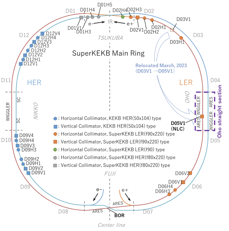
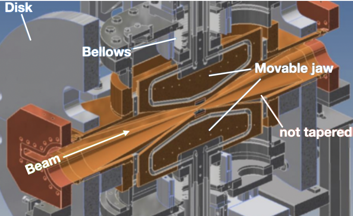
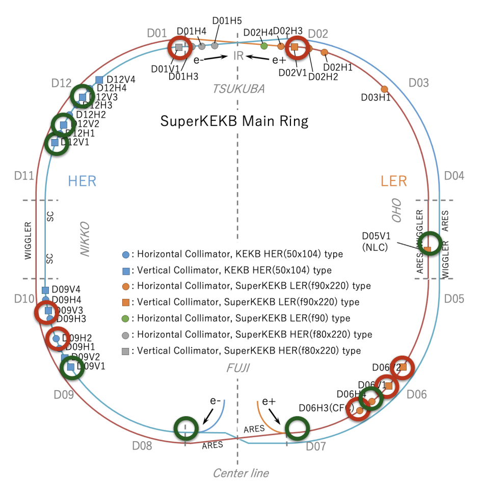
Here, collimators [13] come into play. SuperKEKB’s ring is equipped with movable collimators, which are one of the accelerator components (see Figure 3). The tungsten head 111In addition to tungsten, other metals such as tantalum and titanium, as well as carbon, are also used for collimator heads. The length and material of the head in the beam direction are selected according to the collimator position. attached to the movable part on the vacuum side is brought close to the beam orbit to scrape off as many deviated beam particles as possible before they reach the Belle II detector. Collimators are also essential for protecting the QCS from quenching. There are 31 horizontal and vertical collimators installed upstream of the collision points in both the electron ring (HER) and positron ring (LER), as shown in Figure 2.
Those used since the KEKB era are cantilevered collimators with heads on the top or bottom (inside or outside for horizontal collimators), but those newly installed for SuperKEKB are equipped with twin movable jaws, with independently operable jaws at the top and bottom. The apertures of each collimator are critical machine tuning parameters and must always be adjusted to optimal conditions. During operation, the apertures of each collimator are set to about 1 cm at the widest points and about 1 mm at the narrowest points, controlled with a precision of 50 m.
Adjustments are frequently made amidst constantly changing operational conditions. Opening the collimators too much increases background levels, while closing them too much disrupts beam injection and increases the frequency of beam aborts.
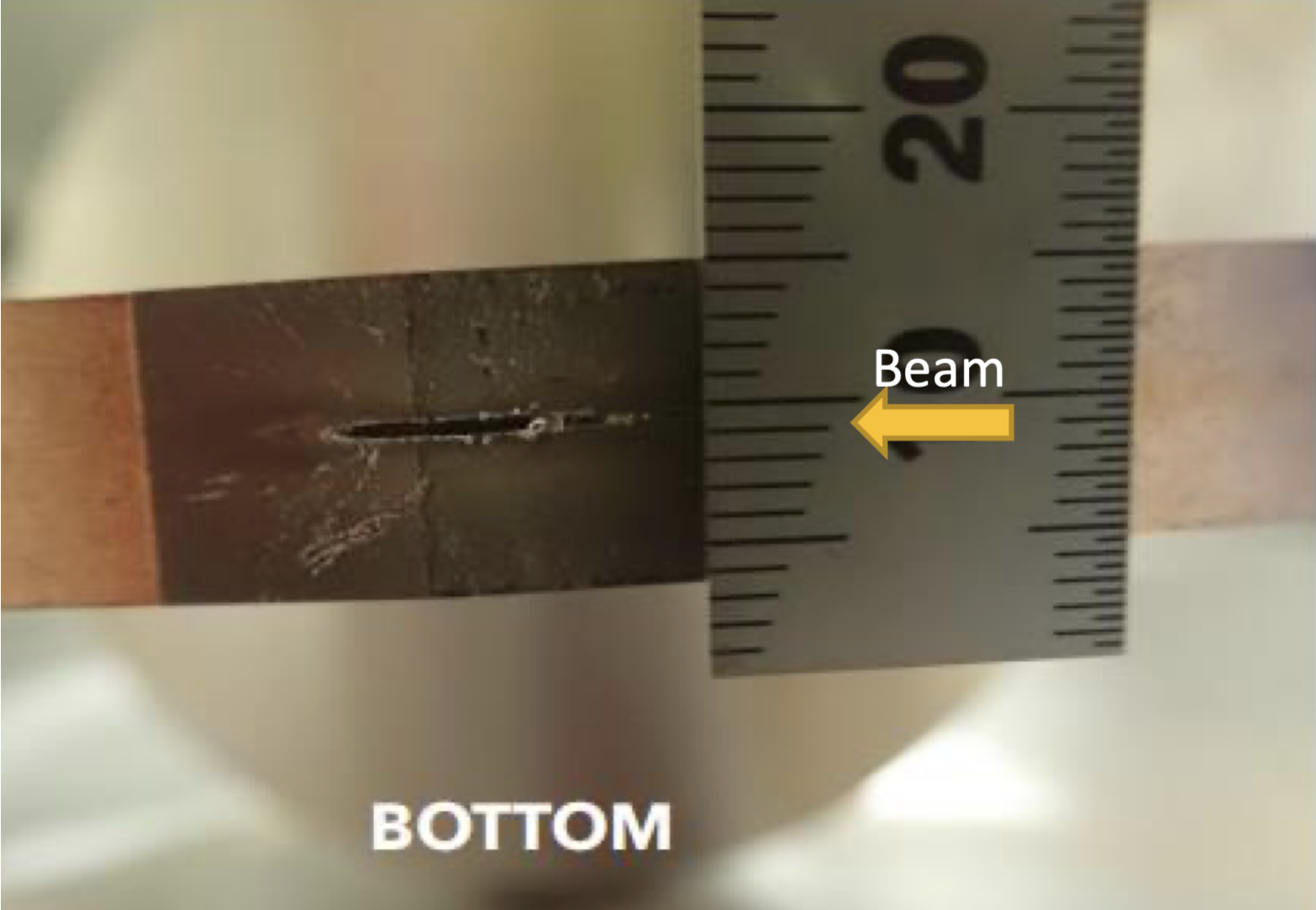
When a collimator is damaged by an SBL event (see Figure 4), the aperture has to be widened, making background control difficult. Although other collimators can be used as substitutes, if key collimators close to the Belle II detector, particularly vertical collimators, are damaged, there are no replacements. Depending on the extent of the damage, collimator heads may need to be replaced. However, this requires breaking the local vacuum, necessitating a vacuum bakeout 222Immediately after opening, the ring pressure rises, resulting in high background levels due to collisions between residual gas and the beam. Therefore, machine operations must be conducted without collisions for several days until the vacuum level sufficiently decreases.. It takes at least a week to return to the original operational condition. If a major collimator near the main ring injection point is damaged, the high radiation levels prevent immediate replacement. Waiting for radiation levels to decrease takes over a month, making replacement during the limited operation period impractical. Therefore, understanding the mechanism of the SBL phenomenon is essential to operate collimators without damage.
2.1.1 Nonlinear Collimator (NLC)
To mitigate the issue of collimator damage and improve beam stability, a novel collimation approach called the Nonlinear Collimator (NLC) [14, 15, 16] was introduced during the Long Shutdown 1 (LS1) period, which spanned from the fall of 2022 to the spring of 2024. The NLC was installed in place of the wiggler magnets in the D05 section. SuperKEKB is the first operational accelerator to adopt this NLC concept.
The principle of the NLC is to use the nonlinear magnetic field of a skew sextupole magnet to kick beam halo particles with large vertical orbit deviations, then remove these particles at a downstream vertical collimator. The NLC effectively mitigates beam halo without compromising the beam core, significantly reducing the impedance. This approach enhances the overall beam performance and stability, contributing to the reduction of beam background in the Belle II detector. Furthermore, by minimizing the risk of collimator damage, the NLC ensures more reliable operation and reduces the downtime associated with collimator replacements. This innovative collimation method represents a significant advancement in maintaining the integrity of collimators and optimizing the performance of the SuperKEKB accelerator.
2.2 Beam Abort System
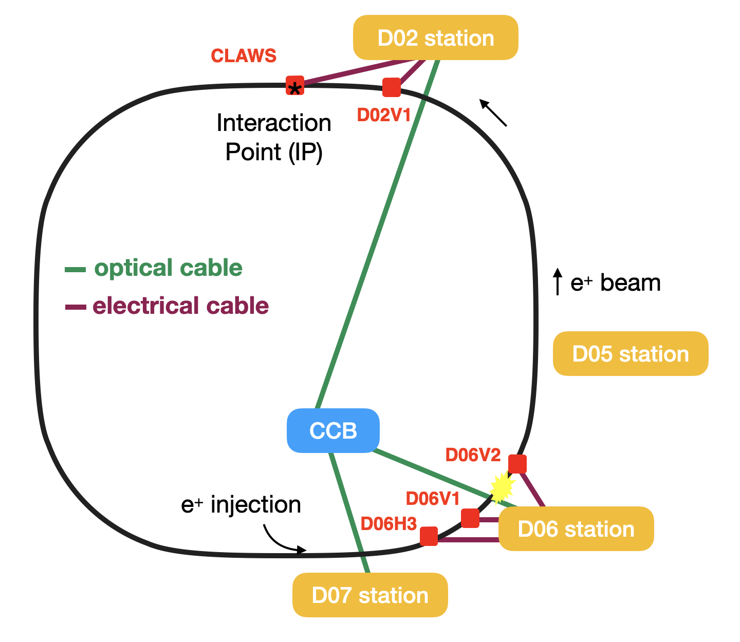
The beam abort system in SuperKEKB [17] is designed with both horizontal and vertical abort kicker magnets to safely and quickly dispose of the beam when anomalies are detected in the beam or accelerator equipment. The current system aggregates abort request signals from sensors installed around the ring via both optical fibers and electrical signal lines to the Central Control Building (CCB), which then transfers trigger signals to the abort kicker magnets. When the signal is received, the horizontal kicker magnet extracts the circulating beam, which is then deflected by the Lambertoson DC septum magnet towards the beam dump. The vertical kicker magnet protects the extraction window by tapering the beam trajectory, effectively enlarging the beam cross-section at the window.
SuperKEKB’s beam consists of two bunch trains, with a gap (abort gap) of about 200 ns between them. This gap is set considering the rise time of the kicker magnets, and during an actual beam abort, trigger signals are sent at this abort gap timing to correctly apply the magnetic field to deflect the beam toward the beam dump. The time from anomaly detection to beam dump depends on the position of the sensor detecting the loss and the relationship between the lost bunch and the abort gap, but it is generally around 20 to 30 s.
SuperKEKB uses various devices as abort sensors, including PIN photodiodes (PIN PD) [18], ion chambers [18], optical fibers, diamonds sensors [19], and CLAWS (plastic scintillators read out by SiPMs) [20]. Below, we provide additional details on some of these sensors:
2.2.1 PIN PDs and Optical Fibers
PIN PDs and optical fibers are installed in locations such as near collimators, where beam losses are likely to be observed because of their narrow aperture in the ring. They are used not only for beam aborts but also for real-time beam loss monitoring. These sensors are crucial for detecting and responding to SBLs.
2.2.2 Ion Chambers
Ion chambers focus primarily on beam aborts. Each ion chamber covers several meters and is widely installed around the ring. They provide a broad detection range and are integral to the overall safety and functionality of the beam abort system.
2.2.3 Diamond Sensors
Diamond sensors, specifically single-crystal Chemical Vapor Deposition (sCVD) diamonds, are used as beam loss monitors at SuperKEKB. They are mounted on the beam pipe, SVD support cones, and QCS bellows. Diamond sensors function as solid-state ionization chambers. When high-energy particles pass through, they create electron-hole pairs, generating a current proportional to the radiation dose. This current is processed by dedicated electronics, including trans-impedance amplifiers and high-speed ADCs. The diamond sensors provide comprehensive coverage of the IP region. They deliver real-time data for monitoring and beam abort triggers, protecting the Belle II detector from radiation damage. Their performance has been validated during the commissioning phases of SuperKEKB and Belle II, proving their reliability and effectiveness in beam loss monitoring.
2.2.4 CLAWS Detectors
The sCintillation Light And Waveform Sensors (CLAWS) system was introduced in 2016 during the SuperKEKB commissioning to monitor beam-induced backgrounds, initially focusing on injection-induced backgrounds. Each CLAWS module uses plastic scintillators coupled with silicon photomultipliers (SiPMs) to detect and measure beam losses. The system comprises 32 modules, strategically placed around the IP Region, with 16 modules on the forward side and 16 on the backward side. These modules are positioned at four different longitudinal locations along the beam direction, approximately 1, 2, 3, and 4 meters from the IP, and at four different azimuthal angles (0, 90, 180, and 270). Initially designed for monitoring injection-induced backgrounds, CLAWS shifted its role to an abort sensor after 2020 as injection backgrounds decreased. Its rapid response compared to other abort sensors has proven valuable in detecting beam losses early. CLAWS now provides real-time data on beam losses, helping to prevent potential damage and ensure stable operation, and its early detection capability has been effectively integrated into the current beam abort system [21, 22, 23].
3 High-speed Beam Diagnostic System
To better understand beam losses, it is crucial to determine where in the ring the beam losses begin. The existing loss monitors, specifically PIN photodiodes, are engineered to accommodate a broad dynamic range and adhere to the specifications required by the readout electronics. Consequently, these monitors exhibit prolonged integration and response times, limiting the measurement accuracy of beam loss timing to approximately 2-3 s. This temporal resolution is inadequate for precisely identifying the initiation points of beam losses, thereby necessitating the deployment of high-speed beam loss monitors.
Loss monitors are strategically placed near collimators, as these locations represent the smallest physical apertures in the ring and are thus more prone to beam losses. Therefore, both the current PIN PDs and the newly developed loss monitors are predominantly installed in proximity to the collimators. Given that the collimator intervals range from a few tens of meters to several hundred meters, a time resolution of approximately 30 ns for these high-speed loss monitors is sufficient, obviating the need for exceptionally fast detectors.
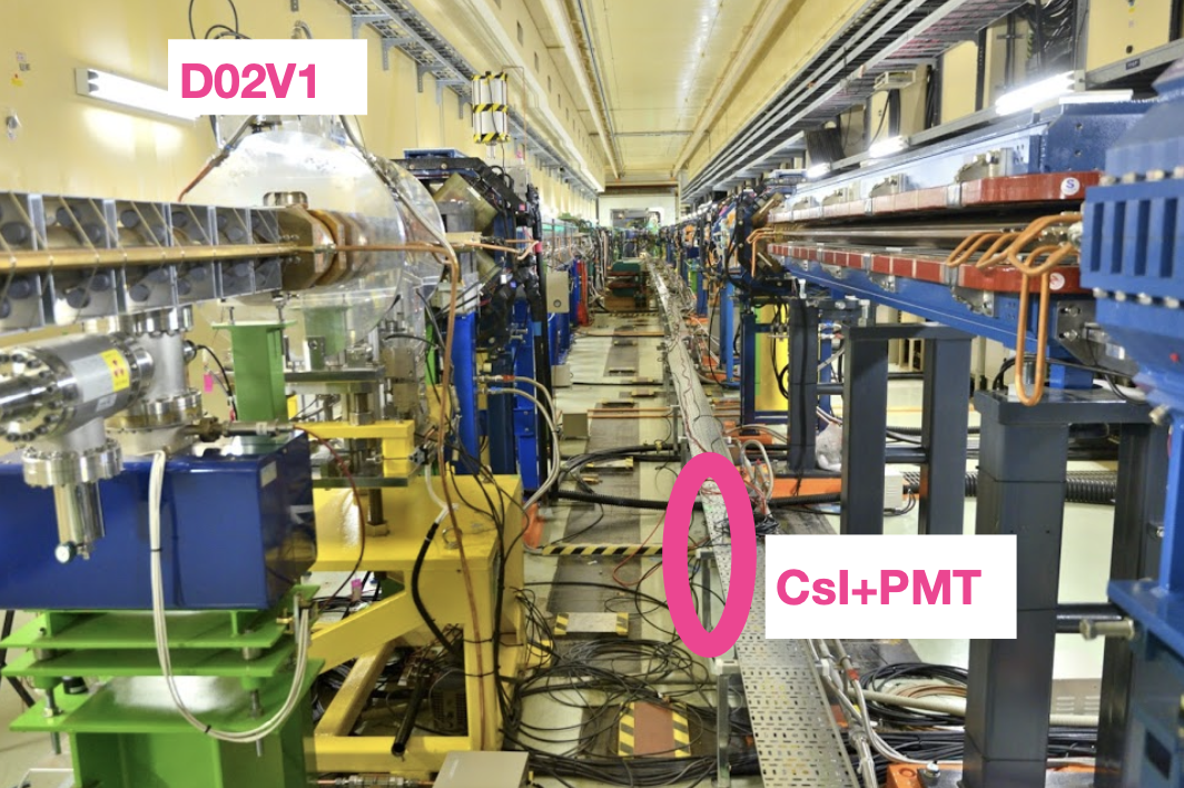
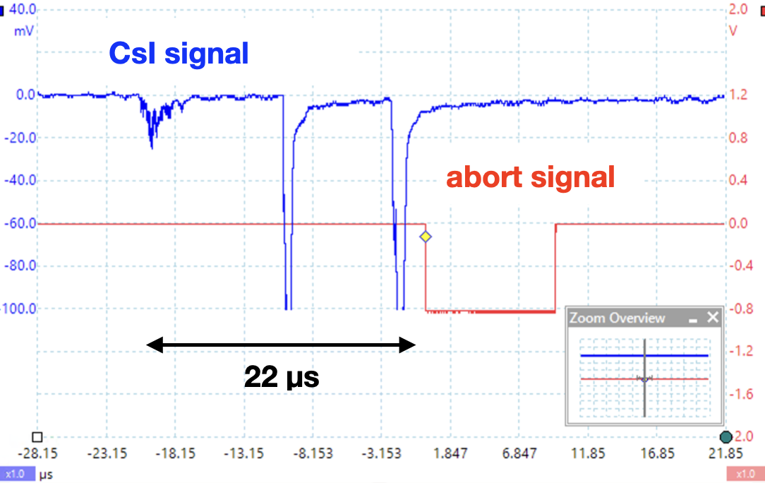
To demonstrate the rapid detection of beam loss, a PMT coupled with a CsI crystal was installed near the vertical collimator in LER, which is the closest to the Belle II detector. This setup successfully recorded clear beam loss signals (see Figure5). Analysis revealed that beam losses started two beam-cycles prior to the abort333One beam-cycle corresponds to approximately 10 s.. By increasing the number of loss monitors and conducting synchronized measurements across the monitors, it will be possible to determine the initial detection point of the beam loss. This integration of multiple loss monitors with a time synchronization system constitutes the high-speed beam diagnostic system.
3.1 High-speed Loss Monitors
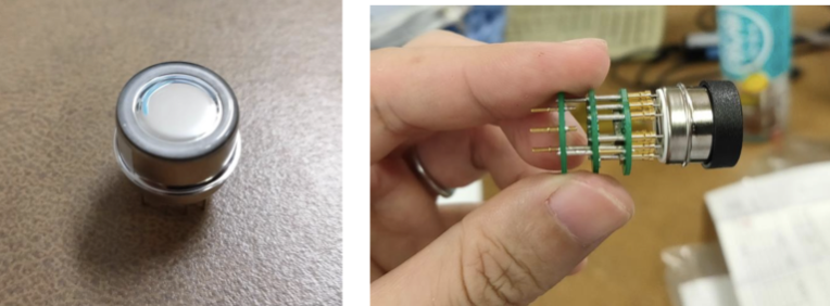
In addition to the PMT with a CsI crystal introduced earlier, an Electron Multiplier Tube (EMT) was adopted as a loss monitor (see Figure 6). The former has a time constant of about 20 ns, meeting our required time accuracy. The latter was originally developed and considered for use as a muon beam monitor in the T2K experiment [24]. Although the dynode structure is the same as that of a general PMT, the photocathode is replaced with an aluminum film, making it less sensitive to photons but more radiation-resistant than commonly used SiPMs.
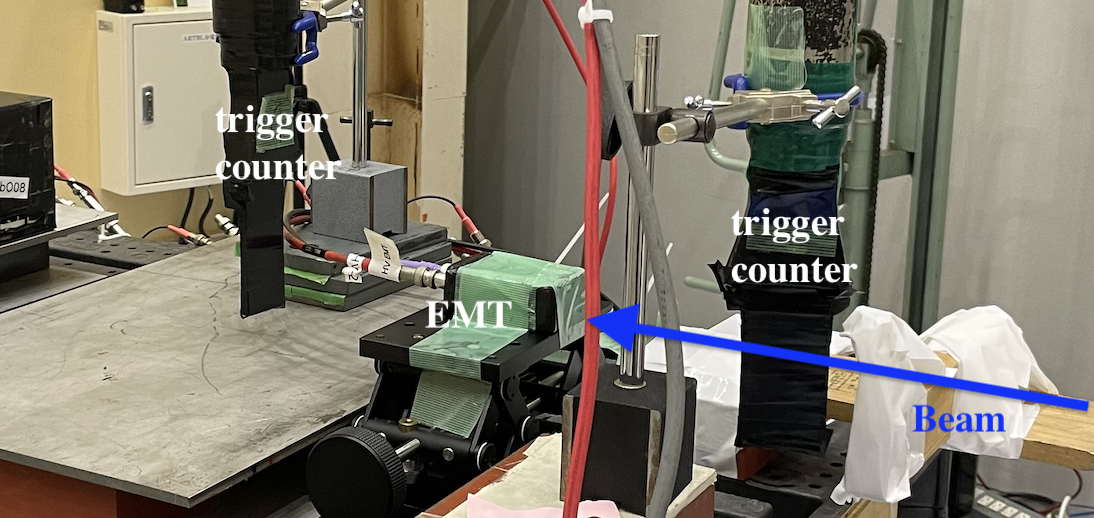
The performance of EMT was evaluated using a Sr-90 beta source and electron beams at the newly established test beam line at KEK’s PF-AR facility. During the beam tests, triggers were created with counters placed before and after the EMT, as shown in Figure7, and basic characteristics such as detection efficiency were evaluated.
It was confirmed that the EMT signal pulse width was short, about 10 ns, meeting the required precision. The detection efficiency was measured by varying the electron beam energy within the range of 1-5 GeV, and it was determined to be approximately 0.5%. This efficiency implies that for a bunch current of 0.5 mA with an acceptance of 0.1%, the system can detect the loss of a single bunch.
3.2 System Configuration
During machine operation, the entire tunnel experiences high radiation levels, especially the upstream part of the ring near the beam injection point, due to significant beam loss associated with the injection process. Therefore, EMTs, which possess high radiation tolerance, were installed in the upstream section near the injection point, while CsI+PMTs were installed downstream near the Belle II detector. Due to the potential lack of radiation tolerance of the data acquisition system, it was placed in the nearest power station, with long signal and power cables, approximately 100-300 m in length, running through the tunnel. To date, 15 loss monitors have been installed primarily around the key collimators in both the LER and HER rings, as shown in Figure 8 and detailed in Table 1.
| LM Type | Ring | Position |
|---|---|---|
| EMT | LER |
D06H3, D06H4,
Injection Point |
| CsI+PMT | LER |
D06V1, D06V2,
D05V1, D02V1 |
| EMT | HER |
D09H2, D09V1,
D09V3, Injection Point |
| CsI+PMT | HER |
D12V1, D12V2,
D12V3, D01V1 |
3.3 Time Synchronization System
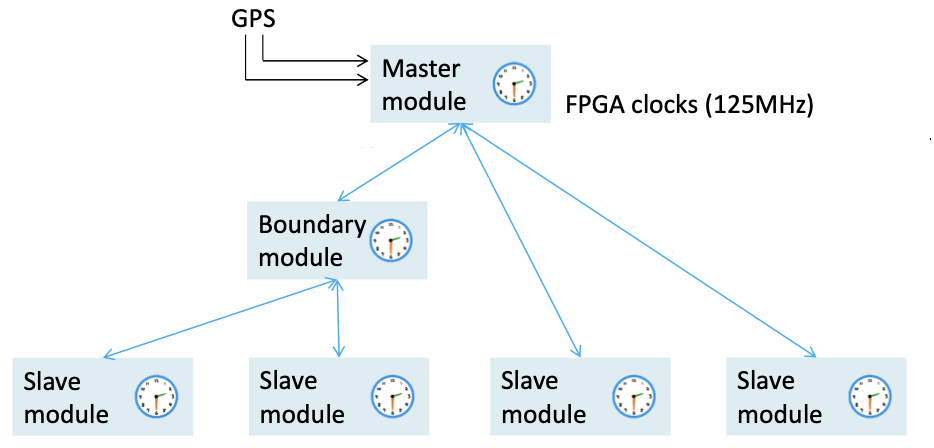
To compare the relative time differences between loss monitors, we adopted the White Rabbit (WR) high-precision time synchronization system [25]. WR achieves sub-nanosecond time synchronization by synchronizing the internal clocks (e.g., CPU time) of different WR nodes connected via optical cables 444Direct attach cables connected to SFPs are also acceptable. in three stages: sub-microsecond time synchronization via the Precision Time Protocol (PTP), internal clock synchronization via Synchronous Ethernet (Sync-E), and identifying and correcting phase differences between synchronized clocks via digital dual mixer time difference. Originally developed primarily by CERN, the WR standard is fully open-source on the Open Hardware Repository (OHR), and its implementation is progressing in various physical experiments. WR nodes are categorized as either Master or Slave and are connected by single-mode optical fibers, allowing for the sharing of timestamps between nodes. Although the nodes can be connected with optical fibers up to 80 km in length, boundary modules facilitate daisy-chain connections, enabling time synchronization between nodes at even more distant locations, as depicted in Figure 9. This system is ideal for timing control in large accelerator facilities, including SuperKEKB. The WR-TDC 555WR can also be used as a TDC or ADC, depending on the FMC card installed. we utilize operates with a 125 MHz clock, achieving a time resolution of 8 ns, which sufficiently meets our precision requirements.
3.4 Data Acquisition System
In addition to WR-TDC, we use a USB oscilloscope (Picoscope 3403D) to acquire data from the loss monitors. The oscilloscope captures waveform data 1 ms before and after the abort signal (corresponding to approximately 100 beam-cycles before and after), allowing time-series analysis of beam losses. As shown in Figure 10, loss monitor signals are split into two at the nearest power station, with one path connected to the oscilloscope and the other to the WR-TDC.
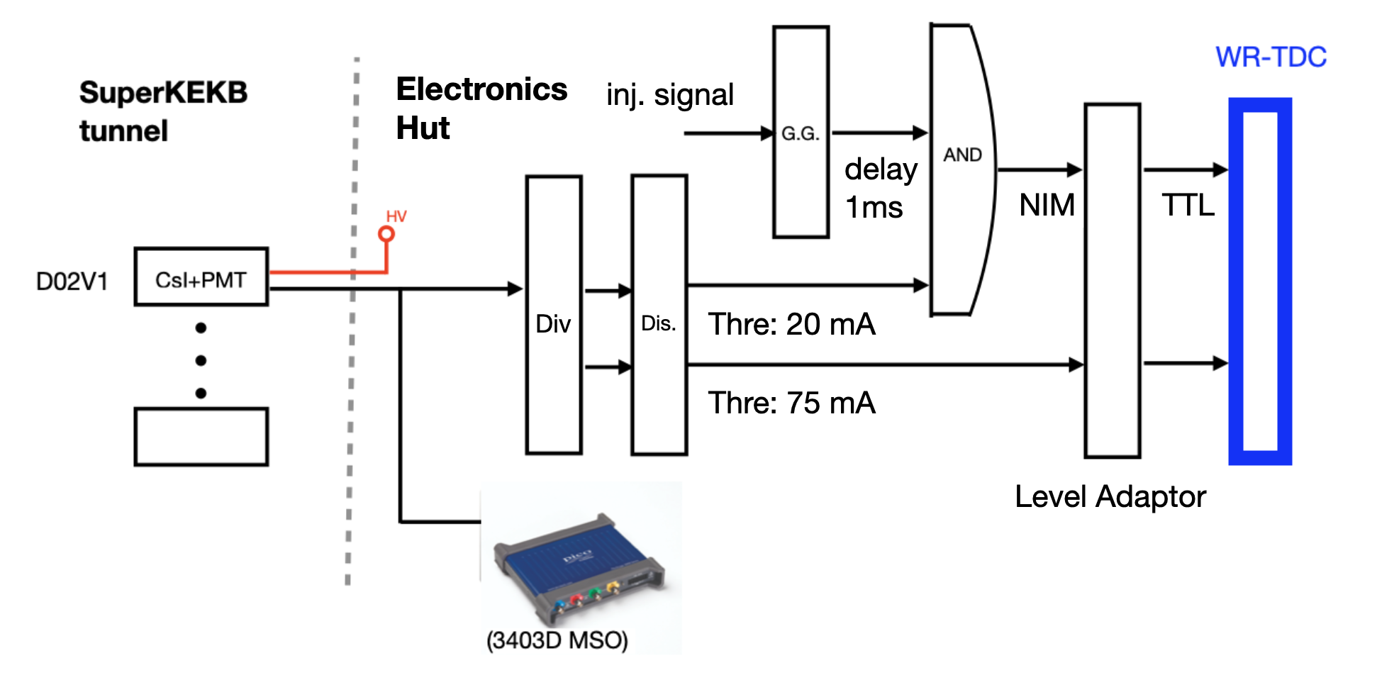
The loss monitors can observe not only SBL events but also injection losses arising from the horizontal beam oscillations during the beam injection. Therefore, the signal line on the WR side is further split to obtain data for beam injection studies, in addition to SBL events. For SBL-targeted signals, the threshold is set to the minimum, and an injection veto is applied to the WR-TDC until the injection oscillations settle.
4 Beam Loss Analysis
4.1 Timing Calibration for SBL Analysis
To accurately analyze beam losses and SBL events, precise timing calibration of the detection system is crucial. The WR system provides accurate time synchronization by sharing timestamps between nodes, eliminating the need for special corrections. The WR-TDC and Picoscope timing were further calibrated using cable length corrections. The cable lengths were measured using a spectrum analyzer by observing the signal reflection peaks at connector positions.
For SBL analysis, the beam abort signal is used as the time reference. The master WR node, located in the central control building (CCB), is directly connected to the abort module and thus inherently knows the exact time the abort signal is issued. However, for the Picoscope, corrections are necessary to account for the time delay of the abort signal reaching each power station where the loss monitor DAQ systems are installed. This ensures accurate determination of which loss monitor first detected the beam loss by comparing the timestamps from the different monitors.
4.2 Injection Analysis
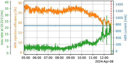
As the beam is further squeezed in the future, it becomes essential to maintain or even improve the beam injection performance to accumulate beam current and enhance luminosity. This is particularly critical in HER, which has lower injection efficiency compared to LER. The high-speed loss monitors play a vital role in achieving this objective by providing real-time data that helps in optimizing beam injection performance. Additionally, the loss rate is displayed live in the accelerator control room, assisting in diagnosing issues with the collimators.
We analyzed the beam losses occurring during beam injection. Figure 11 illustrates the correlation between the beam loss rate observed by the high-speed loss monitor installed near one of the HER collimators and the injection efficiency of HER under constant beam current conditions. The data shows that the loss rate increases as the injection efficiency decreases. This correlation is continuously monitored across all loss monitors, aiding in the tuning of injection parameters.
4.3 SBL Analysis
4.3.1 Pre-LS1 (2022 Analysis)
We analyzed the SBL events observed during the 2022 operation. Although SBL events occur in both LER and HER, they are more frequent in LER, so the analysis focused on SBL events in LER. Using the beam abort signal timing 666This is the timing when the abort trigger module in the CCB receives an abort request from the abort sensor and issues an abort signal. as a reference, we investigated which loss monitor first detected the beam loss. It was found that beam losses were often first detected at D06V1 or D06V2, located upstream in the ring and closer to the injection point than the collision point, as shown in Figure 12.
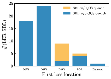
It was also found that when the first loss was detected at D02V1, which is close to the Belle II detector, the probability of QCS quench was high. It is conceivable that the beam trajectory was disturbed upstream of D06V1, resulting in beam loss near the D06V1 collimator, and the generated shower was observed by the loss monitor. The increased number of SBL events at D06V2 was likely due to damage to D06V1 during machine operation, leading to the widening of the collimator aperture and thus increasing the number of events passing through D06V1 and hitting D06V2. Additionally, despite beam losses being observed upstream, the first abort request was often issued not by the abort sensors placed at D06V1 or D06V2 but by CLAWS placed near the Belle II detector 777Abort requests are issued from various locations around the ring, but the first signal to reach the CCB and trigger the abort is from CLAWS..
4.3.2 Post-LS1 (2024 Analysis)
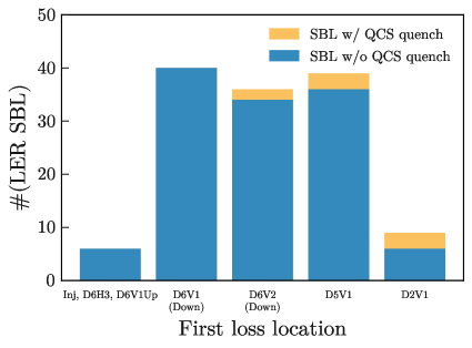
During the LS1 period, three loss monitors were added to LER and five to HER, allowing for full-scale beam diagnostics. This significant enhancement has enabled more precise monitoring and analysis of beam losses. In the 2024 analysis, 132 SBL events were observed in the LER and 19 in the HER, providing a substantial dataset for investigation (see Figure 13). Initially, beam losses were frequently detected first at D06V2 and D05V1, where the NLC collimator was installed during LS1. Over time, there was a noticeable shift, with an increasing number of losses being detected first at D06V1. This shift is likely influenced by the aperture settings of each collimator.
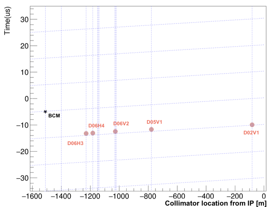
SBL events caused by the misfire of a thyratron switch in the injection kicker magnet were also analyzed. In these cases, losses were predominantly first detected at D06H3. This can be explained by the horizontally kicked bunches colliding with the D06H3 collimator, with the resulting shower observed by the loss monitor located just downstream of the collimator, as shown in Figure 14). The figure shows that the loss times and positions at each loss monitor are well-aligned in a two-dimensional plane, confirming that the time calibration is functioning correctly.
Additionally, there is a notable correlation between SBL frequency and beam current; higher beam currents are associated with more frequent SBL events. Furthermore, a large number of LER SBL events were found to correlate with pressure bursts exceeding Pa, with pressure changes surpassing 20% per second, at specific locations within the ring, particularly downstream of the D10 and D4 sections. The first loss location strongly correlates with the IR dose. For SBLs with the first loss occurring at D2V1, the average IR dose is 849 mRad. In contrast, for SBLs with the first loss occurring at D6V1, the average IR dose is only 45 mRad. This difference is reasonable as the collimators between D6V1 and the IR can mitigate the loss in the IR region.
In the HER, SBL events were primarily first detected by loss monitors installed in the D09 section, such as D09V1 and D09V3. However, no significant correlation has been observed between these losses and pressure bursts or other potential indicators. Continued investigation and analyses are crucial to better understand the mechanisms driving these SBL events in the HER.
4.4 Mechanism of SBL
Despite gaining insights into the locations of beam losses through the beam diagnostic system, the fundamental causes of SBL events remain elusive. Previously, similar mysterious beam losses have been observed and reported in other accelerators. For instance, at SLAC’s PEP-II, rapid beam losses due to vacuum breakdown were eventually identified as being caused by damaged tiles that absorbed higher-order harmonics excited by passing bunches, following an extensive investigation [26]. Similarly, at CERN’s LHC, beam losses attributed to Unidentified Falling Objects (UFOs) are currently under investigation [27].
At SuperKEKB, several hypotheses have been proposed to explain the occurrence of SBL events. One prominent theory involves beam-dust interactions, where dust particles generated from damaged components such as clearing electrodes fall into the beam path, leading to interactions that result in beam losses [6, 28, 29]. This hypothesis is supported by the observed correlation between SBL events and pressure bursts in specific sections of the accelerator, particularly those influenced by synchrotron radiation.
Another hypothesis is the fireball hypothesis, which suggests that high-temperature microparticles, potentially originating from damaged collimators, might become heated by the beam’s electromagnetic fields [30]. These particles could then float within the beam pipe, eventually striking the surface and creating a plasma that interacts with the beam, leading to rapid losses. This hypothesis aligns with the rapid timescales observed during SBL events and is supported by the materials involved, which are consistent with those found in collimators and beam pipes.
5 Acoustic sensors
Regardless of whether the cause of SBL is beam-dust interaction or fireballs, the generated microparticles interact with the beam, causing discharges. Detecting these discharges would provide conclusive evidence for the cause of SBL. Observing discharges can be achieved by detecting high-frequency signals or direct observation of particle emissions, but this is challenging near collimators.
Since it has been known that the discharge happening in an RF cavity can be identified by the ultrasonic wave signal [31], we attempted to detect discharge phenomena at beam aborts by attaching acoustic emission (AE) sensors. These sensors measure sound waves generated by the thermal shock of discharge currents impacting metal surfaces, in the ultrasonic range to avoid environmental noise. Acoustic sensors act as “new ears” to complement the “new eyes” of the high-speed loss monitors. Initial evaluations of sensor performance and adhesives, optimization of sensor positions and numbers using spare collimators, and observation of acoustic signals during vacuum discharges in RF cavities have been conducted.
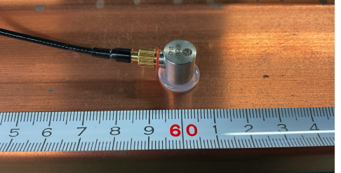
A total of 34 AE sensors, developed by MATEX KENZAI CORPORATION (Model number: AE124-AT), were used. The sensor can receive a voltage from the piezoelectric element when applied to inertial force, and its size is 1 cm 1 cm. It can detect vibrations in a high frequency range from 10 kHz to 1 MHz, which is suitable for our purpose. Figure 15 shows an AE sensor. These sensors were installed around the collimators and QCS in the SuperKEKB tunnel, specifically at D02V1, D05V1, D06V1, D06V2, and QCS-R.
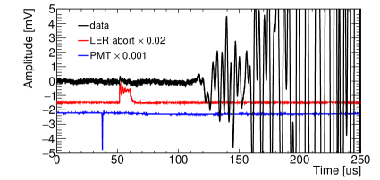
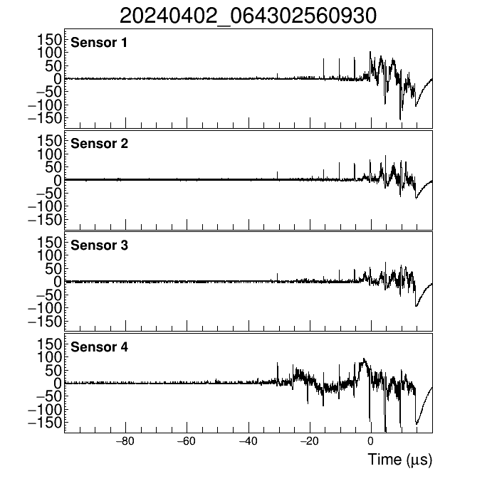
Sound waves have been measured with the AE sensors since the start of operations in 2024. A typical AE sensor signal is shown in Figure 16, where the readout oscilloscope is triggered by the beam abort signal. This indicates that the ultrasonic wave signal is detected when the beam loss occurs, and there is a relevant electromagnetic shower passage at the accelerator component equipped with AE sensors, confirming the basic functionality of this method. Near the acoustic sensors, a high-speed loss monitor explained in Section 3.1 was installed.
If a discharge inside a vacuum chamber causes beam loss, the loss monitor signal is expected to be preceded by the AE signal, but no such events have been found. Therefore, the fireball hypothesis is disfavored as the cause of SBL, but its possibility cannot be entirely ruled out. Further investigation near upstream collimators is necessary. On the other hand, the AE sensor is established as a new method to detect beam loss. This allows inactive materials such as vacuum chambers and collimators to be turned into active devices for detecting beam loss.
6 Beam Abort Upgrade
In the development of the loss monitor system and during the operation of SuperKEKB, it became evident that speeding up the beam abort to minimize damage caused by beam losses is as important as understanding SBL. As shown in Figure 12, the D06 power station is geographically closer to the central control building (CCB) and abort kicker magnets than the collision point where the CLAWS system was initially installed, near the interaction region (IR). However, the first abort request was issued by CLAWS. This observation led to the crucial insight that if the first abort request could be issued from sensors placed at D06 instead of CLAWS in IR, the abort could be significantly sped up.
To verify this effect, we used the loss monitor installed at D06V1 to output a pseudo-abort request and compared it with the abort request issued by CLAWS during the last period of beam operation in 2022. We demonstrated that an improvement of up to 10 s was possible. An improvement of 10 s corresponds to approximately one beam-cycle, which would reduce beam losses in the ring by about 20% in the example shown in Figure 1. For some SBL events, even greater improvements can be expected. Based on this promising result, we decided to install additional CLAWS in the upstream regions of the ring, specifically around the vertical collimators in the D05 and D06 areas.
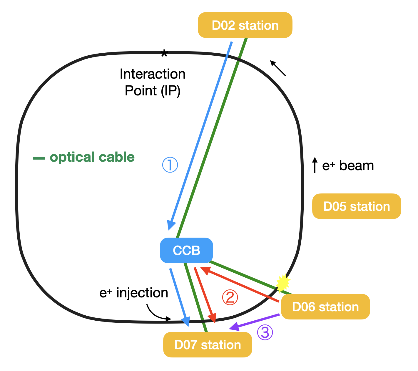
Furthermore, as shown in Figure 17, if the abort request signal can be sent directly from the D06 power station to the D07 power station where the abort kicker pulse power supply is located, bypassing the CCB, even greater improvements can be expected. Additionally, replacing optical fiber communication with laser communication for signal transmission between power stations would enable further speedups. Currently, we are working on expanding the abort modules to the D07 power station and developing laser transport R&D with this ambitious goal in mind.
6.1 Additional CLAWS Installation at D05
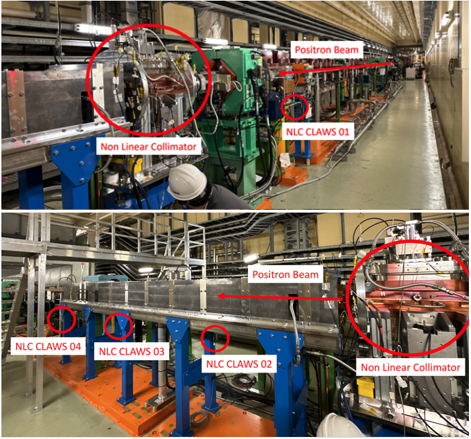
After careful consideration of factors such as reducing cable lengths and the strategy to utilize the newly constructed NLC collimator at D05 more actively for background reduction while minimizing collimator damage risks after LS1, this collimator was selected as the first location for the additional CLAWS installation. Consequently, four CLAWS sensors were installed around the D05V1 collimator as shown in Figure 18. One sensor was positioned upstream of the collimator, while the remaining three were placed downstream.
During the operations in early 2024, the commissioning of the new CLAWS sensors was conducted. Figure 19 illustrates a typical signal during a beam abort.
Sensors #1 (upstream) and #4 (most downstream) generally observed larger beam losses. In the case of SBL events, the beam loss around this collimator was significant, causing saturation in all CLAWS sensors. Sensor #2 was selected as the abort sensor to ensure a broad threshold range for the abort request condition. Initially, the abort request threshold was set to 35 mV, which was later increased to 100 mV by the end of the 2024 spring run period.
In addition to the threshold, the signal pulse width (duration) was incorporated into the abort request condition to effectively distinguish SBLs from other beam losses or noise. Commissioning results indicated that significant beam losses during SBL events last more than 1 s. The abort request signal is triggered when the beam loss waveform exceeds a duration of 180 ns. An injection veto was also incorporated into the abort request logic of the CLAWS at D05. The launch of the abort request signal is vetoed for 1 ms after injection. This condition was optimized during the 2024 spring operation.
An integration study of CLAWS into the abort system was conducted using the above abort request conditions by providing pseudo-abort requests with the new CLAWS abort sensor and comparing its response time with that of the operational abort trigger system. Most of the time, the pseudo-abort request was faster than the operational abort trigger, depending on which sensor first launched the abort request. The test results clearly demonstrated the effectiveness of the new CLAWS sensor. During this commissioning period, only once did the pseudo-abort request launch alone, which could be considered an unnecessary abort request. However, given its very low frequency of once a week, it was deemed acceptable for beam operation and commissioning. After confirming the feasibility of the new CLAWS sensor, it was integrated as the abort sensor in the SuperKEKB LER by the end of March 2024.
Following the installation of the D05V1 CLAWS, a total of 168 SBL events were recorded in the LER during the 2024 spring operation 888The 168 SBL events include those that occurred during the physics run, when the Belle II DAQ was operational, as well as during machine studies.. In 148 of these instances, the D05V1 CLAWS generated the fastest abort request signal. Preliminary analyses suggest that the CLAWS abort request was issued 5-10 s earlier than the second-fastest abort source. This improvement is anticipated to significantly mitigate beam loss and reduce potential damage to the IR components. Given the successful performance of the D05V1 CLAWS, the decision has been made to install additional CLAWS units around the D06V1 collimator during the 2024 summer shutdown.
6.2 Expansion of Abort Modules
To further speed up the abort response by optimizing the abort request signal path, the second master module of the abort trigger system was installed at the D07 power station during LS1. A direct optical line now connects D05 to D07, where the abort kicker power supply is located. With the master module installed at D07, it is possible to issue abort requests through this signal line without routing through the CCB. This modification changes the path from (2) to (3) in Figure 17. In this configuration, the response time of the abort system is expected to be shortened by 1.4 s for D05 and 1.9 s for D06, respectively. In practice, the operation timing of the abort kicker magnet is synchronized with the abort gap and quantized at 5 s intervals, so there is a 15% (D05) and 20% (D06) chance that the beam abort will be executed 5 s faster.
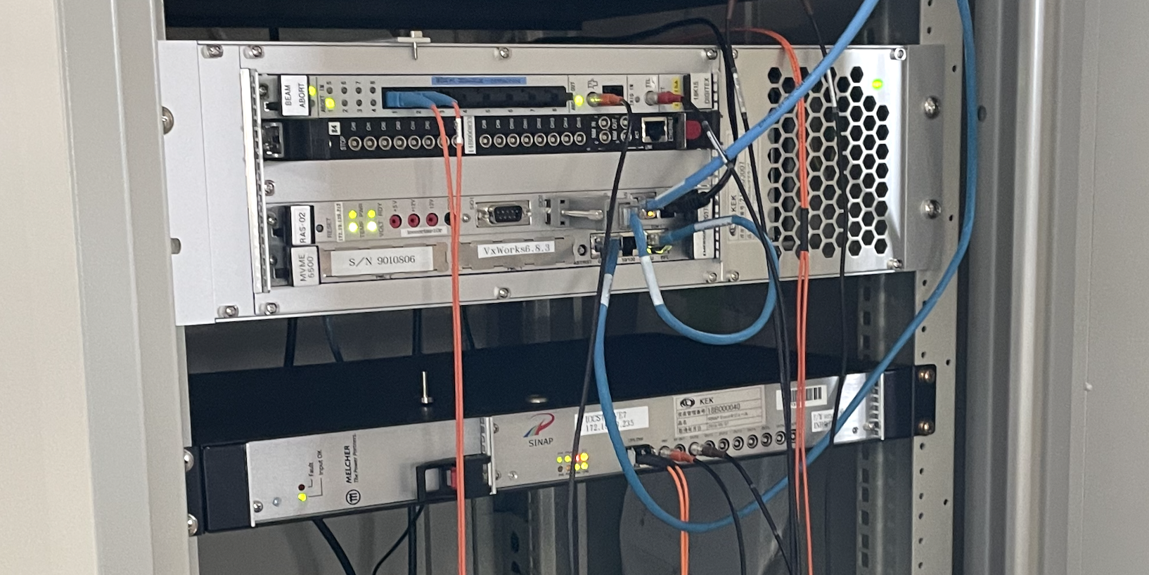
Figure 20 shows the second abort trigger system. This system is equipped with the same functions as the master module and abort kicker magnet trigger circuit currently installed in the CCB. The master module is a device that aggregates abort request signals from the slave modules at each power station and outputs trigger signals to the abort kicker magnet trigger circuit. The master module uses the VME-type platform circuit board. The abort request signals input to the second master module are issued by the slave module (2ch abort optical output circuits [32]) installed at the D05 power station, and it is connected to the newly installed CLAWS sensors.
The abort kicker magnet trigger signal is derived from a doubled signal of the accelerator’s beam-cycle signal, which corresponds to one beam-cycle period, and is delayed in synchronization with the abort gap. The Event Timing System module, newly installed at the D07 power station, functions as the output circuit for the turn signal, with one of its output terminals designated as the abort kicker magnet trigger. The abort request signal from the test master module is fed into the INHIBIT input terminal of the Event Timing System module, enabling precise control of the kicker trigger output.
This setup allows us to verify the speedup of the abort response by combining “early detection of SBL in D05” and “shortening the abort request signal path.” The verification test of this system commenced with the 2024 operation of SuperKEKB. Measurements were conducted over three days using the CLAWS installed at D05V1. For 14 abort events where the CLAWS at D05V1 issued the abort signal, it was confirmed in two cases that the beam abort was executed 5 s faster when bypassing the CCB compared to when it was routed through it. This result validates the expected improvement in response time. Additionally, the abort system is expected to serve as a test environment for the laser abort system development described in the next section.
As a further improvement, plans are being developed to bypass the D05 power station and directly connect the CLAWS signal to the abort master module at D07. This adjustment will reduce the signal transmission path to 700 m and the corresponding signal transfer time to 3.5 s. For comparison, the signal transfer time from the D05 power station to the D07 power station via the CCB is 6.1 s 999The CLAWS installed at D05V1 is approximately 100 m away from the D05 power station. The signal transfer time within this 100 m distance is ignored in this estimation.. This modification is expected to reduce the response time by at least 2.6 s.
The situation is expected to improve further with the planned installation of CLAWS near the D06V1 collimator in summer 2024. The signal transfer time to the D07 power station will be reduced to 1.5 s. Additionally, D06V1 is located approximately 400 m upstream of D05V1, which enhances the early detection of SBL events. While signal attenuation over this distance was initially a concern, tests have shown that the signal retains 10% of its original amplitude after transferring 700 m through the CLAWS cable. This level of attenuation is considered acceptable, given the substantial beam loss signal associated with SBL events.
6.3 Laser Abort System
Studies have been conducted to explore the use of lasers as a new transfer technology for abort request signals. In the current system, the abort request signal is transmitted using light with a wavelength of 820 nm. The master-slave modules of the abort trigger system operate on a negative logic specification: they constantly transmit light during normal operation (no abnormalities), and the cessation of this light transmission is interpreted as an abort request signal. This simple yet robust technology has inspired further research into laser-based transmission methods.
Using a highly directional laser instead of optical fiber to transmit the light signal allows for faster transmission due to the lower refractive index of air. Light can travel 1.5 times faster in air (refractive index of about 1) than in quartz, which is commonly used in optical fibers (refractive index of about 1.5). The transmission time difference between using optical fiber and laser to send light from the D05 and D06 areas of the accelerator tunnel to the D07 area is about 0.7 s and 0.9 s, respectively. This research also looks ahead to next-generation collider experiments, which may feature even longer beamlines than SuperKEKB, making reduced transmission time even more beneficial. Figure 21 shows a conceptual diagram of the laser abort request signal system. The signal from abort sensors, such as CLAWS, is used to control the power supply of a diode laser, enabling the laser to be toggled ON and OFF. The transmitted laser light is then focused into an optical fiber using a focusing lens positioned near the abort master module, where it is subsequently inputted into the module.
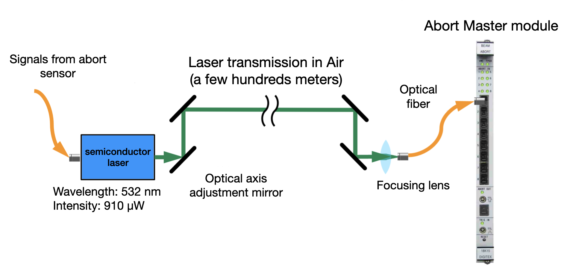
A class II green laser with a wavelength of 532 nm was selected as the signal source for several key reasons. Firstly, the abort trigger module is highly responsive to light in the green wavelength range. Secondly, successful operation of the abort master module, with a laser input power of 30 W, has been demonstrated through controlled laser activation. Additionally, the use of visible laser light simplifies the maintenance of the optical path. Finally, there are no regulatory restrictions on the operation of class II lasers, further supporting their suitability for this application.
The technology to efficiently focus the transported laser into the fiber has been well established [33], achieving a light collection efficiency exceeding 90%, while only 3% efficiency is required to collect the 30 W light necessary for operation. The collection efficiency has been measured relative to the laser diameters for various types of optical fibers, each with different core diameters and numerical apertures (See Figure 22). By selecting the appropriate optical fiber, such as one with a large core diameter or a high numerical aperture, the input requirements for the abort master module can be reliably met.
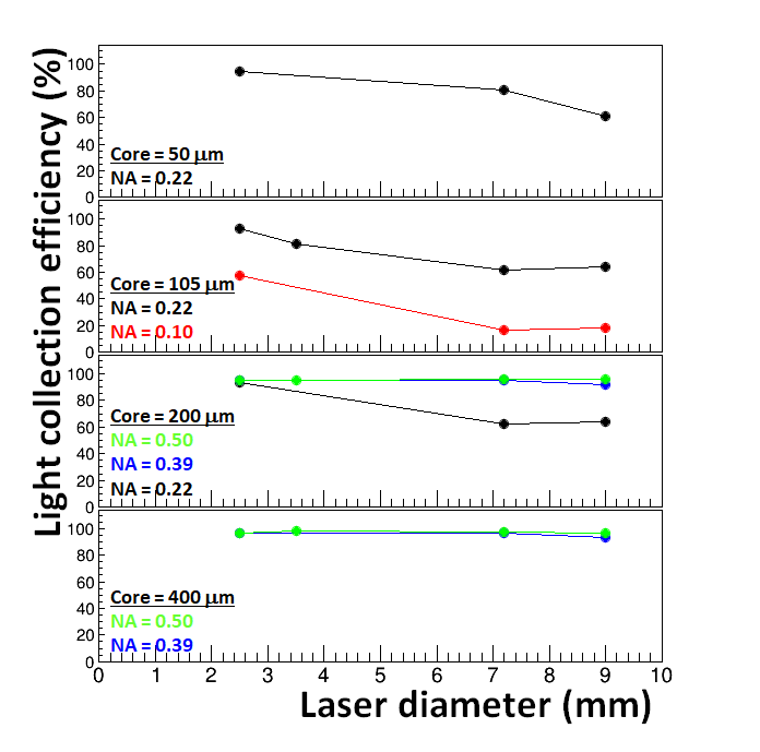
Another crucial aspect of the laser abort signal system is the optical technology required to maintain the laser beam profile during long-distance transmission. Typically, the beam size broadens over long distances due to imperfect beam collimation and light scattering by air molecules. As shown in Figure 22, there is a noticeable decrease in efficiency as the laser diameter increases.
Two experimental setups were developed, each involving the transmission of a 910 W laser over a 400m distance to evaluate the system’s feasibility [33]. The first setup used a telescope configuration with two convex lenses to create a parallel beam, where the focal lengths of the lenses were a few tens of centimeters. With this setup, a light intensity of 581 W was successfully collected in the optical fiber. The second setup employed spherical mirrors with focal lengths of a few tens of meters. This configuration resulted in a slight improvement in light intensity, achieving 642 W. In both cases, the resulting light intensity was nearly 20 times the required threshold of 30 W. This was achieved through careful optimization of the optical systems used in the setups.
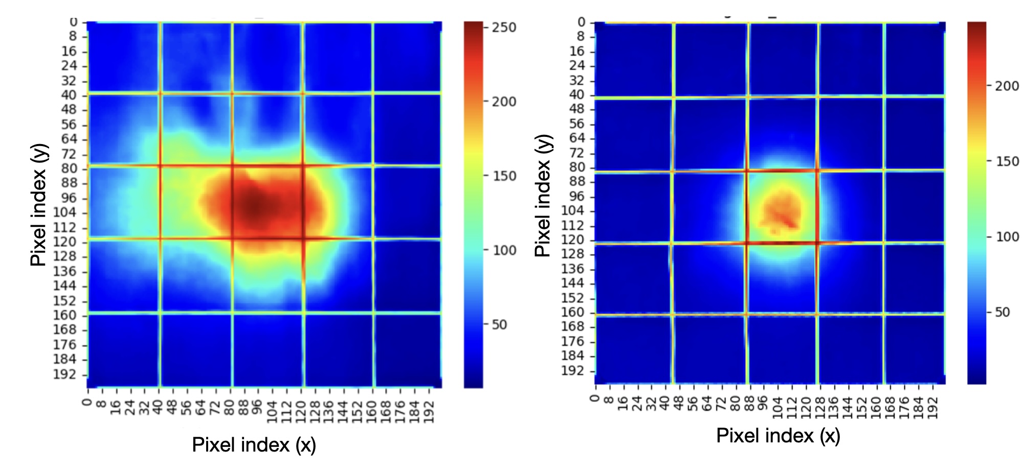
By using spherical mirrors, not only was the light intensity improved, but the beam size was also reduced, resulting in a more compact and symmetric profile, as shown in Figure 23. The relatively degraded profile observed with the convex lens optics may be attributed to the challenges in aligning the two lenses. The impact of misalignment becomes more pronounced when transmitting over long distances. This result highlights the effectiveness of spherical mirrors in maintaining beam quality over extended distances. Additionally, when conducting experiments in the ring tunnel, reflection mirrors are necessary. Spherical mirrors, which provide both focusing and reflection capabilities, reduce the number of components required compared to the use of convex lenses.
Following the successful demonstration in the above two experimental setups, further tests were conducted within the SuperKEKB tunnel. The tests involved a 244 m laser transmission from D06V1 to the boundary of D6/D7 using spherical mirrors to maintain beam quality. These tests aimed to confirm the system’s performance in a realistic operational environment. The laser was transmitted across multiple optical setups mounted on cable racks within the tunnel, achieving stable transmission and efficient light collection. The tunnel experiments demonstrated that the laser beam profile remained circular, similar to the previous experiments in the LINAC area.
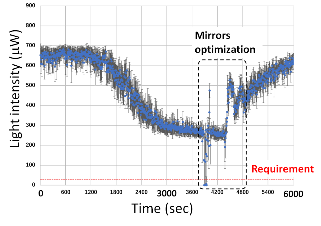
Figure 24 shows the time-dependent laser intensity measured within the SuperKEKB tunnel. While fluctuations in intensity were observed over extended periods, the system consistently met the requirement of 30 W, which is the threshold for ensuring proper operation of the abort master module. The observed degradation in intensity may be attributed to the drift in the laser’s optical path. This drift is likely caused by temperature variations within the tunnel, leading to the deformation of the frame that holds the laser optics in place. Such deformation could alter the mirror angles and subsequently the laser’s trajectory. Supporting this hypothesis, the laser intensity was restored by adjusting the mirrors’ angles. These findings demonstrate the potential viability of utilizing a laser-based abort signal system in the SuperKEKB tunnel, particularly if a remote mirror angle control system is implemented.
This innovative approach is expected to significantly enhance the speed of the abort response system, thus mitigating the damage caused by SBL and contributing to the overall efficiency and safety of the SuperKEKB accelerator.
7 Future Directions
To further advance the understanding and mitigation of SBL at SuperKEKB, we are focusing on two critical areas of beam diagnostics: Bunch Oscillation Recorder (BOR) and X-ray Beam Size Monitor (XRM). These instruments will provide valuable data on beam oscillations and beam size variations, respectively, allowing for a more comprehensive analysis of SBL events.
7.1 Bunch Oscillation Recorder (BOR)
In our new beam diagnostic system, beam losses detected by the loss monitors installed around the collimators have been the primary focus to investigate the causes of SBL events. However, upon examining beam oscillations recorded by BOR, it has been found that in many cases, oscillations begin several beam-cycles before the actual losses occur.
The BOR is designed to record the beam position bunch-by-bunch for multiple turns before a beam abort. Before LS1, a single BOR [9] was installed on each ring, primarily for the Bunch Feedback System monitor, but this setup was insufficient to pinpoint the initial cause and location of SBL events.
Moving forward, it will be crucial to acquire such oscillation data at various points around the ring. By further analyzing the oscillation data and identifying the locations where these oscillations start, we can potentially gain more insights into the causes of SBL.
As the first step towards this goal, we have developed a portable BOR [34] using Radio Frequency System on Chip (RFSoC) evaluation board ZCU111 from AMD/Xilinx in addition to the existing BOR. The RFSoC-based BOR will allow for multiple installations around the ring to cover phase advances and detect bunch oscillations more accurately. Figure 25 shows an SBL event recorded with the new RFSoC BOR.
7.2 X-ray Beam Size Monitor (XRM)
The X-ray Beam Size Monitor (XRM) [35] at SuperKEKB is designed to measure the vertical beam size using synchrotron radiation from bending magnets. The XRMs are installed one to each main ring. The current setup employs optical elements such as pinholes and coded apertures, along with a scintillator screen and a CMOS camera, for high-resolution multi-bunch measurements.
In addition, a high-speed Si-based XRM is under development to enable single-shot (single bunch, single turn) measurements, providing bunch-by-bunch vertical beam size data. This advanced system will use a deep Si detector and high-speed readout electronics with coded aperture imaging to enhance photon throughput. The new XRM will significantly improve the identification of SBL causes by allowing detailed bunch-by-bunch measurements at multiple ring locations. This capability is expected to play a crucial role in analyzing beam instabilities and enhancing low-emittance tuning for better overall accelerator performance.
8 Conclusion
Significant strides have been made in developing and implementing advanced beam diagnostic and abort systems to address the challenges posed by SBL events at SuperKEKB. The high-speed beam diagnostic system, which includes high-speed loss monitors and the WR time synchronization system, has greatly enhanced our ability to pinpoint the start of beam losses with improved temporal accuracy. The installation of additional CLAWS detectors and the expansion of abort modules have demonstrated potential for reducing beam losses by optimizing the response time of the abort system.
The possible mechanisms behind SBL events have been explored, such as beam-dust interactions and the fireball hypothesis, and acoustic sensors have been developed. Although acoustic sensors have not yet detected discharge phenomena near collimators, they remain a promising tool for future studies. Our efforts in understanding these mechanisms are ongoing, and further research is necessary to fully elucidate the causes of SBL. The development of the BOR and the XRM is expected to provide critical data, enhancing our ability to diagnose and mitigate SBL events more effectively.
The advancements made in beam diagnostics and abort systems not only aim to minimize the risks associated with SBL events but also support the overarching goal of achieving higher luminosities at SuperKEKB. These improvements will enable the Belle II experiment to collect high-statistics data essential for exploring new physics beyond the Standard Model. The success of these initiatives reflects the collaborative efforts of the SuperKEKB and Belle II teams, and we look forward to continued progress in enhancing the performance and stability of the accelerator.
Acknowledgements
We express our gratitude to the SuperKEKB accelerator team and all collaborators of the SuperKEKB and Belle II groups for their tremendous cooperation in achieving stable machine operation and aiding in the development of the beam diagnostic system and advanced beam abort system. This progress has been made possible through the participation of many graduate students from Japan and abroad in the Belle II group, as well as the understanding and support of the supervising professors regarding Machine Detector Interface (MDI) projects.
We also extend our sincere thanks to XXXX and YYYY for their valuable review and discussion regarding this paper.
This work was supported by the Ministry of Education, Culture, Sports, Science, and Technology (MEXT) of Japan, KAKENHI (Grant Numbers 22H03867, 22K21347, and 23H05433), and the US-Japan Ozaki Exchange Program [36].
References
- [1] T. Abe, et al., Belle II Technical Design Report, Tech. Rep. KEK REPORT 2010-1, KEK, arXiv:1011.0352 (2010).
- [2] E. Kou, et al., The Belle II Physics Book, Prog. Theor. Exp. Phys. 2019 (12) (2019) 123C01. doi:10.1093/ptep/ptz106.
- [3] Y. Ohnishi, et al., Accelerator design at SuperKEKB, Prog. Theor. Exp. Phys. 2013 (3) (2013) 03A011. doi:10.1093/ptep/pts083.
-
[4]
N. Toge, KEKB-factory Design
Report, Tech. Rep. KEK-Report-95-7, KEK (1995).
URL https://cds.cern.ch/record/475260 - [5] S. Kurokawa, E. Kikutani, Overview of the KEKB accelerators, Nucl. Instrum. Methods Phys. Res., Sect. A 499 (1) (2003) 1–7. doi:10.1016/S0168-9002(02)01771-0.
- [6] Y. Suetsugu, K. Shibata, T. Ishibashi, M. Shirai, S. Terui, K. Kanazawa, H. Hisamatsu, M. L. Yao, SuperKEKB vacuum system operation in the last 6 years operation, Phys. Rev. Accel. Beams 26 (2023) 013201. doi:10.1103/PhysRevAccelBeams.26.013201.
- [7] N. Ohuchi, et al., SuperKEKB beam final focus superconducting magnet system, Nucl. Instrum. Methods Phys. Res., Sect. A 1021 (2022) 165930. doi:https://doi.org/10.1016/j.nima.2021.165930.
- [8] I. Adachi, T. Browder, P. Krizˇan, S. Tanaka, Y. Ushiroda, Detectors for extreme luminosity: Belle II, Nucl. Instrum. Methods Phys. Res., Sect. A 907 (2018) 46–59. doi:10.1016/j.nima.2018.03.068.
- [9] M. Tobiyama, J. W. Flanagan, Development of Bunch Current and Oscillation Recorder for SuperKEKB Accelerator, in: Proceedings of IBIC2012, Tsukuba, Japan, JACoW Publishing, 2012, mOPA36.
- [10] H. Nakayama, Y. Suetsugu, K. Kanazawa, Y. Ohnishi, Y. Funakoshi, K. Ohmi, D. Zou, Small-beta collimation at SuperKEKB to stop beam-gas scattered particles and to avoid transverse mode coupling instability, in: Proc. 3rd International Particle Accelerator Conference (IPAC2012), 2012, p. 1104.
- [11] A. Piwinski, The Touschek Effect in Strong Focusing Storage Rings (1999). doi:10.48550/ARXIV.PHYSICS/9903034.
- [12] A. Natochii, et al., Measured and projected beam backgrounds in the Belle II experiment at the SuperKEKB collider, Nuclear Instruments and Methods in Physics Research Section A: Accelerators, Spectrometers, Detectors and Associated Equipment 1055 (2023) 168550. doi:10.1016/j.nima.2023.168550.
- [13] T. Ishibashi, S. Terui, Y. Suetsugu, K. Watanabe, M. Shirai, Movable collimator system for SuperKEKB, Phys. Rev. Accel. Beams 23 (12) (2020) 053501. doi:10.1103/PhysRevAccelBeams.23.053501.
-
[14]
A. Faus-Golfe, F. Zimmermann, J. Resta-López,
Non-Linear Collimation in Linear
and Circular Colliders, in: Proceedings of EPAC 2006, CERN, 2006.
URL https://cds.cern.ch/record/928281 -
[15]
Shinji Terui, Yoshihiro Funakoshi, Takuya Ishibashi, Haruyo Koiso, Yu
Morikawa, Akio Morita, Hiroyuki Nakayama, Andrii Natochii, Yukiyoshi
Ohnishi, Kazuhito Ohmi, Kyo Shibata, Mitsuru Shirai, Yusuke
Suetsugu, Makoto Tobiyama, Ryuichi Ueki, Demin Zhou,
Challenges Related to SuperKEKB
Collimators, in: Proceedings of the 20th Annual Meeting of Particle
Accelerator Society of Japan, Particle Accelerator Society of Japan, 2023.
URL https://cds.cern.ch/record/1304162 - [16] S. Terui, Y. Funakoshi, T. Ishibashi, H. Koiso, M. Masuzawa, Y. Morikawa, A. Morita, S. Nakamura, H. Nakayama, Y. Ohnishi, K. Ohmi, K. Shibata, M. Shirai, Y. Suetsugu, M. Tobiyama, R. Ueki, D. Zhou, K. Oide, A. Natochii, Collimator challenges at SuperKEKB and their countermeasures using nonlinear collimator, Phys. Rev. Accel. Beams 27 (2024) 081001. doi:10.1103/PhysRevAccelBeams.27.081001.
- [17] T. Mimashi, et al., SuperKEKB Beam abort System, in: Proc. 5th International Particle Accelerator Conference (IPAC’14), Dresden, Germany, June 15-20, 2014, no. 5 in International Particle Accelerator Conference, JACoW, 2014, pp. 116–118. doi:https://doi.org/10.18429/JACoW-IPAC2014-MOPRO023.
- [18] H. Ikeda, M. Arinaga, J. W. Flanagan, H. Fukuma, M. Tobiyama, Beam loss monitor at SuperKEKB, in: Proc. International Beam Instrumentation Conference (IBIC’14), 2014, pp. 459–462.
-
[19]
S. Bacherh, G. Bassia, L. Bosisio, G. Cautero, P. Cristaudo, M. Dorigo,
A. Gabrielli, D. Giuressi, K. Hara, Y. Jin, C. L. Licata, L. Lanceri,
R. Manfredi, H. Nakayama, K. R. Nakamura, A. Natochii, A. Paladino, G. Rizzo,
L. Vitale, H. Yin,
Performance of the
diamond-based beam-loss monitor system of Belle II, Nuclear Instruments and
Methods A 997 (2021) 165157.
URL https://doi.org/10.1016/j.nima.2021.165157 - [20] M. Gabriel, F. Simon, H. Windel, Y. Funakoshi, M. Hedges, N. Iida, I. Jaegle, C. Kiesling, N. van der Kolk, P. Lewis, H. Nakayama, Y. Ohnishi, R. de Sangro, Y. Suetsugu, M. Szalay, S. Vahsen, A time resolved study of injection backgrounds during the first commissioning phase of SuperKEKB, The European Physical Journal C 81 (972) (2021). doi:10.1140/epjc/s10052-021-09769-3.
-
[21]
H. Windel, An injection background
monitoring system for the second and third phase of the SuperKEKB
commissioning, Ph.D. thesis, Technical University of Munich (2021).
URL https://mediatum.ub.tum.de/1624845 - [22] F. Simon, Silicon photomultipliers in particle and nuclear physics, Nuclear Instruments and Methods in Physics Research Section A: Accelerators, Spectrometers, Detectors and Associated Equipment 926 (2019) 85–100. doi:10.1016/j.nima.2018.11.042.
- [23] Y. Liu, V. Büscher, J. Caudron, P. Chau, S. Krause, L. Masetti, U. Schäfer, R. Spreckels, S. Tapprogge, R. Wanke, A design of scintillator tiles read out by surface-mounted SiPMs for a future hadron calorimeter, in: 2014 IEEE Nuclear Science Symposium and Medical Imaging Conference (NSS/MIC), 2014, pp. 1–4. doi:10.1109/NSSMIC.2014.7431118.
- [24] Y. Ashida, et al., Development of an Electron Multiplier Tube for the T2K experiment, Prog. Theor. Exp. Phys. 2018 (2018) 103H01.
- [25] White Rabbit Project, White Rabbit, http://white-rabbit.web.cern.ch/.
- [26] M. Sullivan, et al., Beam damage to PEP-II collimators, in: Proceedings of EPAC 2006, MOPLS049, 2006.
- [27] B. Lindstrom, et al., Unidentified Falling Objects in the Large Hadron Collider, Phys. Rev. Accel. Beams 23 (2020) 124501.
- [28] Y. Suetsugu, H. Fukuma, K. Shibata, M. Pivi, L. Wang, Beam tests of a clearing electrode for electron cloud mitigation at KEKB Positron Ring, in: Proceedings of the International Particle Accelerator Conference, ICR, 2010, pp. 2369–2371.
- [29] H. Ikeda, et al., Observation and cause investigation of sudden beam loss at SuperKEKB, in: Proceedings of the 21st Annual Meeting of Particle Accelerator Society of Japan (PASJ2024), 2024.
- [30] KEK Accelerator Laboratory, The fireball hypothesis, https://www2.kek.jp/accl/topics/topics181227.html, accessed: 2024-06-30.
- [31] J. Frisch, W. Baumgartner, K. Jobe, D. McCormick, M. Ross, Acoustic measurement of RF breakdown in high gradient RF structures, eConf C000821 (2000) TUE03.
- [32] S. Sasaki, et al., Development of an abort trigger system for superkekb, in: Proceedings of ICALEPCS2015, MOPGF141, 2015.
-
[33]
K. Kitamura, Master’s Thesis: Development of Laser-Based Beam
Abort System at SuperKEKB (2023).
URL {}{}}{https://www-hep.phys.se.tmu.ac.jp/thesis/doc/2023-Mthesis-kitamura.pdf}{cmtt} - [34] R.~Nomaru, L.~Ruckman, G.~Mitsuka, Analyzing Sudden Beam Loss in the SuperKEKB/Belle-II Experiment with RFSoC Technology, in: 15th International Particle Accelerator Conference, Nashville, TN, JACoW Publishing, 2024. doi:10.18429/JACoW-IPAC2024-TUBD3.
- [35] E.~Mulyani, J.~W. Flanagan, M.~Tobiyama, H.~Fukuma, H.~Ikeda, G.~Mitsuka, First measurements of the vertical beam size with an X-ray beam size monitor in SuperKEKB rings, Nuclear Instruments and Methods in Physics Research Section A: Accelerators, Spectrometers, Detectors and Associated Equipment 919 (2019) 1--15. doi:https://doi.org/10.1016/j.nima.2018.11.116.
- [36] US-Japan Science and Technology Cooperation Program in High Energy Physics (the Ozaki Exchange Program), https://www.bnl.gov/ozaki/.