Practical Challenges for Reliable RIS Deployment in Heterogeneous Multi-Operator Multi-Band Networks ††thanks: This research is supported by Business Finland via project 6GBridge - Local 6G (Grant Number: 8002/31/2022), and Research Council of Finland, 6G Flagship Programme (Grant Number: 346208).
Abstract
Reconfigurable intelligent surfaces (RISs) have been introduced as arrays of nearly passive elements with software-tunable electromagnetic properties to dynamically manipulate the reflection/transmission of radio signals. Research works in this area are focused on two applications, namely user-assist RIS aiming at tuning the RIS to enhance the quality-of-service (QoS) of target users, and the malicious RIS aiming for an attacker to degrade the QoS at victim receivers through generating intended destructive interference. While both user-assist and malicious RIS applications have been explored extensively, the impact of RIS deployments on imposing unintended interference on various wireless user-equipments (EUs) remains underexplored. This paper investigates the challenges of integrating RISs into multi-carrier, multi-user, and multi-operator networks. We discuss how RIS deployments intended to benefit specific users can negatively impact other users served at various carrier frequencies through different network operators. While not an ideal solution, we discuss how ultra-narrowband metasurfaces can be incorporated into the manufacturing of RISs to mitigate some challenges of RIS deployment in wireless networks. We also present a simulation scenario to illuminate some practical challenges associated with the deployment of RISs in shared public environments.
Index Terms:
RIS, RIS-induced interference, multi-carrier, multi-operator, wireless networksI Introduction
Reconfigurable intelligent surfaces (RISs) are emerging as a technology for enhancing the quality of wireless communication by dynamically manipulating the reflection/transmission of radio signals. Engineered with a large number of nearly passive elements with software-tunable electromagnetic properties, these programmable surfaces manipulate radio waves, offering the potential to impact the signal-to-interference-plus-noise ratio (SINR) for target users. Research in this area has primarily focused on two key applications of RISs. The first application, referred to as user-assist RIS, aims to improve the quality of communication [1] or energy transfer [2] between a transmitter and intended receiver/receivers particularly when a direct line-of-sight (LoS) path is unavailable and the direct channel gain experiences a high path loss due to obstructions. This is accomplished by intelligently directing incident signals at the RIS towards intended users [3, 4]. Conversely, the second application, known as malicious RIS, involves the deliberate manipulation of radio waves to disrupt targeted users’ communication links during data transmission or channel estimation. In such adversarial scenarios, an attacker controls the RIS to degrade the SINR at victim receivers and weaken their quality of service (QoS) [5].
While both beneficial and disruptive applications of user-assist and malicious RISs have been explored extensively, the impact of RIS deployments on imposing unintended interference on various wireless user-equipments (EUs) remains underexplored. This is particularly crucial in real-world scenarios where a variety of wireless services operating at different carrier frequencies and potentially served by different and independent operators111Throughout this paper, the term operator is used to encompass both licensed network operators (e.g., mobile network operators) and entities responsible for the operation of unlicensed networks (e.g., WiFi network administrators). might coexist in close proximity to deployed RISs. Existing research often focuses on deploying RISs for a single service provider at a specific carrier frequency, neglecting the potential of side effects imposed on other users operating on different frequencies. Recently, some works have studied the implementation of RISs in multi-operator/provider networks to manage the resource allocation of RIS-assisted UEs [6, 7]. The general idea is to optimize the scattering matrix of the RIS through a multi-objective optimization problem where an aggregate/joint performance measure relating to UEs from several operators is optimized, and/or some frequency-dependant QoS constraints are considered to be held for non-target UEs. However, the practical application of these works encounters significant limitations. Firstly, these studies consider a small number of UEs operating within specified service types. Consequently, there is no provision to accommodate a diverse range of service types for various UEs each operating at a dedicated frequency band. Additionally, these methods require that the channel estimation of the corresponding UEs serviced by different operators is achieved in a synchronized scheme and all Channel State Information (CSI) between the transmitters/Base Stations (BSs), RISs, and UEs are universally accessible for the network, where the control of RIS scattering matrix, along with beamforming and resource allocation for all UEs served by different operators, is executed in a centralized manner involving all network operators. Finally, including all non-target UEs in the optimization process for a target UE degrades the QoS of those UEs previously optimized independently. These assumptions and limitations impose practical challenges in public wireless environments. For instance, in the vicinity of the deployed RISs, there may be UEs utilizing a variety of standardized technologies that exploit licensed or unlicensed spectrum, such as Bluetooth, WiFi, xG cellular services, and others. Incorporating RIS considerations into these technologies is not feasible, as these technologies execute resource allocation at their dedicated frequency bands independently of others based on their own QoS requirements and standardized protocols and restrictions.
Integrating RISs into complex heterogeneous wireless networks with diverse services, operators, and frequencies can negatively impact the QoS and reliability of existing connections. This means that benefiting one user serviced by some operator through RIS activation could potentially lead to service deterioration for other users who previously enjoyed reliable connectivity via their own servicing operators. Consequently, reliable communication links, previously exceeding QoS requirements, might become unreliable after RIS deployment due to unintended wireless channel alterations on other frequencies. This behavior presents a significant challenge for deploying RISs effectively and reliably in public environments. Further research is needed to develop practical and low-overhead RIS resource allocation in multi-band, multi-operator networks. Additionally, regulatory considerations for the reliable deployment of RISs in such networks must be inspected.
The remainder of this paper is structured as follows: In Section II we investigate into the QoS and reliability challenges associated with RISs in a single-carrier, multi-user network. In sections III and IV we study the dark sides of employing RIS in multi-user, multi-carrier, multi-operator networks. Finally, we present a simulation scenario that demonstrates the dual nature of RISs; while they enhance the QoS for the intended UEs, they can simultaneously decrease the network and connection reliability for other UEs operating in the vicinity of the RISs.
II RIS-Induced QoS Challenges in Single-Carrier Multi-User Networks
Single-carrier multi-user communication is the common scenario studied in most works in the literature for RIS-aided user-assist multiple-input-multiple-output (MIMO) communications. Consider a downlink communication scenario where a BS transmits data streams to UEs. Existing research typically optimizes an objective function (e.g., sum rate of UEs) by adjusting both the precoder at the BS and the scattering matrix (corresponding to the phase shifts) of the RIS. Guaranteeing a minimum QoS level for each UE becomes crucial when reliable links are essential. This translates into a set of feasibility constraints for UEs that must be incorporated into the main optimization problem.
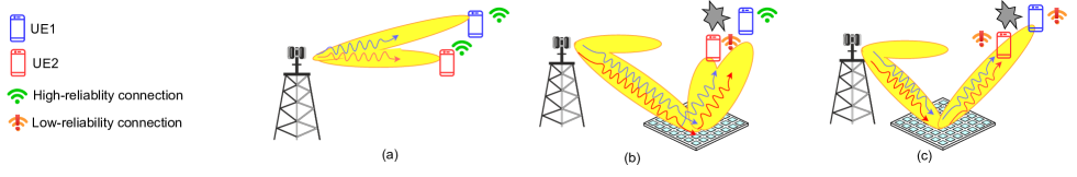
Fig. 1-a depicts a scenario showing a BS serving two UEs where LoS paths exist for both and the channels are not highly correlated. In this case, achieving an acceptable QoS level is possible by adjusting a suitable MIMO precoder without requiring RIS deployment. Now consider the scenario in Fig. 1-b, where the LoS path to UE1 is blocked. Here, an RIS is deployed to restore the reliability of the connection of UE1. However, optimizing the RIS scattering matrix and the BS precoder to guarantee UE1’s reliability might come at the expense of UE2’s loss of reliability. This might occur due to several reasons: (a) Reduced Direct Power: To prioritize UE1’s QoS, the BS transmits less power directly towards UE2, (b) Incoherence: The direct radiated power toward UE2 and the reflected power from the RIS might experience some degree of incoherence, further degrading the signal quality for UE2, and finally (c) Interference: The reflected power intended for UE1 can also reach UE2; Mitigating this interference can be sometimes difficult due to the geometrical positions of the UEs relative to the RIS. For example, Fig. 1-c illustrates a case where both UEs might be negatively affected if RIS is incorporated. The uncorrelated Bs-to-UEs’ channel matrices employed for efficient MIMO communication in Fig. 1-a are undermined by the highly correlated RIS-to-UEs’ channels matrices in this scenario due to UE2 being located in the LoS dominant path between the RIS and UE1. This situation makes it challenging to design efficient MIMO precoders to eliminate interference between the UEs, potentially leading to QoS reliability issues for both UE1 and UE2. These factors highlight the trade-offs inherent in RIS deployment for single-carrier multi-user networks. While it may improve the communication quality for a target user, it can also negatively impact the QoS of other users. To mitigate this, further techniques might be required to be incorporated, including RIS-aware rescheduling and carrier assignment. For example, a solution to resolve the precoder design issues in scenarios like Fig. 1-b and Fig. 1-c is to assign independent precoders by considering different carriers allocated to UE1 and UE2. However, the multi-carrier scenario introduces other challenges, which are investigated in the following section.
III RIS Deployment in Heterogeneous Multi-Carrier Multi-Operator Networks: Reasons Behind Reliability Risks
The reliable deployment of RISs becomes more challenging in practice where a variety of UEs operate in different frequency bands and are served by various operators. Hereafter, we use the term target UE/UEs to refer to the one/ones for which the RIS’s scattering matrix is to be tuned. All other UEs existing in the vicinity of the RIS are referred to as non-target UEs. The corresponding carrier frequencies are respectively referred to as target and non-target carrier frequencies. The reliability hazards of an RIS in real-world multi-carrier heterogeneous networks stem from two important properties investigated in the following subsections.
III-A Frequency Response of RISs
From a system-level perspective, RISs operate similarly to active relays forwarding the transmission beam toward target UEs. However, relays utilize various active and passive filtering levels to ensure that only the signal with the intended carrier frequency is processed and forwarded. Here, the effective frequency response is the cascaded effect of several filters including wideband frequency responses of the relay’s receive and transmit antennas, mid-bandwidth bandpass analog filters such as the ones for eliminating out-of-band noise, and finally, sharp low-bandwidth digital filters for fine-tuning and passing only the intended low-bandwidth signal at the target carrier frequency. In contrast, the frequency domain filtering of RISs is limited to the inherent wideband frequency response of the reflecting surfaces, which allows a broad range of carrier frequencies associated with other UEs and networks to pass through. The range of frequencies that an RIS can impact signal propagation in either reflective or transmissive mode is defined as the bandwidth of influence (BoI) [8]. Table I compares the fractional BoI (the ratio of BoI over the central frequency) for 4 different types of typical RIS unit cells validated through experimental results in the European Union Horizon 2020 RISE-6G project [8]. To compare the fractional BoI data in Table I with the corresponding value required for a typical cellular UE connection, consider a 5G network operating at the FR1 1.8 GHz frequency, and assume that a resource block of 12 consecutive subcarriers each having a 30 kHz subcarrier spacing is completely allocated to some UE. Here, the total allocated bandwidth is KHz and the corresponding fractional BoI is %. Comparing this with the values expressed in Table I reveals how significantly the fractional BoI of RISs exceeds what is required by a typical 5G target UE. While narrowing the bandwidth of reflective/transmissive RISs can be somewhat achievable through specialized RIS’s elements design, this approach can compromise the surface’s reflectivity/transmissivity and, in any case, cannot replicate the sharp digital filtering and mid-bandwidth analog filters employed in active relays.
| RIS Type | BoI (GHz) | BoI/ |
|---|---|---|
| 1-bit transmissive | [23.9 30.6] | 24.5% |
| varactor-based reflective | [5.1 6.4] | 22.4% |
| RF-switch-based transmissive | [5.17 5.44] | 5.1% |
| PIN-diode-based transmissive | [23.9 30.6] | 23.7% |
In recent years, the fabrication of ultra-narrowband (UN) metasurface antennas has been investigated, where the antenna bandwidth can be reduced to less than 1 percent of the carrier frequency through employing special kinds of metamaterials (e.g., [9]). While such metasurfaces have been explored and fabricated as transmit and receive antennas, they can potentially be incorporated into RISs as well. However, this integration poses several challenges. Firstly, the manufacturing complexity and cost of UN metasurfaces are much higher than those of ordinary metasurfaces, especially when designed in the form of arrays with many meta-atoms. This complexity contradicts one of the main goals of RISs, which is to be cost-effective and easily mountable. Secondly, in practical wireless communications, single/multiple carrier frequencies from a pool of carriers in the available spectrum are dynamically allocated to target UEs. Consequently, there might exist no preallocated carrier frequency for RISs. As a result, the bandwidth of the designed RIS must encompass all carriers in the available spectrum, which, on the other hand, leads to the harmful reflection of all signals with carrier frequencies allocated to non-target UEs served in the available spectrum.
III-B Beam Squint; A Destructive Issue Associated with RIS-Aided Narrowband/Wideband Communications
Beam squint is a known phenomenon in beamforming using phased-array antennas. This generally refers to the deviation of the main beam direction when the radiated signal frequency spans over a large spectrum as is the case in wideband signal applications. The investigation of beam squint in non-RIS-aided and RIS-aided beamforming applications has been addressed in many works (e.g., [10, 11]), however, these works consider the beam squint for the case where a wideband signal relating to a target signal is radiated from an intended transmitter. In practice, however, even in narrowband RIS-aided communications, beam squint is unavoidable. This means that the RIS scatters unwanted signals with different frequencies in various directions, potentially resulting in interfering effects for different UEs operating around the RIS. The frequency-dependent radiation of metasurfaces has been explored in some works (e.g., [12]). To elaborate more on this from a system-level perspective, consider an -element reflective RIS. The reflective behavior of the RIS can be characterized by the circuit model depicted in Fig. 2 [13, 7]. The reflection pattern of the RIS is determined by tuning the scattering matrix . There exists a one-to-one relationship between the scattering matrix and the impedance matrix , where is the impedance connected to port and is the one connected between ports and . The conventional diagonal corresponds to isolated ports (), while recently introduced beyond-diagonal RISs allow for coupled ports.
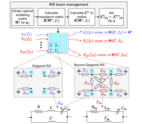
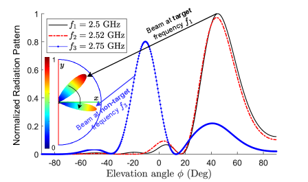
In either case, as depicted in the RIS beam management block in Fig. 2, practical RIS beam management for target UEs operating at target carrier frequency involves these steps: (a) Calculate the optimal scattering matrix to reflect the optimal beam towards target UEs, (b) Obtain the corresponding impedance matrix using a procedure outlined in [13] and [7] for diagonal and beyond-diagonal RIS models, respectively, (c) Finally, calculate and tune the capacitance matrix corresponding to the realization of . It is seen that at each carrier frequency corresponding to some non-target UE, the scattering matrix depends on a fixed term corresponding to the capacitance matrix , as well as a variable term corresponding to the carrier frequency . Noting that a wide range of non-target signals with carrier frequencies , might exist in the vicinity of the RIS, the incident signals are reflected in different directions, each based on its scattering matrix and the angle of arrival (AoA). These reflections can potentially have detrimental effects, as discussed in the next section. To visualize this, consider a diagonal RIS in a scenario described in Fig. 3. The scattering matrix is configured for the target carrier frequency GHz. The impedance matrix parameters are set according to [13]. Assume signals for two other non-target UEs also impinge on the RIS surface at the same AoA, but with carrier frequencies GHz and GHz. Notably, a small frequency deviation from to results in a reflection pattern for non-target signal that closely resembles that of the target signal . In contrast, changing the frequency from GHz to GHz leads to a significant deviation in the reflection direction from to , corresponding to the target and non-target reflected beams respectively. Note that unlike the conventional study of beam squint for wideband target signals, here the existence of beam squint for any traveling signal at carrier frequency is not contingent on whether the target signal is narrowband or wideband. However, the beam squint is not the case if the RIS comprises ultra-narrowband metasurface elements.
IV RIS Deployment in Heterogeneous Multi-Carrier Multi-Operator Networks: Scenarios Resulting in Reliability Risks
Building upon the inherent issues of passive RIS technology discussed in the previous section, in what follows we examine the main reasons and specific scenarios where these issues can lead to unintended QoS consequences for non-target UEs.
IV-A Destructive Self-Interference
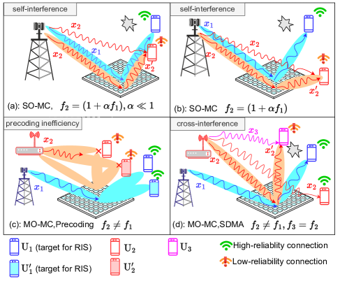
Recall that RISs reflect the signals transmitted for non-target UEs as well. These reflections can impose destructive interference on corresponding UEs. To showcase some examples, Fig. 4-a and 4-b illustrate scenarios in a network where the RIS scattering matrix is to be tuned for the target user operating at frequency , which in turn affects a non-target user operating at frequency . Depending on the channel model assumption, various harmful self-interference effects for the non-target UE can be considered. Generally, the reflected rays from each array element to the non-target UE are added to the signal received from the direct path forming a multi-path fading channel. If the LoS channel model is considered, the beam pattern shaped by the RIS and potentially directed toward the non-target UE might increase the interference. If the non-target frequency is close to , the reflected signal experiences negligible beam squint (Fig. 4-a). Otherwise, the main lobe of the reflected signal points in a different direction from that of the target reflected signal (Fig. 4-b). In either case, when the non-target UE lies within the main lobe of the reflected signal as shown in Fig. 4-a-b, QoS degradation is likely due to the potential incoherent multi-path arrival of the signal rays. While the RIS can be tuned to ensure the constructive arrival of signals from the direct path and reflected path, building optimal QoS for target UEs, this does not hold for non-target UEs at the same time.
IV-B CSI Perturbation and Inaccuracy of Precoding
The scattering matrix of an RIS is continuously and frequently updated based on the CSI update scheduling considering changes of BS-to-RIS and RIS-to-target-UE channels without considering the impact on non-target UEs. Noting that the CSI estimation scheduling of the non-target UEs operating under different network protocols and managed by separate network coordinators are not synchronized with that of the target UEs, the estimated channels of non-target UEs become outdated as soon as the RIS scattering matrix is reconfigured for target UEs. This desynchronization leads to a reduction in the channel coherence time, making it unpredictable and thereby degrading the signal quality and connection reliability experienced by non-target UEs. For multi-operator MIMO communications, where each BS is supposed to serve multiple MIMO links at each dedicated carrier frequency, as depicted in Fig. 4-c, this together with the destructive self-interference for non-target UEs results in increasing decoding error probability due to inaccurate and out-dated computed precoders.
IV-C Destructive Cross-Interference
This occurs when the RIS disrupts the spatial domain orthogonality of channel access for the UEs operating at the same carrier frequency. Consider a communication scenario shown in Fig. 4-d where is the target user of the RIS and the non-target UEs ( and ) are spatially separated and served by another operator on the same carrier frequency using spatial division multiple access (SDMA). Although and are considered to be sufficiently separated in the angular domain with respect to the corresponding transmitter to ensure effective SDMA performance, the deployment of the RIS may cause the signal intended for to be reflected toward . As a result, cochannel cross-interference for becomes a more challenging scenario compared to the previously discussed self-interference scenario. Unlike self-interference, which may occasionally be non-destructive, the cross-interference caused by RIS reflection is consistently destructive.
V Numerical Results
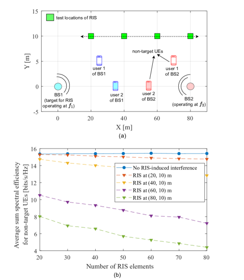
In this section, we provide a simulation setup to evaluate the detrimental consequence of RIS deployment in multi-operator networks and show how deploying RISs to benefit the UEs served by some operators can harm other UEs located in the vicinity of the RIS served by other operators on carrier frequencies within the BoI of the RIS. We have considered a MIMO network with two operators each having one BS with antennas. We consider that BS1 and BS2 are served by operator 1 and operator 2 at frequencies GHz and GHz respectively. A two-dimensional network scenario is investigated according to Fig. 5 where an -element diagonal RIS is considered to be located on 4 test positions, and the RIS phase shifters are adjusted by tuning the scattering matrix to maximize the weighted sum power of target-UEs [14, 7]. The impedance matrix is obtained from the ideal diagonal model presented in Fig. 2. The channel model and RIS model parameter values, as well as the solution scheme for finding the scattering matrix are adopted from [14, 7]. Here, we assume that the precoders of non-target UEs are tuned independently without the involvement of RIS, as the RIS is owned and controlled by the first operator to benefit its users. The tunning of the scattering matrix for target UEs operating at results in a change in the channel matrix of non-target UEs operating at , in a mechanism expressed in Section III-B, which leads to the performance degradation for non-target UEs due to the increase in decoding error probability. It is seen from the figure that the RIS-induced performance degradation is relatively high, especially when the number of RIS elements gets higher and the RIS gets closer to non-target UEs. For example, considering a 70-element RIS located at (60,10)m, the average sum spectral efficiency for non-target UEs is decreased by a factor of 48% from 15.4 b/s/Hz to 8 b/s/Hz corresponding to RIS-interference-free (no RIS) and RIS-induced interference scenarios.
VI Conclusion
In this paper, we explored how RIS deployments intended to benefit specific users can negatively impact other users serviced by different network operators. This underscores the fact that the RIS design and its deployment in public environments require careful consideration. Given the potential impact on users across different networks, a robust regulatory framework is essential to mitigate these adverse effects and establish clear performance metrics, interference limits, and certification requirements for RIS deployments in multi-band multi-operator public network environments.
References
- [1] E. C. Strinati, G. C. Alexandropoulos, H. Wymeersch, B. Denis, V. Sciancalepore, R. D’Errico, A. Clemente, D.-T. Phan-Huy, E. De Carvalho, and P. Popovski, “Reconfigurable, Intelligent, and Sustainable Wireless Environments for 6G Smart Connectivity,” IEEE Communications Magazine, vol. 59, no. 10, pp. 99–105, 2021.
- [2] E. Shi, J. Zhang, S. Chen, J. Zheng, Y. Zhang, D. W. Kwan Ng, and B. Ai, “Wireless Energy Transfer in RIS-Aided Cell-Free Massive MIMO Systems: Opportunities and Challenges,” IEEE Communications Magazine, vol. 60, no. 3, pp. 26–32, 2022.
- [3] R. Liu, M. Li, H. Luo, Q. Liu, and A. L. Swindlehurst, “Integrated Sensing and Communication with Reconfigurable Intelligent Surfaces: Opportunities, Applications, and Future Directions,” IEEE Wireless Communications, vol. 30, no. 1, pp. 50–57, 2023.
- [4] P. Wang, J. Fang, W. Zhang, Z. Chen, H. Li, and W. Zhang, “Beam Training and Alignment for RIS-Assisted Millimeter-Wave Systems: State of the Art and Beyond,” IEEE Wireless Communications, vol. 29, no. 6, pp. 64–71, 2022.
- [5] Y. Wang, H. Lu, D. Zhao, Y. Deng, and A. Nallanathan, “Wireless Communication in the Presence of Illegal Reconfigurable Intelligent Surface: Signal Leakage and Interference Attack,” IEEE Wireless Communications, vol. 29, no. 3, pp. 131–138, 2022.
- [6] D. Gürgünoğlu, E. Björnson, and G. Fodor, “Combating Inter-Operator Pilot Contamination in Reconfigurable Intelligent Surfaces Assisted Multi-Operator Networks,” IEEE Transactions on Communications, pp. 1–1, 2024.
- [7] A. S. de Sena, M. Rasti, N. H. Mahmood, and M. Latva-aho, “Beyond Diagonal RIS for Multi-Band Multi-Cell MIMO Networks: A Practical Frequency-Dependent Model and Performance Analysis,” arXiv preprint arXiv:2401.06475, 2024.
- [8] G. C. Alexandropoulos, D.-T. Phan-Huy, K. D. Katsanos, M. Crozzoli, H. Wymeersch, P. Popovski, P. Ratajczak, Y. Bénédic, M.-H. Hamon, S. H. Gonzalez, et al., “RIS-enabled smart wireless environments: Deployment scenarios, network architecture, bandwidth and area of influence,” EURASIP Journal on Wireless Communications and Networking, vol. 2023, no. 1, p. 103, 2023.
- [9] Q. Shangguan, Z. Chen, H. Yang, S. Cheng, W. Yang, Z. Yi, X. Wu, S. Wang, Y. Yi, and P. Wu, “Design of ultra-narrow band graphene refractive index sensor,” Sensors, vol. 22, no. 17, p. 6483, 2022.
- [10] Z. Li, Z. Gao, and T. Li, “Sensing User’s Channel and Location With Terahertz Extra-Large Reconfigurable Intelligent Surface Under Hybrid-Field Beam Squint Effect,” IEEE Journal of Selected Topics in Signal Processing, vol. 17, no. 4, pp. 893–911, 2023.
- [11] S.-H. Park, B. Kim, D. K. Kim, L. Dai, K.-K. Wong, and C.-B. Chae, “Beam Squint in Ultra-Wideband mmWave Systems: RF Lens Array vs. Phase-Shifter-Based Array,” IEEE Wireless Communications, vol. 30, no. 4, pp. 82–89, 2023.
- [12] D. Dardari and D. Massari, “Using MetaPrisms for Performance Improvement in Wireless Communications,” IEEE Transactions on Wireless Communications, vol. 20, no. 5, pp. 3295–3307, 2021.
- [13] W. Cai, R. Liu, M. Li, Y. Liu, Q. Wu, and Q. Liu, “IRS-Assisted Multicell Multiband Systems: Practical Reflection Model and Joint Beamforming Design,” IEEE Transactions on Communications, vol. 70, no. 6, pp. 3897–3911, 2022.
- [14] A. S. de Sena, J. Kibiłda, N. H. Mahmood, A. Gomes, and M. Latva-Aho, “Malicious RIS Versus Massive MIMO: Securing Multiple Access Against RIS-Based Jamming Attacks,” IEEE Wireless Communications Letters, vol. 13, no. 4, pp. 989–993, 2024.