Anisotropic sub-band splitting mechanisms in strained HgTe: a first principles study
Abstract
Mercury telluride is an intriguing compound that is well known for the first realization of topological states. Despite being known for a long time, a quantitative understanding of its electronic properties remains challenging due to the presence of many concomitant subtle effects. By combining accurate first principles calculations and modelling, we investigate the topological phase diagram of mercury telluride as a function of strain. Our research demonstrates the significance of including the linearly -dependent higher-order strain terms into the usual treatment. In particular, we report a unique -dependence of the sub-band splitting, which arises from the interplay between strain and the standard bulk inversion asymmetry terms within our model. The impact of this phenomenon is explored in relation to the camel’s back shape during the tensile strain phase and its implications for the Weyl semimetal state in the compressive strain case are discussed.
1 Introduction
Topological properties of solid-state systems have attracted large interest in the last years. New states of matter have been observed and a new paradigm has been introduced to describe phase transitions that cannot be characterized within the classical Landau theory [1, 2, 3, 4, 5]. Mercury telluride (\ceHgTe) has played a crucial role in this regard, being the first platform where many of these ideas found experimental realization [6].
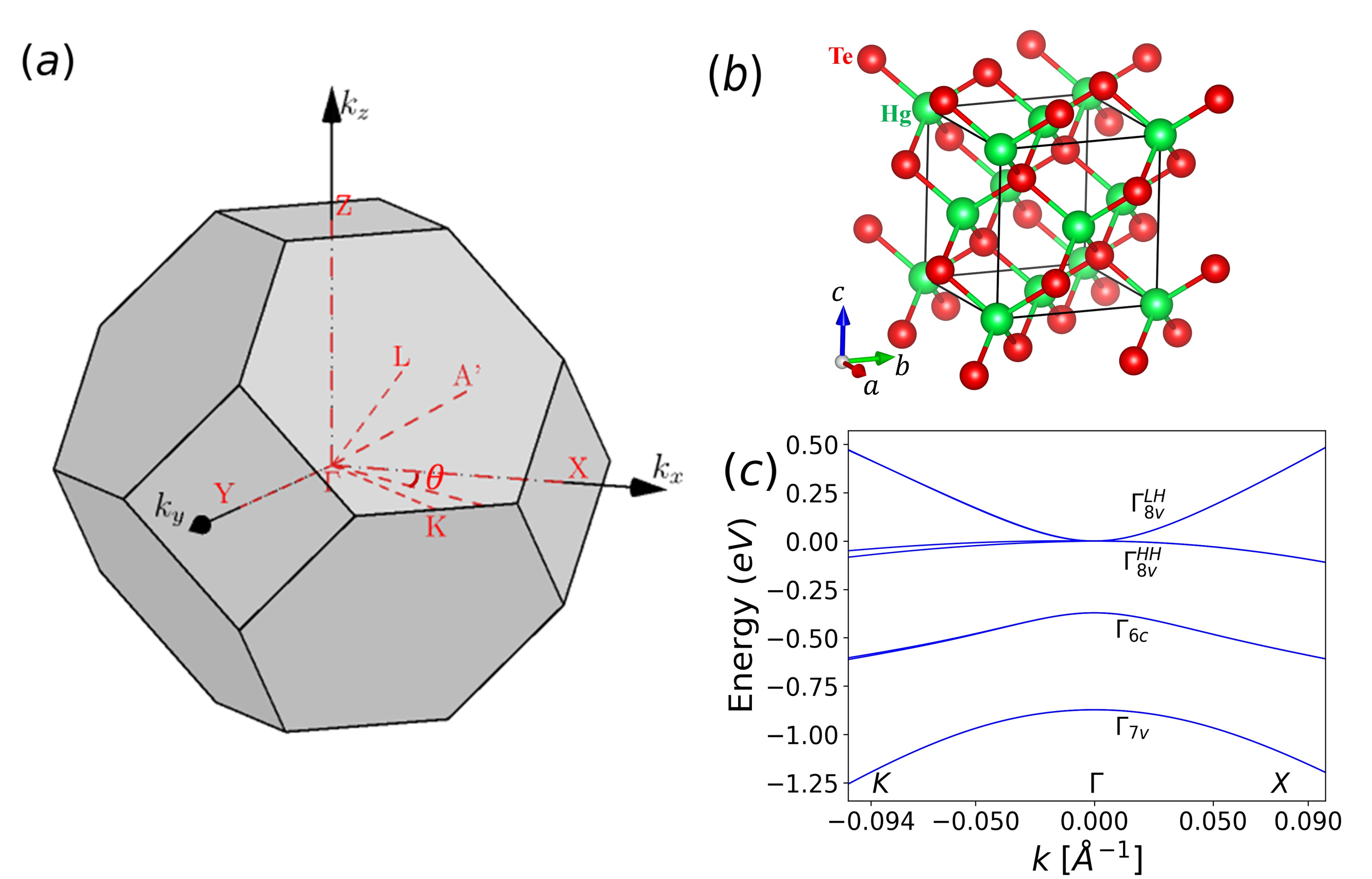
The nontrivial topological properties of \ceHgTe are related to its low-energy electronic structure around the point of the Brillouin zone. In the unstrained state, \ceHgTe is semimetallic in nature whereas a band inversion between Hg(s) and Te(p) states can be observed when a considerable tensile strain is applied on the system [7, 8]. Under compressive strain and much smaller tensile strain, \ceHgTe transforms into a Weyl semimetal [9, 10].
The advanced models typically employed to describe the electronic band structure [11, 9, 12, 10] exhibit important quantitative differences, such as the magnitude of sub-band splitting along specific -paths, when compared to those predicted by first principles calculations. Conversely, these first principles calculations are in very good agreement with respect to the angle-resolved photoemission spectroscopy (ARPES) experiments [13]. While such energy splittings are relatively small, they are important for two reasons: the first is that the tensile-strained \ceHgTe gap is very small. The second is that the appearance of such splittings underlie the existence of other -dependent terms, whose understanding may be crucial for materials design and for the inherent comprehension of \ceHgTe physics, including the camel’s back formation in the tensile strain phase and the topological phase transition towards a Weyl phase as a function of strain [9, 10].
In the present study we employ a perturbed 8 band model fitted to state of the art density-functional theory (DFT) calculations [13], able to quantitatively describe the photoemission spectra of \ceHgTe, in order to identify the underlying factors responsible for the band splitting along multiple crystallographic directions. We find that the band splitting along a particular crystallographic direction arises from a competition between the first-order strain in the momentum coordinate perturbation term () [14] and the bulk-inversion asymmetry (BIA) term, which stems from the non-centrosymmetric nature of the \ceHgTe lattice [15, 16].
The strain terms were neglected by previous models [9, 12, 8, 17, 18, 19, 20, 10], resulting in the absence of -dependent strain-induced sub-band splitting. Here, we establish the necessity of incorporating these -dependent strain terms into the 88 Kane Hamiltonian [11] to model the experimental electronic band structure.
We find that band splitting is primarily induced by the strain terms for crystallographic directions in close proximity to or along the , and axes. Such splittings were not captured by previous models, which only considered independent strain terms with BIA, and showed negligible splitting in proximity to these axes. We proceed to highlight the competition between the and BIA terms in the sub-band splitting mechanism and finally, we gauge the effect of these strain terms on the topological strain phase diagram of \ceHgTe [9, 10], demonstrating the robustness of the topological Weyl semimetal state with respect to them. Interestingly, we find that our model results in a tilted type-1 Weyl semimetal state instead of the ideal Weyl semimetal state observed in prior work [9, 10]. Such a tilt of the Weyl cones enhances the Berry curvature dipole [21] and can be used to explain the superconducting diode effect [22].
2 Modelling
2.1 Density-functional theory calculations
We performed DFT calculations with the projector augmented-wave pseudopotential method [23, 24] as implemented in the Vienna Ab-initio Simulation Package (VASP) [25, 26, 27, 28]. An energy cutoff of eV for the plane wave basis and 888 Monkhorst-Pack grid for Brillouin zone sampling were used, ensuring a convergence of 1 meV on the electronic eigenvalues. Spin-orbit coupling was included in the calculation. To simulate tensile-strained \ceHgTe, we considered the experimental \ceHgTe lattice parameter Å and applied a 0.31% in-plane tensile strain in order to match the CdTe experimental lattice parameter (0.31% tensile biaxial strain, Å). A compressed-strained \ceHgTe was considered to simulate the Weyl semimetal phase (0.5% compressive biaxial strain, Å). The corresponding out of plane lattice parameter can be calculated from the stiffness coefficients of \ceHgTe [8, 29]. We obtain Å for the tensile biaxial strain, and Å for the compressive-strained phase. We employed the hybrid HSE06 functional [30], explicitly including a fraction of the exact-exchange term. The choice for the exchange-correlation functional is justified by the comparative analysis performed in our previous work [13], where the superior performance of HSE06 with respect to other functionals was attested. The search for Weyl points in the compressed phase of \ceHgTe were performed using Wannier Tools code [31], with a tight-binding Hamiltonian mapped from a DFT band structure using the Wannier90 code [32] on a 8 8 8 -point grid.
2.2 Theory
In order to better understand the underlying physics of our DFT calculations, we fit a 88 Kane model Hamiltonian for Zinc Blende lattices [11] to the DFT electronic band structure. Our model Hamiltonian has been constructed from the 8 orbital basis set comprising of , , and as described in [33] (see Appendix section A for matrix definition). Since our \ceHgTe lattice has been subjected to axial tensile or compressive strain we describe its strain tensor as
| (2.1) |
where ; and represent the lattice parameters of \ceHgTe in its pristine state and post axial deformation, respectively. For our calculations in the topological insulator (TI) state we consider = = 0.31% whereas for the Weyl semimetal state we consider = . The ratio , which has been obtained from the elasticity coefficients [34] ratio for epitaxial growth along the (001) direction, is used for the entirety of our calculations. The effect of strain on the \ceHgTe lattice is accounted for by the strain Hamiltonian proposed by Pikus and Bir [35] as described in Ref. [12] (see Appendix section A for the matrix definition). Prior models [9, 12, 8, 17, 18, 19, 20, 10] used for the electronic band structure analysis of strained \ceHgTe have been unable to explain the root cause of sub-band splitting. Our work successfully solves this long standing problem by considering the -dependent strain terms [14] obtained through perturbation theory, in addition to the Pikus-Bir strain terms [33]. The Hamiltonian matrix can be represented as
| (2.2) |
where represents the interactions between the bands which can be described as
| (2.3) |
where the matrices, represent angular momentum matrices (see Appendix section B for the definition). represents the interactions between the and bands which can be described as
| (2.4) |
where the matrices, are representative of the interactions between the bands and the bands (see Appendix section B for the definition).
| Path | () | () | |||
|---|---|---|---|---|---|
| -- & -- | 3.802 | 0.385 | 1.220 | 0.113 | 6.400 |
| --, | 3.803 | 0.386 | 1.270 | 0.123 | 6.400 |
| -- | 3.805 | 0.384 | 1.290 | 0.131 | 6.400 |
| -- | 3.807 | 0.383 | 1.000 | 0.119 | 6.400 |
| Mean fit parameters (TI state) | 3.804 | 0.385 | 1.195 | 0.126 | 6.400 |
| -- (Weyl semimetal state) | 4.100 | 0.570 | 1.23 | 0.131 | 6.400 |
The non-centrosymmetric nature of the \ceHgTe lattice results in the absence of inversion symmetry [15, 16]. To account for this, we also include the bulk inversion asymmetry (BIA) matrix in our calculations with terms described in [33](See Appendix section C). Thus, the Hamiltonian used for our fit to DFT data can be expressed as
| (2.5) |
Since the strain terms and BIA terms represent a very small deformation to the sum of the 88 Kane Hamiltonian and the standard Pikus-Bir strain terms, we treat them perturbatively (see section 3.1 for the definition). In order to gauge the robustness of the coefficients affiliated with our model, we fit to our DFT band structure along different paths in the Brillouin zone using least squares regression. Since leaving all the fitting parameters free leads to an uncontrolled result, which does not converge, we only consider the Luttinger coefficients (, and , see appendix section A for more details), the linear BIA term (see appendix section C) and the strain term because these have a profound effect on band splitting and curvature. The values of these parameters obtained through fitting for the TI state are listed in Table 1. The obtained values of , and are highly robust and show negligible variation with different paths along the Brillouin zone, while and vary slightly by about % and %, respectively. Owing to the complexity of fitting our model across the entire 3D Brillouin zone, we chose to repeat the least squares regression fit for different 1D paths to obtain a more accurate set of parameters, specific to those particular paths.
3 Results and discussion
3.1 Origin of band splitting in strained \ceHgTe
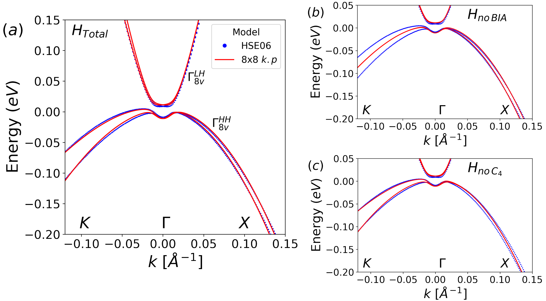
For a better quantitative analysis of the effect of strain and BIA symmetry breaking terms on the sub-band splitting in our \ceHgTe system, we fit a perturbed 88 Kane Hamiltonian (Eqn.(2.5)) to the DFT band structure along the -- path (Fig. 2(a)). To study the effects of the strain term on the energy eigenvalues we ignore , thus our model Hamiltonian can be described as . To provide a clearer explanation of the band splitting observed in the heavy hole (HH) bands (i.e., the bands associated with ), we make the following assumptions to simplify the blocks of along the crystallographic directions of interest. In our \ceHgTe system, we consider the in-plane strain to be isotropic, hence and . Thus the expressions in Eqns (2.2) and (2.2) are simplified to
| (3.1) |
| (3.2) |
In the absence of BIA and strain terms there is no splitting between the energy bands, and the eigenvalues of are pairwise spin-degenerate. Therefore, to accurately gauge the effect of the strain terms on the band splitting between bands, we must apply the formalism of degenerate perturbation theory.
Let and be an orthonormal basis constructed from the normalized eigenstates of corresponding to the degenerate bands. On rewriting in terms of and after diagonalization, we obtain the the eigenvalues and , from which we can define a parameter: , which represents splitting between the bands. Calculating the value of at a point along a particular crystallographic direction gives us an idea of whether the splitting observed along that path is significant or negligible.
Along the - direction, , so Eqns. (3.1) and (3.2) can be written as
| (3.3) |
| (3.4) |
For example, at we obtain the eigenvalues and , which results in . Thus, the calculated value of along this direction is large enough to induce a noticeable splitting between the . This implies that the strain terms will contribute significantly to band splitting along the - direction.
Along the - and - direction, , where and , respectively, we do not consider as (Eqns. (3.1) and (3.2)). Thus, we obtain the expressions
| (3.5) |
| (3.6) |
We again consider the case of , but now along the - path. In this case, , and . The value of is rather small, making the energy bands indistinguishable. This implies that the strain terms induce negligible splitting between the bands along the - and - directions.
To confirm the above hypothesis we fit to our DFT results along the -- path (Fig. 2(b)). We find that along the - direction, the splitting is primarily induced by the strain terms, whereas in the - direction, negligible splitting is induced by the strain terms. The same result is obtained when we fit to our DFT band structure calculated along the -- path (Fig. 4(c)).
Now, to study the effects of BIA on the energy eigenvalues we ignore , thus our model Hamiltonian is . To gauge the effects of on the band splitting, we again apply the degenerate perturbation theory using . Like the case of strain terms, we again define a parameter which describes the splitting induced by BIA and is equivalent to the difference between the eigenvalues of represented in terms of the basis.
For on the - path, we find that the eigenvalues , and . Since this value is negligible, the bands are indistinguishable. We can thus confirm that the splitting produced along this path is primarily due to the strain terms, owing to the much larger value of .
From our prior analysis of the strain terms, it becomes evident that the BIA of the \ceHgTe lattice is responsible for band splitting along paths where the splitting induced by the terms is negligible. This hypothesis is strongly supported by our calculated eigenvalues at along the - direction: , and . Owing to the large value of as compared to , we confirm that the BIA terms are primarily responsible for band splitting. To confirm our hypothesis, we fit to our DFT data along the -- path (Fig. 2(c)) and find that the splitting induced by BIA terms along the - direction is indeed much greater than the strain-induced splitting, thus making it the dominant cause of band splitting. The same can also be stated for the - direction (Fig. 4(c)). This fit also confirms that the splitting along the - direction results primarily due to , as produces negligible band splitting, rendering the bands indistinguishable.
3.2 Band splitting in the plane
Prior to this study, the strain terms were not included in models that discussed the band structure of strained \ceHgTe [9, 12, 8, 17, 18, 19, 20, 10]. This can be attributed to the lack of experimental evidence of strain-induced sub-band splitting in \ceHgTe prior to [13] and the lower magnitude of band splitting induced by strain.
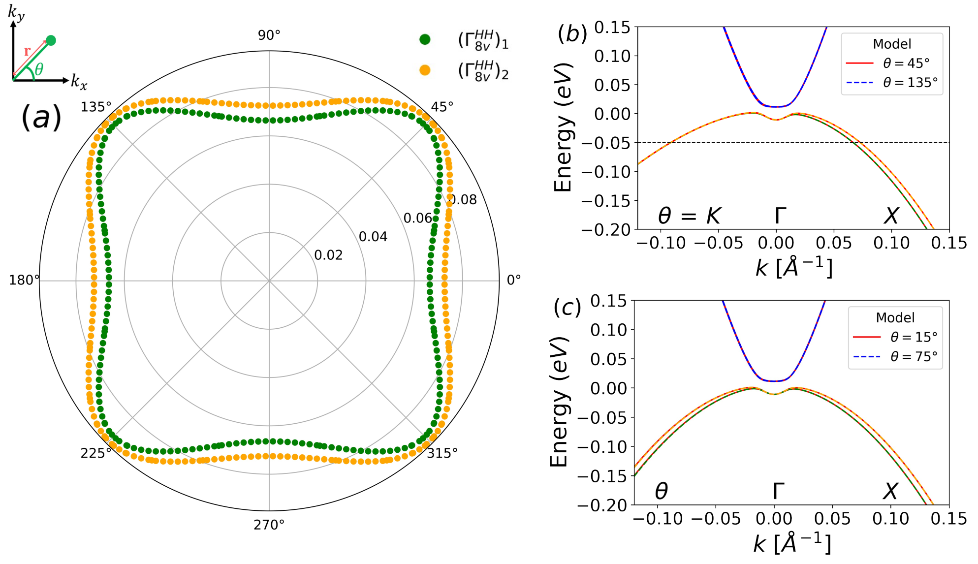
To better understand the behaviour of the band splitting induced by strain term (in the absence of BIA), we plot the isoenergetic surface at eV of the hybridized bands: and obtained using in radial coordinates i.e (, ) on the = 0 plane. The resultant band dispersions obtained from have been depicted in Fig. 3(a). This dispersion reveals that The magnitude of band splitting is maximum along the i.e the axis (-). As we move towards i.e the - direction, the splitting between the bands decreases and is minimum at . As we move away from , the splitting again increases and again becomes maximum at . This implies that the band splitting induced by the strain term in the plane is consistent with the four-fold rotational symmetry of the \ceHgTe lattice in the same plane. We verify this observation by comparing the electronic band structure at and , which we find to be identical (Fig. 3(b)). The resultant dispersion is also symmetric about the axis i.e the - direction. This can be verified by comparing the electronic band structure at and , which we also find to be identical (Fig. 3(c)).
3.3 Competition between strain and BIA terms to induce band splitting
The strain term has been used previously to describe the offset in quantum resonance energies obtained from cyclotron spectra in strained \@slowromancapiii@-\@slowromancapv@ semiconductors such as InSb [36, 37]. However, these studies have not established how the term would influence the band splitting in the presence of BIA as well as the varying magnitude of -induced sub-band splitting along various crystallographic directions. Furthermore, these studies utilized band structures calculated by the primitive empirical pseudopotential method with no experimental input. Here, we probe the interplay between the strain and BIA terms by fitting our model to the band structure calculated along different -paths using DFT to understand when each of these terms dominates the band splitting mechanism.
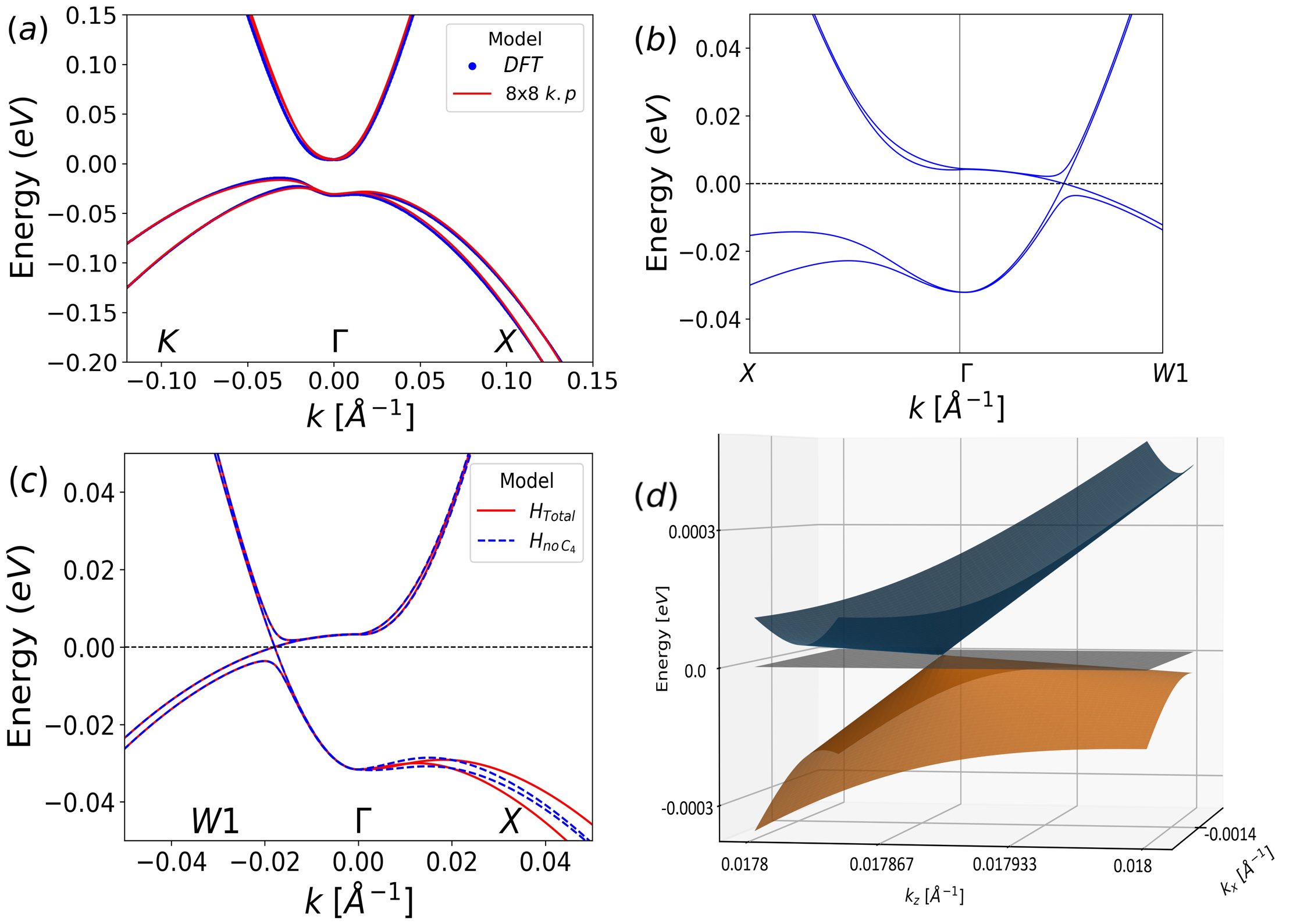
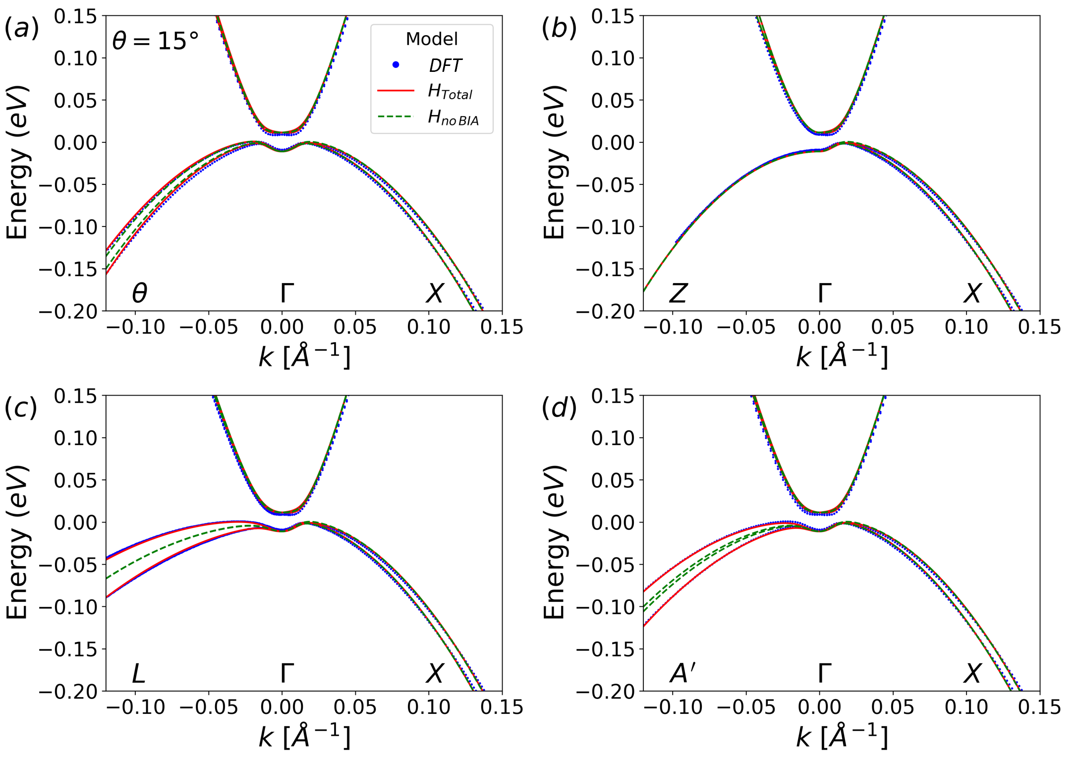
To gauge the competition between the strain and BIA terms in inducing band splitting of the bands, we fit (includes terms but no BIA) and (includes both and BIA terms) to our DFT electronic band structure (Fig. 4). We summarize the competition between the and BIA terms by considering four cases, namely: an arbitrary path inclined at 15 to the axes, a path along the axes, the high symmetry - direction and an arbitrary path inclined at 57.65 to the direction whose in plane projection forms an angle of 31.64 with the axis. In the first case (Fig. 4(a)) we find that a significant amount of the band splitting can be attributed to the strain terms as compared to the BIA terms. The dominance of terms in the band splitting phenomenon arises due to the proximity of this path to the axes where band splitting arises primarily due to the strain terms. Along the direction (Fig. 4(b)) there is no band splitting. Though one would normally attribute splitting along this direction to the terms, the terms affiliated with the direction cancel out due to the isotropic nature of strain in the plane, resulting in no splitting. The case of the - high symmetry path (Fig. 4(c)) is identical to the - path as the band splitting arises completely due to the BIA terms, the cause of which has been discussed in Section 3.1. On considering an arbitrary path - (Fig. 4(d)) we find that the strain terms have a negligible contribution to the band splitting whereas the BIA terms have a substantial contribution to the band splitting. It can be estimated that the proximity of - to the - high symmetry path is what causes the BIA terms to dominate the band splitting phenomenon.
3.4 The Weyl semimetal state
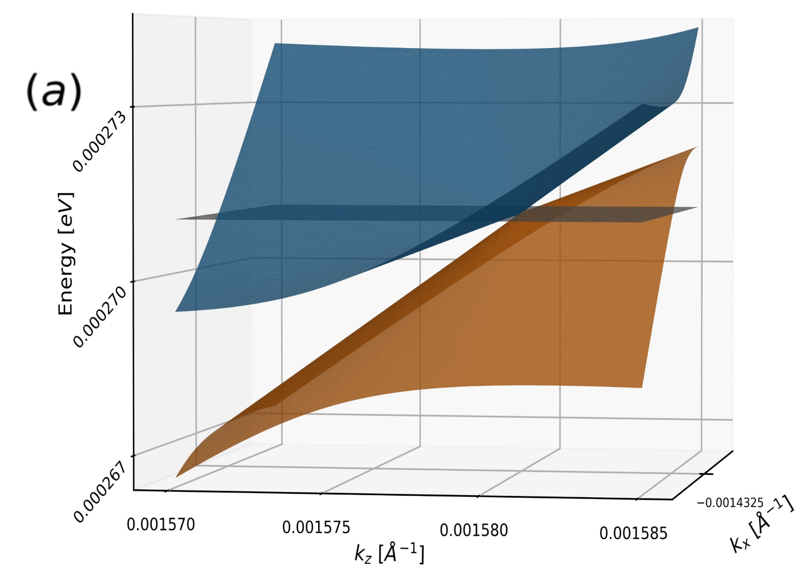
Prior work [9, 38, 10] has demonstrated that \ceHgTe can be coaxed to attain a Weyl semimetal state when compressed, where the Weyl cones are located in the and plane. Here, we demonstrate that including the strain terms in our model Hamiltonian allows us to obtain a robust Weyl semimetal state, with Weyl point locations in the plane at the Fermi level that are consistent with those obtained in the absence of these terms (see Table 2). To determine the position of Weyl points using our model Hamiltonian , we first fit our model Hamiltonian to our DFT electronic band structure calculated along the -- path. We then use our fit to the DFT data (Fig. 5(a)) to find the location of Weyl points. A minimal change in the position of Weyl points is observed for and (no strain terms), which implies that the inclusion of the strain terms have no effect on the Weyl semimetal state. Therefore, models that ignore the strain terms are still suitable to probe the Weyl semimetal phase. However, on comparing the Weyl point location obtained by our model Hamiltonian to that obtained by Wannier interpolation of the DFT band structure, we find that the WP location predicted by our functional does not lie in the plane. This can be attributed to the loss of symmetries during the Wannier interpolation of the DFT band structure.
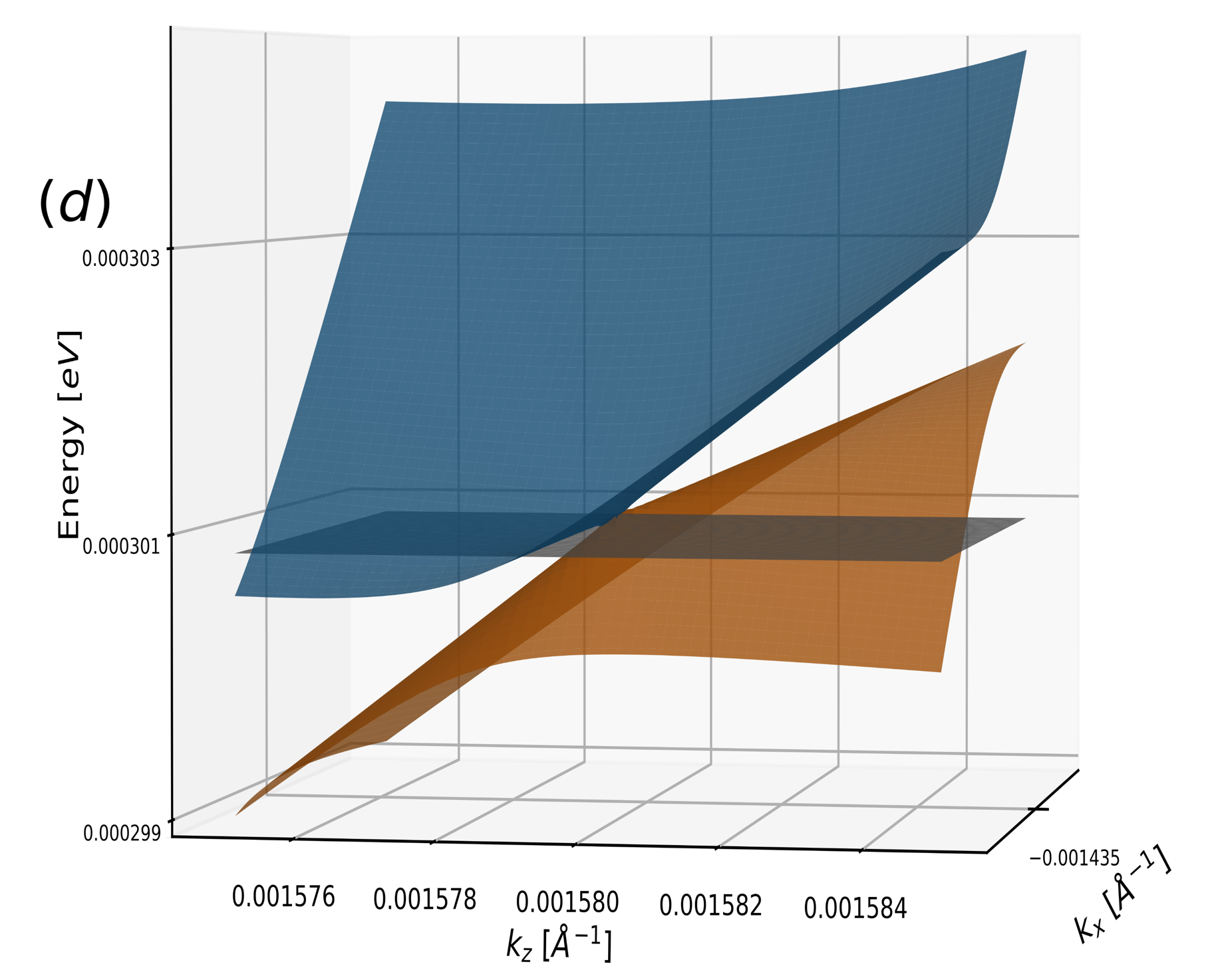
Next, we study the change in the \ceHgTe band structure across the compressive strain regime using by extrapolating our Weyl semimetal fit parameters obtained at = % to other strain values. This results in three distinct strain regions that host a Weyl semimetal state. To classify the Weyl semimetal state we use one of the methods described in [39], wherein we plot the 3D band structure in the plane and probe Weyl band crossing at the Fermi surface for charge pockets. The type-2 Weyl semimetal state can be characterized by a significant tilt of the Weyl cones such that they cut the Fermi surface (or isoenergetic surface of the Weyl point) to form charge pockets. If there is a considerable tilt of the Weyl cones, but no charge pockets at the Fermi surface, the phase is classified as a tilted type-1 Weyl semimetal. The complete absence of a tilt of Weyl cones implies that the phase is an ideal type-1 Weyl semimetal.
The high strain region: At large compressive strains such as % we observe a tilted type-1 Weyl semimetal state [21] with and without terms (Fig. 5(c)). This is in stark contrast to prior work [9, 10] that predicts an ideal type-1 Weyl semimetal (no tilt). Fermi level analysis of the 3D band structure (Fig. 5(d)) confirms the presence of a tilted type-1 Weyl semimetal due to the absence of charge pockets and considerable inclination of the Weyl cone. Literature [21] that has studied the Weyl semimetal state in various materials has demonstrated an increase in the Berry curvature dipole of a system with the tilting of Weyl cones. Since strained \ceHgTe can display a Berry curvature dipole [10], realizing this phase will prove useful for enhancing it for use in future applications. Furthermore, the ability of our model to predict tilted type-1 Weyl cones, makes it useful for studying the superconducting diode effect observed in such tilted Weyl semimetals [22].
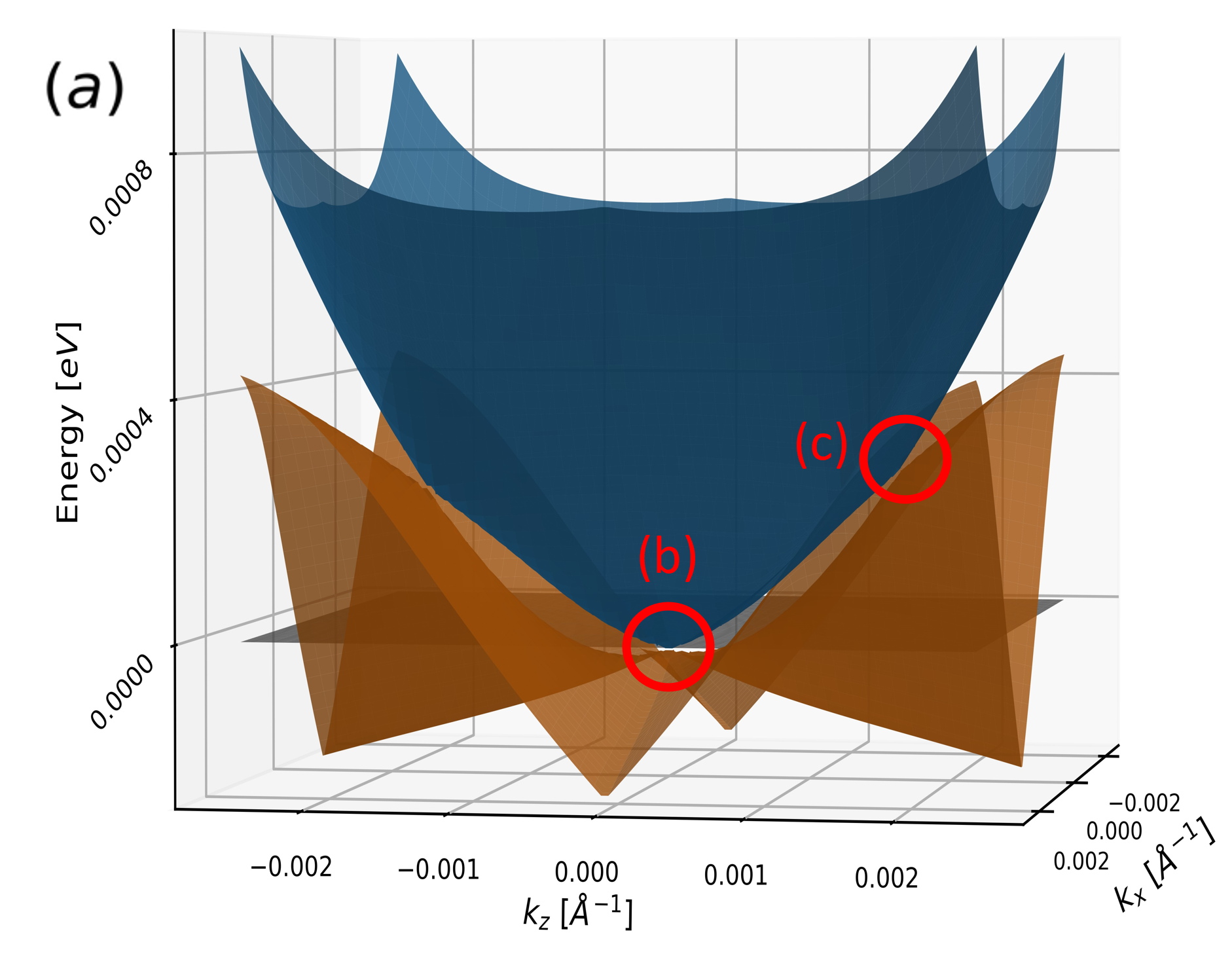
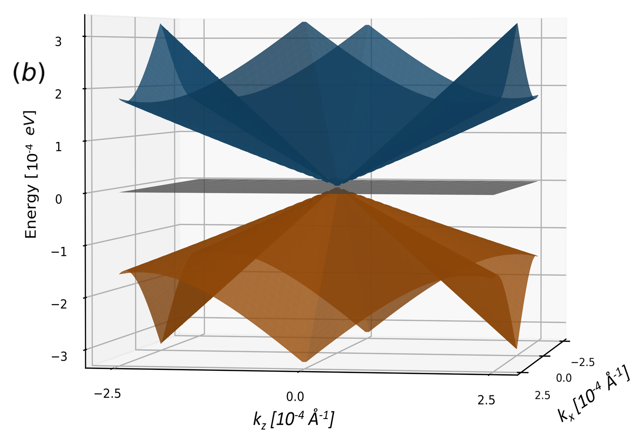
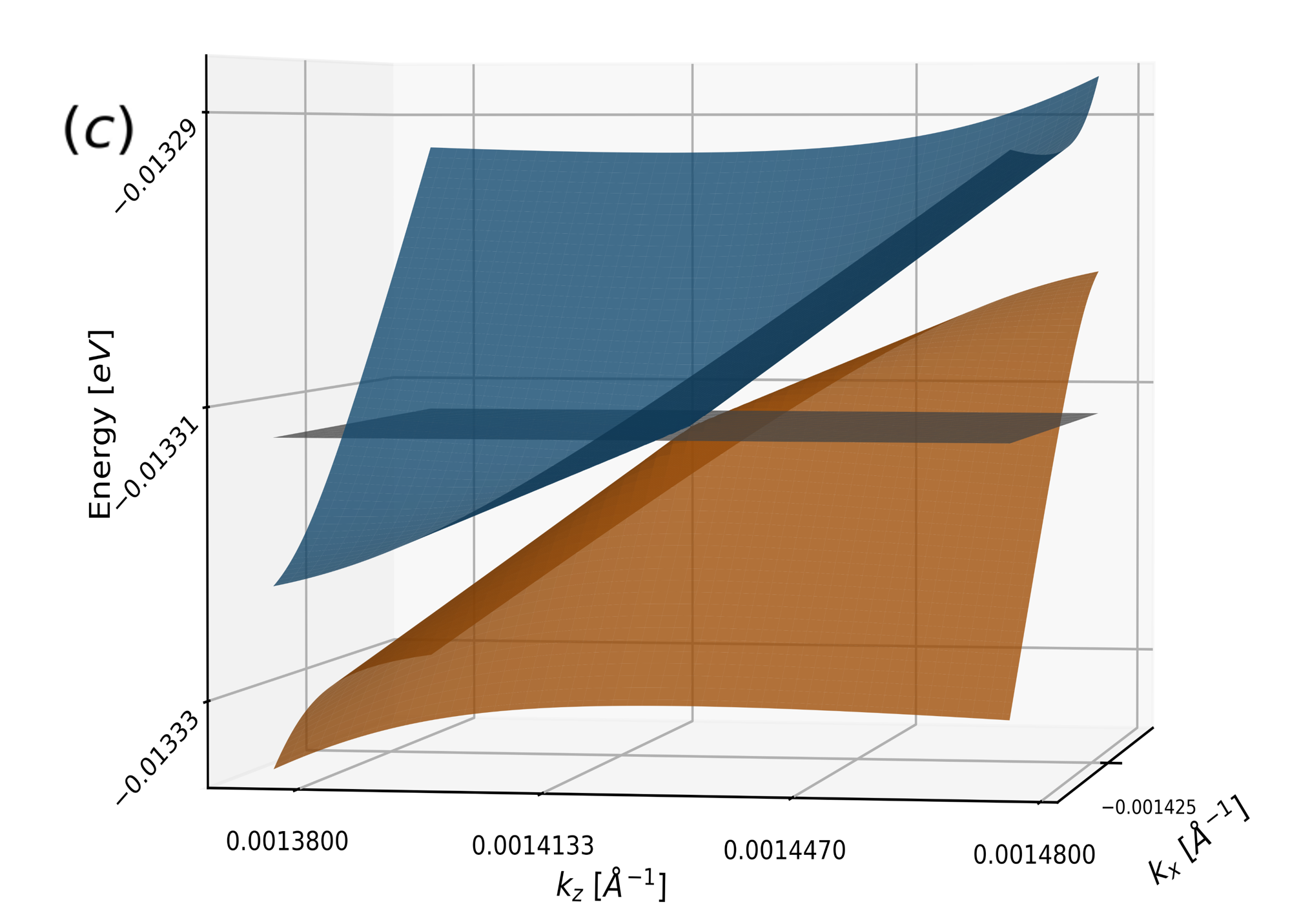
The unstrained (0%) state: In the unstrained state we observe two types of crossings (Fig. 6(a)). The first is centered at the high symmetry -point on the Fermi surface (Fig. 6(b)), whereas the second kind are significantly tilted and lie above the Fermi level (Fig. 6(c)). Previous work [9, 10] has demonstrated the existence of nodal lines that contain Weyl points in the and planes at 0% strain which converge at . This implies that the first crossing is topologically trivial and not a Weyl point. To accurately classify the nature of the second type of band crossing, we construct a surface that is isoenergetic with the observable Weyl points. The presence of charge pockets at the isoenergetic surface implies that unstrained \ceHgTe also hosts a type-2 Weyl semimetal state.
The low strain region: At very small strain, such as % (and %), we observe a substantial increase in the inclination of the Weyl cones in figure 6(d) (see Appendix section D ), as well as the energy of the Weyl points, which now lie above the Fermi level. The significant tilt of the Weyl cones results in charge pockets being observed at their isoenergetic surface implying that the Weyl semimetal state is of type-2.
| Model | () | () | () |
|---|---|---|---|
| DFT-HSE06 | 0.000588 | -0.000270 | 0.009780 |
| 0.001438 | 0.000000 | 0.017871 | |
| 0.001433 | 0.000000 | 0.017844 |
4 Conclusions
We have studied the effects of strain on the sub-band splitting mechanism in the 3D topological insulator \ceHgTe by fitting our model to a state of the art DFT calculations able to quantitatively describe the photoemission spectra. The inclusion of the higher order strain terms in our model, which compete with the intrinsic BIA of the \ceHgTe lattice, is crucial for understanding the sub-band degeneracy breaking and results in a -path specific sub-band splitting phenomenon depending on whether strain or BIA dominates.
We apply our improved model to study the topological phase transition in the Weyl semimetal state. Our model is consistent with the phase diagram predicted in prior research with the exception of the high compressive strain region, where we observe a tilted type-1 Weyl semimetal instead of an ideal type-1 Weyl semimetal. Such a tilted Weyl semimetal state would be suitable for applications that require a Berry curvature dipole which results from this tilt.
Our work provides a more accurate insight as to how the incorporation of symmetry breaking terms such as BIA and into the model Hamiltonian influence the camel’s back formation in the tensile strain phase and the topological phase transition towards a Weyl phase as a function of strain.
Acknowledgements.
We thank Domenico Di Sante for insightful discussions. E.K. acknowledges Laurens W. Molenkamp and Hartmut Buhmann for the hospitality provided at the Physikalisches Institut (EP3), Universität Würzburg, and at the Institute for Topological Insulators. E.K. acknowledges financial support from the German Academic Exchange Service (DAAD) through the WISE program. G.M., P.M.F. and G.P. acknowledge CINECA under the ISCRA initiative. G.M. acknowledges funding by the European Union (ERC, DELIGHT, 101052708). Views and opinions expressed are however those of the author(s) only and do not necessarily reflect those of the European Union or the European Research Council. Neither the European Union nor the granting authority can be held responsible for them. P.M.F. and G.P. thanks the Director and the Computing Network Service of the Laboratori Nazionali del Gran Sasso (LNGS-INFN). This research used resources of the LNGS HPC cluster realised in the framework of Spoke 0 and Spoke 5 of the ICSC project - Centro Nazionale di Ricerca in High Performance Computing, Big Data and Quantum Computing, funded by the NextGenerationEU European initiative through the Italian Ministry of University and Research, PNRR Mission 4, Component 2: Investment 1.4, Project code CN00000013 - CUP I53C21000340006. G.P. acknowledges fundings from the European Union - NextGenerationEU under the Italian Ministry of University and Research (MUR) National Innovation Ecosystem grant ECS00000041 - VITALITY - CUP E13C22001060006. G.S. and W.B. acknowledge financial support from the Deutsche Forschungsgemeinschaft (DFG, German Research Foundation) in the project SFB 1170 ToCoTronics (Project ID 258499086) and in the Würzburg-Dresden Cluster of Excellence on Complexity and Topology in Quantum Matter ct.qmat (EXC 2147, Project ID 390858490).Appendix A Definition of and matrices
has been constructed in terms of the 8 orbital basis mentioned in Section 2.2 and can be described as
| (A.1) |
Each individual block can be expanded as follows,
| (A.2) |
| (A.3) |
| (A.4) |
| (A.5) |
| (A.6) |
where
| (A.7) |
| (A.8) |
| (A.9) |
| (A.10) |
and where , , , and .
represents the valence band maxima, which amounts to about for the TI state and for the Weyl semimetal state. represents the energy gap between the bands and the light hole (LH) bands (i.e, the bands corresponding to ). We find that for the TI state and for the Weyl semimetal state. represents the energy gap between the energy of the HH bands at the point and the bands. It amounts to about and for the topological insulator and Weyl semimetal state, respectively. is related to the free electron mass via the expression
| (A.11) |
where [12].
, and represent the Luttinger parameters. For the TI state, and show negligible variation in their estimated mean values of about and , respectively, whereas the mean value of varies by . Whereas, for the Weyl semimetal state, , and . Here represents the expectation value of the momentum operator with the and orbitals where and can be written as . For our calculations we set .
In the absence of shear strain, can be represented in terms of the same basis as
| (A.12) |
where
| (A.13) |
| (A.14) |
| (A.15) |
| (A.16) |
in which (the trace of the strain tensor), and as we consider the in-plane () strain to be isotropic (i.e ). The coefficients , and are treated as constants throughout our calculations and amount to , and , respectively.
Appendix B Definition of and matrices
The angular momentum matrices, have been constructed in terms of the basis corresponding to the bands.
| (B.1) |
| (B.2) |
| (B.3) |
The matrices, are needed to describe the interactions between the bands and the or the bands, respectively. They can be defined as
| (B.4) |
| (B.5) |
| (B.6) |
Appendix C Definition of the matrix
can be described as
| (C.1) |
where each block can be depicted in terms of the momentum (, , ) and coefficients , , and . Each of the above listed blocks can be described as
| (C.2) |
| (C.3) |
| (C.4) |
| (C.5) |
From our fit to the DFT data in the TI as well as the Weyl semimetal state, we find that , and remain constant with values of about , and , respectively. We find that the mean value , varies by about along different paths in the Brillouin zone for the TI state and is about for the Weyl semimetal state.
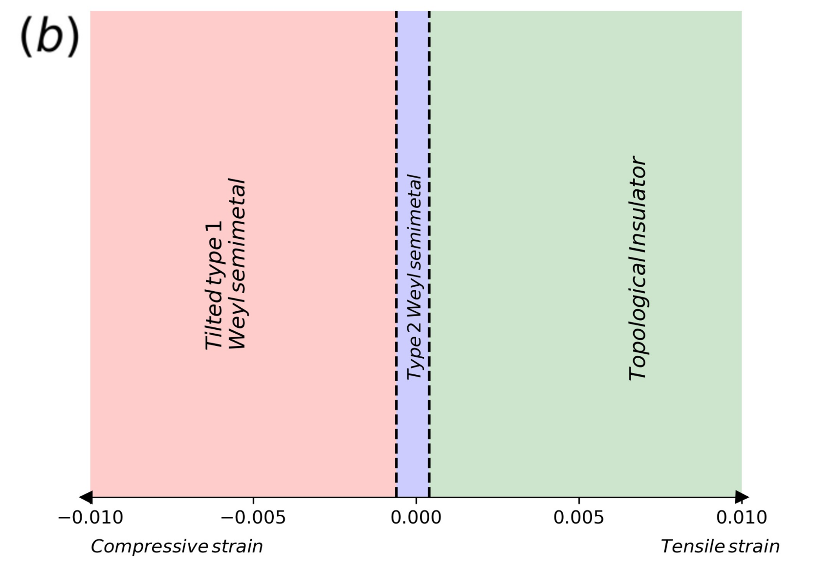
Appendix D The topological phase diagram of \ceHgTe as a function of strain
Based on our study of the evolution of the Weyl semimetal state with strain, we construct a topological phase diagram of \ceHgTe as a function of strain (Fig. S1(b)). Our results, obtained from fitting to the band structure calculated using DFT, are consistent with those predicted in prior work [9, 10], as a result of which we obtain a similar topological phase diagram, with the exception of a tilted type-1 Weyl semimetal instead of an ideal type-1 Weyl semimetal state at large compressive strains. This demonstrates that the inclusion of the strain terms in our model does not change the topology of \ceHgTe.
References
- Kane and Mele [2005] C. L. Kane and E. J. Mele, Phys. Rev. Lett. 95, 146802 (2005).
- Fu et al. [2007] L. Fu, C. L. Kane, and E. J. Mele, Phys. Rev. Lett. 98, 106803 (2007).
- Qi and Zhang [2011] X.-L. Qi and S.-C. Zhang, Rev. Mod. Phys. 83, 1057 (2011).
- Moore and Balents [2007] J. E. Moore and L. Balents, Phys. Rev. B 75, 121306 (2007).
- Hasan and Kane [2010] M. Z. Hasan and C. L. Kane, Rev. Mod. Phys. 82, 3045 (2010).
- König et al. [2007] M. König, S. Wiedmann, C. Brüne, A. Roth, H. Buhmann, L. W. Molenkamp, X.-L. Qi, and S.-C. Zhang, Science 318, 766 (2007) .
- Leubner et al. [2016] P. Leubner, L. Lunczer, C. Brüne, H. Buhmann, and L. W. Molenkamp, Phys. Rev. Lett. 117, 086403 (2016).
- Leubner [2017] P. Leubner, Strain-engineering of the Topological Insulator , doctoralthesis, Universität Würzburg (2017).
- Ruan et al. [2016] J. Ruan, S.-K. Jian, H. Yao, H. Zhang, S.-C. Zhang, and D. Xing, Nat. Commun. 7, 11136 (2016).
- Chen et al. [2019] C. Chen, H. Wang, D. Wang, and H. Zhang, in Spin, Vol. 9 (World Scientific, 2019) p. 1940017.
- Kane [1957] E. O. Kane, J. Phys. Chem. Solids 1, 249 (1957).
- Novik et al. [2005] E. G. Novik, A. Pfeuffer-Jeschke, T. Jungwirth, V. Latussek, C. R. Becker, G. Landwehr, H. Buhmann, and L. W. Molenkamp, Phys. Rev. B 72, 035321 (2005).
- Vidal et al. [2023] R. C. Vidal, G. Marini, L. Lunczer, S. Moser, L. Fürst, J. Issing, C. Jozwiak, A. Bostwick, E. Rotenberg, C. Gould, H. Buhmann, W. Beugeling, G. Sangiovanni, D. Di Sante, G. Profeta, L. W. Molenkamp, H. Bentmann, and F. Reinert, Phys. Rev. B 107, L121102 (2023).
- Trebin et al. [1979] H. R. Trebin, U. Rössler, and R. Ranvaud, Phys. Rev. B 20, 686 (1979).
- Dresselhaus [1955] G. Dresselhaus, Phys. Rev. 100, 580 (1955).
- Semenikhin et al. [2007] I. Semenikhin, A. Zakharova, K. Nilsson, and K.-A. Chao, Phys. Rev. B 76, 035335 (2007).
- Mahler et al. [2021] D. M. Mahler, V. L. Müller, C. Thienel, J. Wiedenmann, W. Beugeling, H. Buhmann, and L. W. Molenkamp, Nano Lett. 21, 9869 (2021).
- Zhang et al. [2001] X. C. Zhang, A. Pfeuffer-Jeschke, K. Ortner, V. Hock, H. Buhmann, C. R. Becker, and G. Landwehr, Phys. Rev. B 63, 245305 (2001).
- Becker et al. [2000] C. R. Becker, V. Latussek, A. Pfeuffer-Jeschke, G. Landwehr, and L. W. Molenkamp, Phys. Rev. B 62, 10353 (2000).
- Zhang et al. [2004] X. C. Zhang, K. Ortner, A. Pfeuffer-Jeschke, C. R. Becker, and G. Landwehr, Phys. Rev. B 69, 115340 (2004).
- Zhang et al. [2018] Y. Zhang, Y. Sun, and B. Yan, Phys. Rev. B 97, 041101 (2018).
- Chen et al. [2024] K. Chen, B. Karki, and P. Hosur, Phys. Rev. B 109, 064511 (2024).
- Blöchl [1994] P. E. Blöchl, Phys. Rev. B 50, 17953 (1994).
- Kresse and Joubert [1999] G. Kresse and D. Joubert, Phys. Rev. B 59, 1758 (1999).
- Kresse and Hafner [1993] G. Kresse and J. Hafner, Phys. Rev. B 47, 558 (1993).
- Kresse and Hafner [1994] G. Kresse and J. Hafner, Phys. Rev. B 49, 14251 (1994).
- Kresse and Furthmüller [1996] G. Kresse and J. Furthmüller, Comput. Mater. Sci. 6, 15 (1996).
- Kresse and Furthmüller [1996] G. Kresse and J. Furthmüller, Phys. Rev. B 54, 11169 (1996).
- Berding et al. [2000] M. A. Berding, W. D. Nix, D. R. Rhiger, S. Sen, and A. Sher, J. Electron. Mater. 29, 676 (2000).
- Krukau et al. [2006] A. V. Krukau, O. A. Vydrov, A. F. Izmaylov, and G. E. Scuseria, J. Chem. Phys 125, 224106 (2006).
- Wu et al. [2018] Q. Wu, S. Zhang, H.-F. Song, M. Troyer, and A. A. Soluyanov, Comput. Phys. Commun. 224, 405 (2018).
- Pizzi et al. [2020] G. Pizzi, V. Vitale, R. Arita, S. Blügel, F. Freimuth, G. Géranton, M. Gibertini, D. Gresch, C. Johnson, T. Koretsune, J. Ibañez-Azpiroz, H. Lee, J.-M. Lihm, D. Marchand, A. Marrazzo, Y. Mokrousov, J. I. Mustafa, Y. Nohara, Y. Nomura, L. Paulatto, S. Poncé, T. Ponweiser, J. Qiao, F. Thöle, S. S. Tsirkin, M. Wierzbowska, N. Marzari, D. Vanderbilt, I. Souza, A. A. Mostofi, and J. R. Yates, Journal of Physics: Condensed Matter 32, 165902 (2020).
- Winkler [2003] R. Winkler, Spin-orbit coupling effects in two-dimensional electron and hole systems, Vol. 191 (Springer, 2003).
- Alper and Saunders [1967] T. Alper and G. Saunders, Journal of Physics and Chemistry of Solids 28, 1637 (1967).
- Bir et al. [1974] G. L. Bir, G. E. Pikus, and D. Louvish, Symmetry and strain-induced effects in semiconductors, Vol. 484 (Wiley New York, 1974).
- Ranvaud et al. [1979] R. Ranvaud, H.-R. Trebin, U. Rössler, and F. H. Pollak, Phys. Rev. B 20, 701 (1979).
- Silver et al. [1992] M. Silver, W. Batty, A. Ghiti, and E. O’Reilly, Phys. Rev. B 46, 6781 (1992).
- Mahler et al. [2019] D. M. Mahler, J.-B. Mayer, P. Leubner, L. Lunczer, D. Di Sante, G. Sangiovanni, R. Thomale, E. M. Hankiewicz, H. Buhmann, C. Gould, and L. W. Molenkamp, Phys. Rev. X 9, 031034 (2019).
- Li et al. [2017] P. Li, Y. Wen, X. He, Q. Zhang, C. Xia, Z.-M. Yu, S. A. Yang, Z. Zhu, H. N. Alshareef, and X.-X. Zhang, Nat. Commun. 8, 2150 (2017).