Harmonizing Attention: Training-free Texture-aware Geometry Transfer
Abstract
Extracting geometry features from photographic images independently of surface texture and transferring them onto different materials remains a complex challenge. In this study, we introduce Harmonizing Attention, a novel training-free approach that leverages diffusion models for texture-aware geometry transfer. Our method employs a simple yet effective modification of self-attention layers, allowing the model to query information from multiple reference images within these layers. This mechanism is seamlessly integrated into the inversion process as Texture-aligning Attention and into the generation process as Geometry-aligning Attention. This dual-attention approach ensures the effective capture and transfer of material-independent geometry features while maintaining material-specific textural continuity, all without the need for model fine-tuning.
![[Uncaptioned image]](/html/2408.10846/assets/figures/eyecatch3.png)
1 Introduction
In computer vision, image harmonization is the task of seamlessly integrating a foreground object from one image into the background of another to produce a cohesive composite. A significant challenge is achieving visual harmony by adjusting the foreground’s appearance to align with the background. Traditional methods [1, 2, 3, 4, 5, 6, 7, 8, 9, 10] have primarily addressed image harmonization by focusing on color and illumination adjustments.
Recent advances in deep learning and diffusion models [11, 12, 13, 14, 15, 16, 17, 18, 19, 20, 21] have enabled sophisticated image composition and harmonization, as exemplified by ObjectStitch [20] and TF-ICON [21]. These methods primarily focus on style transfer, encompassing a broad range of attributes such as color schemes, brushstrokes, textures, and patterns that collectively determine an image’s visual appearance. However, the selective transfer of geometrical features—which we term “geometry” in this paper—such as holes, cracks, droplets, and dents from one material to another, independently of material-specific surface texture (e.g., wood grain or fabric weave), remains a complex challenge. To the best of our knowledge, existing techniques have not successfully addressed this issue. Such geometry transfer is crucial for creating realistic and aesthetically pleasing composite images, particularly in applications requiring the integration of complex textures from different materials, like transferring wood hole geometry onto metal surfaces. Traditional and recent deep-learning-based image harmonization methods struggle with geometry transfer due to their focus on color, illumination, and style adjustments of the object itself. This limitation highlights the need for a fundamentally different approach that can effectively decouple geometry from material-specific textures in image harmonization tasks.
To address this challenge, we propose Harmonizing Attention, a novel training-free diffusion-model-based approach for texture-aware geometry transfer. The key aspect of this method is a custom attention mechanism comprising Texture-aligning Attention and Geometry-preserving Attention, enabling reference to both source geometry and target texture information. By replacing the self-attention layers in the diffusion model with these custom attention layers during inversion and generation, we successfully incorporate geometry and texture from different images, as demonstrated in Fig. 1. Notably, since the Harmonizing Attention framework leverages pretrained diffusion models to perform geometry transfer, it requires neither model tuning nor prompt exploration for each dataset.
Our contributions are summarized as follows:
-
1.
We introduce texture-aware geometry transfer, a novel approach for integrating geometry details from different materials into cohesive composite images.
-
2.
We develop Harmonizing Attention, a training-free mechanism enabling models to query information from multiple reference images within self-attention blocks, effectively capturing and transferring material-independent geometry while preserving material-specific textures.
-
3.
Our experiments demonstrate that Harmonizing Attention produces more harmonious and realistic composite images compared with existing techniques.
2 Related Work
Image Harmonization.
Conventionally, image harmonization [1, 2, 3, 4, 5, 6, 7, 8, 9, 10] has focused on color-to-color transformations to match visual appearances. These methods can be further divided into non-linear transformations [7, 9] and linear transformations [3, 6, 10]. Recently, deep-learning-enabled image harmonization emerged [11, 12, 13, 14, 15, 16, 17, 18, 19] and more recently diffusion-model-based harmonization techniques [20, 21] have been developed. One notable example is TF-ICON [21], which equips attention-based text-to-image diffusion models for image harmonization, enabling cross-domain image-guided composition.
Paintely Image Harmonization.
In the context of image harmonization, a similar task called painterly image harmonization [22, 23, 24, 25, 26, 27] has been studied, and it might be another promising candidate technique for geometry transfer. The painterly image harmonization technique integrates a photographic foreground into an artistic background, resulting in a visually coherent painting. PHDiffusion [28] represents a significant pivot by adapting the GAN framework (PHDNet [22]) to a diffusion model with an adaptive encoder. Furthermore, TF-GPH [29], which utilizes an image-wise attention-sharing mechanism for general painterly harmonization, is proposed for training-free general painterly harmonization and provides flexible options for attention-based image editing methods.
3 Methods
Our objective is to synthesize an image that seamlessly integrates surface geometry information from a source image into a target background image . This integration is guided by a 0-1-valued foreground mask , preserving the geometry of while maintaining textural continuity with , independently of the source’s original texture, where denotes the Hadamard (elementwise) product. To achieve this, we propose a novel framework called Harmonizing Attention. As illustrated in Fig. 2, this framework leverages Stable Diffusion (SD) [30] and encompasses both inversion and generation processes. The key aspect of our approach is modifying self-attention computation during both inversion and generation to query additional information from and , enabling a more coherent and context-aware transfer process. Furthermore, to enhance textural continuity within the target region, we utilize the SD inpainting model rather than the text-to-image model.
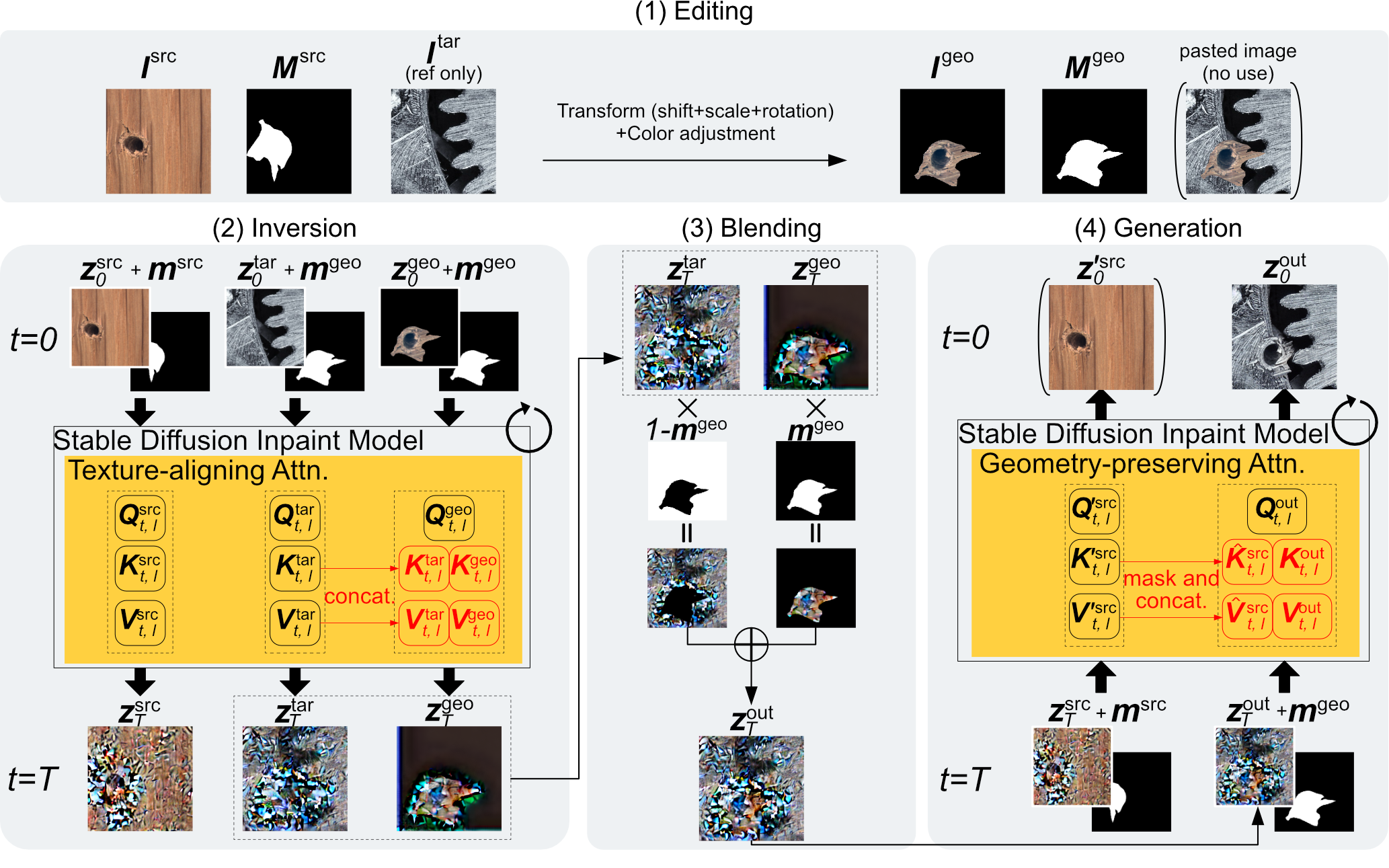
Editing.
The initial stage of our framework involves preparation of a geometry image , which serves as a cornerstone for the subsequent image generation process. A geometry image is simply an image patch of a source image cropped by a 0-1 source mask , with affine transformations (shifting, scaling, and rotation) according to the user’s needs, as well as the color adjustment described below (see the uppermost panel in Fig. 2). The ultimate objective of our framework is to seamlessly synthesize this geometry image with the target image.
The color adjustment of the geometry image plays a crucial role in that it facilitates the inversion process to work properly. By aligning the color profile of the source region with that of the target image, we expect that it will be easier to bring the geometry image closer to the visual domain of the target through the inversion procedure. Because the geometry information is expressed through localized color differences rather than absolute values, we employ a simple uniform color shift, although more sophisticated color adjustment methods would also be feasible. Specifically, we compute this shift by calculating the difference between two color averages: (1) , which is the mean color of the source image within the region formed by subtracting the source mask from its dilated version (i.e., the boundary of the complementary mask in mathematical morphology, where the complementary mask of a mask is defined by replacing 0 with 1 and vice versa in ); (2) , which is the mean color of the target image within an analogous region, defined by subtracting the transplantation-area mask from its dilated version, where the transplantation-area mask defines the transplantation region in the target-image coordinate. This process is represented by the following equation:
| (1) |
where represent the pixel values at coordinates in the image before and after color adjustment, respectively. , value of at coordinates , becomes 1 only if the pixel in the target image is within the transplantation region. Equation (1) then shows that the color adjustment is done only within the transplantation region. The scalar parameter controls the strength of the color adjustment. It is anticipated that employing a small value of would result in inadequate integration of the transplantation region with the target image, while a large value of is expected to compromise the integrity of the source geometry.
Inversion.
The geometry image inherently retains substantial textural information from the source image. Consequently, a direct pasting of the geometry image onto the target image (“pasted image” in Fig. 2) may result in textural discontinuities at the boundaries of in the final output. To address this issue, our objective here is to derive a latent representation that effectively translates the geometry image into the visual domain of the target image through inversion. This domain-shifted latent representation facilitates seamless blending within the latent space, thereby enabling a more naturalistic geometry transplantation. It should be noted that since we leverage SD, the diffusion process operates in the latent space encoded by the variational autoencoder (VAE) instead of the pixel space.
To achieve this, we simultaneously invert the geometry and target images by Denoising Diffusion Implicit Models (DDIM) inversion [31], with replacing self-attention for the geometry image with a novel attention computation which we call Texture-aligning Attention, which additionally incorporates target image information. Let denote the latent representations in the VAE-encoded space, where specific instances will be distinguished by appropriate subscripts in the subsequent discussion. The standard self-attention computation is formulated as:
| (2) |
where denotes the functional representation of self-attention computation, where and denote the dimension of the latent space and the transposition of a matrix, respectively, and where , , and represent the query, key, and value, respectively, all computed from the latents corresponding to the same image. Note that the diffusion step and the layer index are described in Fig. 2, but omitted here for readability. To align the source image domain with the target image domain, we replace the self-attention computation in the inversion of the geometry image with the following formula:
| (3) |
where denotes Texture-aligning Attention, and where the superscripts and denote whether the respective , , and are computed from the geometry image feature map or the target image feature map . As previously elucidated, the geometry image preserves the relative color variations associated with surface geometry through the color adjustment, while simultaneously approximating the visual characteristics of the target image. Consequently, by retaining both the conventional self-attention key () and value () alongside their counterparts derived from the target image ( and ), we anticipate a synergistic effect. This dual-source attention mechanism is expected to efficiently facilitate both geometry preservation and material transformation during the inversion process. A noisy latent representation of the geometry image is then obtained as a result of iterations of the inversion step using this custom attention.
Inversion of the source image and the target image is performed independently, employing the standard self-attention mechanism without any modifications. The resulting noisy latent representations and are then stored for subsequent use in the generation stage and in the blending stage, respectively.
Blending.
Utilizing the latent representations obtained in the inversion stage, in the blending stage (see the lower-middle panel in Fig. 2) we perform a latent-space blending between the geometry and target images. Let be the target mask resized to the latent space. The blended latent representation to be used for generating a synthesized image is computed from the latents and for the geometry and target images at diffusion step as follows:
| (4) |
where denotes the complementary mask of , defined by replacing 0 with 1 and vice versa in .
Generation.
In the generation stage (see the lower-right panel in Fig. 2), we obtain the final output image by denoising the blended latent code synthesized in the blending stage. Although we initialize the generation process with the latents that explicitly incorporate a portion of the source image, it turns out that applying standard denoising procedures may potentially result in the undesirable removal of the transplanted content along with the noise, leading to the loss of the geometry.
To address this challenge, we introduce a novel attention computation named Geometry-preserving Attention. Specifically, we concurrently perform denoising on the source image latent representation obtained during the inversion stage and replace the self-attention computation for the blended latent representation with Geometry-preserving Attention by augmenting the key and value components with information derived from the source image. The process is formally expressed by the following equation:
| (5) |
| (6) |
| (7) |
Here, represents the functional form of the Geometry-preserving Attention. The superscripts and denote that the corresponding variables are associated with the or , respectively. It is important to note that and are used instead of and to distinguish them from the keys and values used during the inversion process. and denote the height and width of the latent feature map , represents the source mask resized to the latent space, and represents -th element of it.
4 Experiments
4.1 Setup
We use the publicly available SD inpainting model checkpoint on HuggingFace111https://huggingface.co/runwayml/stable-diffusion-inpainting as the backbone network. For our experiments, both source image and target image are cropped to a uniform size of pixels. When performing color adjustment as expressed in Eq. 1, we set the scalar parameter to . We set the number of diffusion steps to and employ the DDIM sampler for both the inversion and generation processes, with no prompt input (i.e., an empty string is used) in either phase.
During the inversion phase, we leverage the insights from Garibi et al. [32], which demonstrates that iterative inversion sampling at each diffusion step enhances inversion accuracy. Specifically, we perform 5 sampling iterations per diffusion step in the inversion procedure.
4.2 Datasets and Metrics
We use images from MVTec AD [33, 34] and Pixabay222https://pixabay.com/ in our experiments. For the quantitative evaluation, we employ the following three metrics: LPIPS[35], CLIP[36], and DISTS[37], since metrics specifically tailored for geometry transfer do not currently exist. These established metrics allow us to assess our method’s performance in terms of image harmonization, and compare ours with existing methods. Each metric is evaluated against both the composite image background (denoted , , and ) and the local region of the stretched and harmonized image (denoted , , and ). Here, (bg) and (fg) refer to background and foreground, respectively. It is noteworthy that LPIPS and CLIP have previously been used as evaluation metrics in the existing literature[21, 29]. A total of 150 generated images are used for the quantitative performance evaluation, consisting of 10 composite foreground images and 15 background images, resulting in 150 combinations. Scores are calculated for each method, and the averages of the scores are presented.
4.3 Baselines
For comparison, we select four diffusion-model-based methods, including two image harmonization methods PHDiffusion [28] and TF-GPH [29], one image composition method TF-ICON [21], and one image editing method Paint by Example [38]. Since our Harmonizing Attention does not require prompts, we manually set suitable prompts for generating each sample with TF-ICON. For all methods, we use the default or recommended hyperparameters.
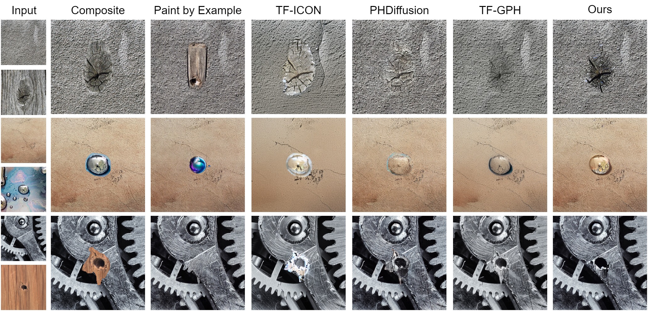
4.4 Qualitative Comparison
We present a qualitative comparison of our proposed method, Harmonizing Attention, with four existing techniques: Paint by Example [38], TF-ICON [21], PHDiffusion [28], and TF-GPH [29]. Paint by Example and TF-ICON struggled with consistent texturing and maintaining original geometries. PHDiffusion showed better texture preservation but struggled with accurate geometry transfer. TF-GPH achieved a balance between texture and geometry alignment compared with previous methods, but still showed subtle texture inconsistencies and degradation of geometric properties upon closer inspection.
In contrast, our proposed method excelled in several critical aspects of image harmonization. It preserved the geometry and structural details of foreground objects with high fidelity. Simultaneously, it successfully adapted the texture and material properties to seamlessly match the background. This dual capability resulted in the most natural and realistic geometry integration across various scenarios, from textured surfaces such as wood to complex materials like metal parts.
User Study
To further compare the apparent quality of each technique, we conducted a user study with 105 participants from CrowdWorks333https://crowdworks.jp. Participants rated 15 images, shown in Fig. 3, on a scale from 1 to 5 (1 being the worst and 5 being the best) on the basis of the following criteria: background preservation (referred to as Quality Of Background, QOB), foreground preservation (referred to as Quality Of Foreground, QOF), and seamless composition (referred to as Quality Of Composition, QOC). Each qualitative rating score was calculated by applying weights to each response choice (5 for the best, 4, 3, 2, and 1 for the worst), and averaging all the responses.
The results are listed in Table 1. Our method consistently outperformed existing methods across all evaluated metrics. The consistent superiority across these different metrics demonstrates the ability of our method to produce high-quality harmonized images with improved boundary definition, improved feature representation, and better overall content coherence compared with the existing techniques.
| Method | QOB | QOF | QOC |
|---|---|---|---|
| Paint by Example | 3.11 | 1.69 | 2.44 |
| TF-ICON | 2.41 | 2.40 | 2.38 |
| PHDiffusion | 3.10 | 2.64 | 3.26 |
| TF-GPH | 3.12 | 2.79 | 3.40 |
| Ours | 3.44 | 2.96 | 3.56 |
4.5 Quantitative Comparison
We conducted a comprehensive quantitative evaluation to assess our method’s performance against state-of-the-art approaches for geometry composition in target background images. Table 2 presents results across multiple metrics, including LPIPS, CLIP, and DISTS, for both background and foreground components. Our method achieved the lowest score of 0.266 and score of 0.179, indicating superior preservation of background structural integrity. Furthermore, ours excelled in foreground semantic consistency, evidenced by the highest score of 91.352. While PHDiffusion and TF-GPH marginally outperformed ours on and respectively, our method maintained competitive scores across all metrics. This balanced performance, particularly our excellence in semantic preservation coupled with strong perceptual and structural similarity scores, suggests the effectiveness of our approach in achieving harmonious image composites. These results collectively demonstrate our method’s advancement of the state-of-the-art in image harmonization across multiple dimensions of visual quality.
| Method | ||||||
|---|---|---|---|---|---|---|
| Paint By Example [38] | 0.424 | 0.273 | 70.694 | 84.348 | 0.256 | 0.241 |
| TF-ICON [21] | 0.434 | 0.392 | 69.470 | 81.422 | 0.309 | 0.315 |
| PHDiffusion [28] | 0.408 | 0.255 | 73.624 | 84.879 | 0.276 | 0.196 |
| TF-GPH [29] | 0.324 | 0.252 | 71.234 | 86.936 | 0.223 | 0.237 |
| Ours | 0.266 | 0.255 | 68.180 | 91.352 | 0.179 | 0.250 |
4.6 Ablation Studies
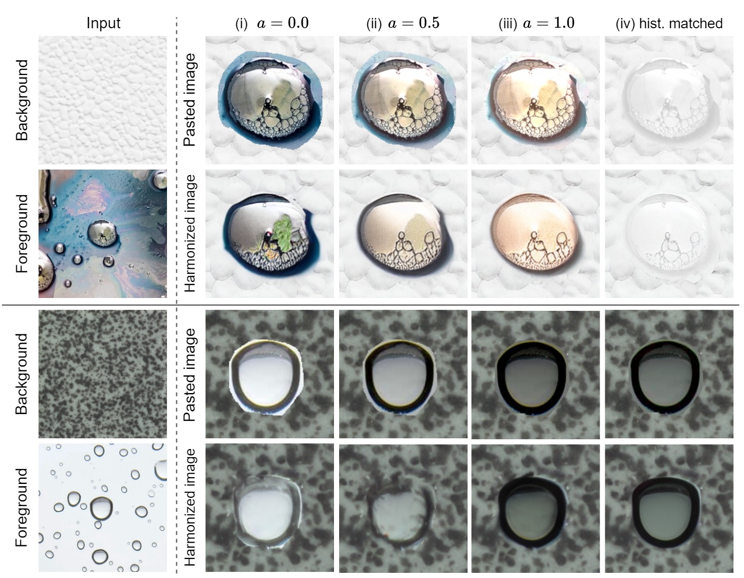
4.6.1 Effectiveness of Color Shift
We assessed our color shift method’s efficacy by varying the parameter in Eq. 1 and comparing it with histogram matching, a method that fully adjusts the source image’s color to match the target. The experiment was conducted under four conditions: (i) no color adjustment (i.e., (1) with ), (ii) color adjustment via the proposed color shift method (1) with , (iii) color adjustment via the proposed color shift method (1) with , and (iv) color adjustment via histogram matching. It should be noted that, except for color adjustment, all other settings were consistent across all three conditions.
The qualitative results under these conditions are shown in Fig. 4. For reference, we also include pasted images, which are geometry images obtained under each condition directly pasted onto the target image. Comparing (i) and (ii), (iii) in Fig. 4, we can see that without color adjustment, the texture remained unchanged, while with color shift, the geometry was reconstructed with a texture that was blended into the target image. Also, comparing (ii), (iii) and (iv), we find that when histogram matching was used, the relative color changes within the source image area to be transplanted were not preserved, resulting in loss of three-dimensionality. Finally, comparing (ii) and (iii), a stronger color shift tends to improve texture blending, but tends to reduce the three-dimensionality of the object, making it difficult to maintain the original geometry. These results suggest that a modest shift in the color of the source image to that of the target image is effective in transferring geometry.
4.6.2 Effectiveness of Texture-aligning Attention
We examined the effectiveness of Texture-aligning Attention. As previously explained, the primary objective of the inversion phase is to align the geometry image, created from the source image, with the visual domain of the target image. Intuitively, one might expect that using only the keys and values computed from the target image in Eq. 3, while eliminating and derived from the geometry image, would yield results more harmoniously integrated with the target image.
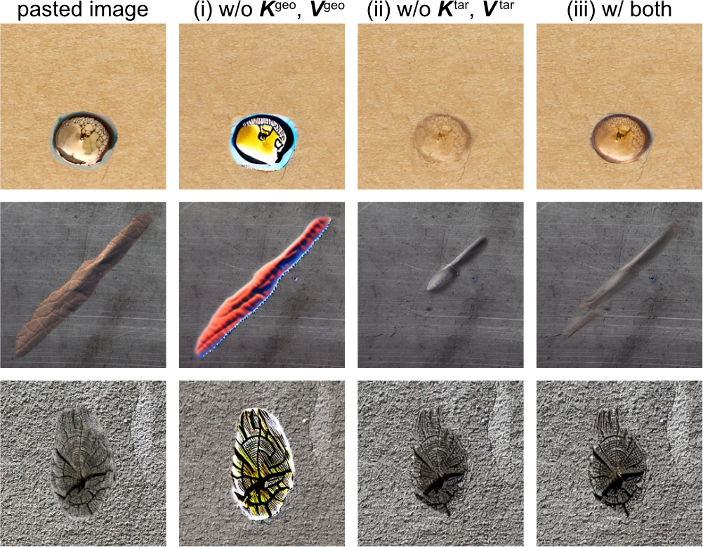
To evaluate the impact of each , on this alignment, we conducted an ablation study comparing three inversion configurations: (i) employing only target-image-derived attention (i.e., eliminating and ), and (ii) utilizing only geometry-image-derived attention (i.e., removing and ). (iii) using both geometry-image-derived and target-image-derived attention components, It is noted that we used the same settings for editing, blending, and generation.
Figure 5 presents a comparative analysis of generation results under the three conditions. Contrary to the initial intuition, the samples for condition (i) demonstrate that using only and does not lead to better integration with the target image. Instead, as shown in condition (iii), using geometry-derived attention components yields results that are more harmoniously blended with the target image. Even when comparing conditions with geometry-derived attention, the presence of target-derived attention tends to accentuate the source geometry. A comparative analysis of columns (ii) and (iii) in Fig. 5 revealed notable distinctions. In the first row, the absence of target-derived attention in column (ii) results in the disappearance of geometry. Conversely, in the second row, column (ii) exhibits partial omission of geometry. These observations suggest the effectiveness of employing both geometry-derived and target-derived attention in geometry transfer.
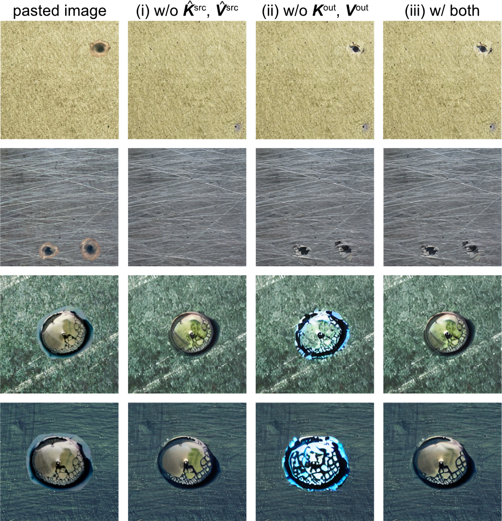
4.6.3 Effectiveness of Geometry-preserving Attention
We investigated the significance of Geometry-preserving Attention. Specifically, we compared generation results under three conditions: (i) employing only self-attention (i.e., eliminating and ), and (ii) utilizing only source-image-derived attention (i.e., removing and ). (iii) using both self-attention and source-image-derived attention components (i.e., using Geometry-preserving Attention as defined in Eq. 5). Figure 6 provides a qualitative analysis of the generation results. Comparing (i) and (ii) or (iii), it was shown that the absence of source image attention leads to a significant degradation in geometry preservation, particularly evident in the transplantation of smaller regions. As for the comparison of (ii) and (iii), samples in the third and fourth rows illustrate that only using source-image-derived attention results in overemphasized geometry when transplantation regions become larger. These results indicate that although source-image-derived attention plays a key role in maintaining geometry information, the influence needs to be balanced by using self-attention simultaneously.
4.7 Limitation
The primary limitation of our work lies in its difficulty in transferring extremely large or small geometries. As evident from Eqs. 3 and 5, the ratio of texture-related to geometry-related information in our customized attention calculation is strongly dependent on the size of the geometry transfer area. In addition, the generated output occasionally exhibits significant geometric deviations from intended results or produces unrelated content. This limitation might be attributed to our method’s reliance on a pretrained SD model without additional training, potentially constraining its ability to fully capture texture and geometry. Future improvements could focus on dynamically adjusting attention based on transfer area size, developing more robust attention mechanisms for diverse image combinations, and expanding generatable geometries through advanced training or architectural improvements. These refinements aim to address the current limitations and further improve the versatility and reliability of our approach across a wider range of geometry and image combinations.
5 Conclusion
In this work, we introduce Harmonizing Attention, a novel approach that facilitates the effective capture and transfer of material-independent geometry while preserving material-specific textural continuity. Our method uses custom Texture-aligning and Geometry-preserving Attention during inversion and generation processes, respectively, enabling the simultaneous referencing of source geometry and target texture information. Our approach achieves effective geometry transfer without requiring additional training or prompt engineering. Our method presented herein not only improves the creation of photorealistic composites but also expands the horizons of computer vision applications, ranging from augmented reality to advanced image editing.
References
- [1] D. Cohen-Or, O. Sorkine, R. Gal, T. Leyvand, and Y.-Q. Xu, “Color harmonization,” ACM Transactions on Graphics, vol. 25, no. 3, pp. 624–630, 2006.
- [2] J. Jia, J. Sun, C. Tang, and H. Shum, “Drag-and-drop pasting,” ACM Transactions on Graphics, vol. 25, no. 3, pp. 631–637, 2006.
- [3] J.-F. Lalonde and A. A. Efros, “Using color compatibility for assessing image realism,” in Proceedings of the IEEE International Conference on Computer Vision (ICCV), 2007.
- [4] P. Perez, M. Gangnet, and A. Blake, “Poisson image editing,” ACM Transactions on Graphics, vol. 22, no. 3, pp. 313–318, 2003.
- [5] F. Pitie, A. C. Kokaram, and R. Dahyot, “N-dimensional probability density function transfer and its application to color transfer,” in Proceedings of the IEEE International Conference on Computer Vision (ICCV), 2005.
- [6] E. Reinhard, M. Ashikhmin, B. Gooch, and P. Shirley, “Color transfer between images,” IEEE Computer Graphics and Applications, vol. 21, no. 5, pp. 34–41, 2001.
- [7] K. Sunkavalli, M. K. Johnson, W. Matusik, and H. Pfister, “Multi-scale image harmonization,” ACM Transactions on Graphics, vol. 29, no. 4, pp. 125:1–125:10, 2010.
- [8] M. W. Tao, M. K. Johnson, and S. Paris, “Error-tolerant image compositing,” in Computer Vision – ECCV 2010 (K. Daniilidis, P. Maragos, and N. Paragios, eds.), vol. 6311 of Lecture Notes in Computer Science, (Berlin, Heidelberg), pp. 31–44, Springer, 2010.
- [9] S. Xue, A. Agarwala, J. Dorsey, and H. E. Rushmeier, “Understanding and improving the realism of image composites,” ACM Transactions on Graphics, vol. 31, no. 4, pp. 84:1–84:10, 2012.
- [10] J.-Y. Zhu, P. Krähenbühl, E. Shechtman, and A. A. Efros, “Learning a discriminative model for the perception of realism in composite images,” in Proceedings of the IEEE International Conference on Computer Vision (ICCV), 2015.
- [11] W. Cong, J. Zhang, L. Niu, L. Liu, Z. Ling, W. Li, and L. Zhang, “Dovenet: Deep image harmonization via domain verification,” in Proceedings of the IEEE/CVF Conference on Computer Vision and Pattern Recognition (CVPR), 2020.
- [12] X. Cun and C.-M. Pun, “Improving the harmony of the composite image by spatial-separated attention module,” IEEE Transactions on Image Processing, vol. 29, pp. 4759–4771, 2020.
- [13] Z. Guo, D. Guo, H. Zheng, Z. Gu, B. Zheng, and J. Dong, “Image harmonization with transformer,” in Proceedings of the IEEE/CVF International Conference on Computer Vision (ICCV), pp. 14870–14879, October 2021.
- [14] Y. Jiang, H. Zhang, J. Zhang, Y. Wang, Z. Lin, K. Sunkavalli, S. Chen, S. Amirghodsi, S. Kong, and Z. Wang, “SSH: A self-supervised framework for image harmonization,” in Proceedings of the 2021 IEEE/CVF International Conference on Computer Vision (ICCV), pp. 4812–4821, 2021.
- [15] J. Ling, H. Xue, L. Song, R. Xie, and X. Gu, “Region-aware adaptive instance normalization for image harmonization,” in Proceedings of the IEEE/CVF Conference on Computer Vision and Pattern Recognition (CVPR), pp. 9357–9366, 2021.
- [16] W. Cong, L. Niu, J. Zhang, J. Liang, and L. Zhang, “Bargainnet: Background-guided domain translation for image harmonization,” in Proceedings of the 2021 IEEE International Conference on Multimedia and Expo (ICME), pp. 1–6, 2021.
- [17] K. Sofiiuk, P. Popenova, and A. Konushin, “Foreground-aware semantic representations for image harmonization,” in WACV, pp. 1620–1629, 2021.
- [18] Z. Guo, Z. Gu, B. Zheng, J. Dong, and H. Zheng, “Transformer for image harmonization and beyond,” IEEE Transactions on Pattern Analysis and Machine Intelligence, vol. 45, no. 11, pp. 12960–12977, 2022.
- [19] Y. Hang, B. Xia, W. Yang, and Q. Liao, “Scs-co: Self-consistent style contrastive learning for image harmonization,” in 2022 IEEE/CVF Conference on Computer Vision and Pattern Recognition (CVPR), pp. 19678–19687, 2022.
- [20] Y. Song, Z. Zhang, Z. Lin, S. Cohen, B. Price, J. Zhang, S. Y. Kim, and D. Aliaga, “Objectstitch: Object compositing with diffusion model,” in Proceedings of the IEEE/CVF Conference on Computer Vision and Pattern Recognition (CVPR), pp. 18310–18319, June 2023.
- [21] S. Lu, Y. Liu, and A. W.-K. Kong, “TF-ICON: Diffusion-based training-free cross-domain image composition,” in Proceedings of the IEEE/CVF International Conference on Computer Vision (ICCV), pp. 2294–2305, 2023.
- [22] Y.-H. Tsai, X. Shen, Z. Lin, K. Sunkavalli, X. Lu, and M.-H. Yang, “Deep image harmonization,” in Proceedings of the IEEE Conference on Computer Vision and Pattern Recognition, pp. 3789–3797, 2017.
- [23] J.-F. Lalonde and A. A. Efros, “Using color compatibility for assessing image realism,” in Proceedings of the 2007 IEEE 11th International Conference on Computer Vision (ICCV), pp. 1–8, 2007.
- [24] H. Wu, S. Zheng, J. Zhang, and K. Huang, “GP-GAN: Towards realistic high-resolution image blending,” in Proceedings of the 27th ACM International Conference on Multimedia, pp. 2487–2495, 2019.
- [25] L. Tan, J. Li, L. Niu, and L. Zhang, “Deep image harmonization in dual color spaces,” in Proceedings of the 31st ACM International Conference on Multimedia, pp. 2159–2167, 2023.
- [26] H. Chen, Z. Gu, Y. Li, J. Lan, C. Meng, W. Wang, and H. Li, “Hierarchical dynamic image harmonization,” in Proceedings of the 31st ACM International Conference on Multimedia, pp. 1422–1430, 2023.
- [27] Y. Xing, Y. Li, X. Wang, Y. Zhu, and Q. Chen, “Composite photograph harmonization with complete background cues,” in Proceedings of the 30th ACM International Conference on Multimedia, pp. 2296–2304, 2022.
- [28] L. Lu, J. Li, J. Cao, L. Niu, and L. Zhang, “Painterly image harmonization using diffusion model,” in Proceedings of the 31st ACM International Conference on Multimedia, p. 233–241, Association for Computing Machinery, 2023.
- [29] T.-F. Hsiao, B.-K. Ruan, and H.-H. Shuai, “Training-and-prompt-free general painterly harmonization using image-wise attention sharing,” 2024. arXiv:2404.12900v1 [cs.CV].
- [30] R. Rombach, A. Blattmann, D. Lorenz, P. Esser, and B. Ommer, “High-resolution image synthesis with latent diffusion models,” in Proceedings of the IEEE/CVF Conference on Computer Vision and Pattern Recognition (CVPR), pp. 10684–10695, June 2022.
- [31] J. Song, C. Meng, and S. Ermon, “Denoising diffusion implicit models,” in Proceedings of the International Conference on Learning Representation (ICLR), 2021.
- [32] D. Garibi, O. Patashnik, A. Voynov, H. Averbuch-Elor, and D. Cohen-Or, “ReNoise: Real image inversion through iterative noising,” 2024. arXiv:2403.14602v1 [cs.CV].
- [33] P. Bergmann, K. Batzner, M. Fauser, D. Sattlegger, and C. Steger, “The MVTec anomaly detection dataset: A comprehensive real-world dataset for unsupervised anomaly detection,” International Journal of Computer Vision, vol. 129, pp. 1038–1059, April 2021.
- [34] P. Bergmann, M. Fauser, D. Sattlegger, and C. Steger, “MVTec AD—A comprehensive real-world dataset for unsupervised anomaly detection,” in 2019 IEEE/CVF Conference on Computer Vision and Pattern Recognition (CVPR), pp. 9584–9592, 2019.
- [35] R. Zhang, P. Isola, A. A. Efros, E. Shechtman, and O. Wang, “The unreasonable effectiveness of deep features as a perceptual metric,” in Proceedings of the 2018 IEEE/CVF Conference on Computer Vision and Pattern Recognition (CVPR), pp. 586–595, 2018.
- [36] A. Radford, J. W. Kim, C. Hallacy, A. Ramesh, G. Goh, S. Agarwal, G. Sastry, A. Askell, P. Mishkin, J. Clark, G. Krueger, and I. Sutskever, “Learning transferable visual models from natural language supervision,” in Proceedings of the 38th International Conference on Machine Learning (M. Meila and T. Zhang, eds.), vol. 139 of Proceedings of Machine Learning Research, pp. 8748–8763, PMLR, 18–24 Jul 2021.
- [37] K. Ding, K. Ma, S. Wang, and E. P. Simoncelli, “Image quality assessment: Unifying structure and texture similarity,” IEEE Transactions on Pattern Analysis and Machine Intelligence, vol. 44, no. 5, pp. 2567–2581, 2020.
- [38] B. Yang, S. Gu, B. Zhang, T. Zhang, X. Chen, X. Sun, D. Chen, and F. Wen, “Paint by example: exemplar-based image editing with diffusion models,” in Proceedings of the IEEE/CVF Conference on Computer Vision and Pattern Recognition (CVPR), pp. 18381–18391, 2023.