Interference-Free Backscatter Communications for OFDM-Based Symbiotic Radio
††thanks: M. B. Janjua is with the Department of Electrical and Electronics Engineering, Istanbul Medipol University, Istanbul, 34810, Turkey (email: muhammad.janjua@std.medipol.edu.tr). A. Şahin is with the Electrical Engineering Department, University of
South Carolina, Columbia, SC, USA. (email: asahin@mailbox.sc.edu). H. Arslan is with the Department of Electrical and Electronics Engineering, Istanbul Medipol University, Istanbul, 34810, Turkey (email: huseyinarslan@medipol.edu.tr)
††thanks: This paper has been accepted for publication in part to IEEE Global Communication Conference (GLOBECOM) 2024 [1]
Abstract
This study proposes an orthogonal frequency division multiplexing (OFDM) based scheme to achieve interference-free backscatter communications (BC) in a symbiotic radio system. In specific, we propose three frequency shift keying (FSK)-based backscatter modulation schemes to shift the primary signal, i.e., the OFDM symbols transmitted from a base station (BS), in the frequency domain to transmit its information. Symbiotically, the BS empties specific subcarriers within the band so that the received frequency-shifted signals from the backscatter device and the primary signal are always orthogonal. The first scheme relies on the combination of on-off keying (OOK) within the FSK modulation while the second and the third schemes are based on the conventional FSK modulation with different in-band null-subcarrier allocation. These schemes allow the use of non-coherent detection at the receiver which addresses the channel estimation challenge for the signals arriving from a backscatter device. We derive the bit-error rate performance of the detector theoretically. The comprehensive simulations show that the proposed approach achieves a lower bit-error rate up to at dB with BC by eliminating direct link interference.
Index Terms:
Symbiotic radio, backscatter communication, OFDM, FSK, OOK, subcarrier allocation, and interference management.I Introduction
Next-generation wireless networks are expected to be energy-efficient and sustainable by supporting use cases that involve Internet-of-Things (IoT) devices with very low power consumption [2]. In this direction, passive and ambient IoT devices were studied in the fifth-Generation (5G) New Radio Release 18 and Release 19 [3]. The ambient devices can be battery-less or have a battery and operate with the harvested energy from radio waves or other sources [4]. Under such limitations, modulation techniques relying on active components may not be feasible for communication due to their high power consumption, leading to the backscatter communications (BC) paradigm that is widely used in radio frequency identification (RFID) systems for low-power information transfer [5, 6, 7, 8, 9]. With BC, the data is transmitted by modulating the response of the antenna to the incoming radio frequency (RF) signals. In the RFID systems, a dedicated RF signal exciter is deployed to transmit unmodulated carrier signals for BC. As the coverage area and the number of tags (i.e., backscatter device (BD)) increases, more carrier exciters are needed to serve all the BDs in the environment. Considering the limitations of RFID systems, an ambient BC is developed in which a BD utilizes the signals transmitted by existing wireless systems as a carrier for data transmission [10]. The ambient BC eliminates the need for a dedicated device for carrier signal transmission and opens a new era of BC. However, the reliability of ambient BC is very low due to the interference between the unknown strong RF and weak backscatter signal at the intended receiver (RX). In this study, we address this interference challenge with the concept of symbiotic radio (SR) by designing the incoming RF signals.
The idea of SR for BC in passive IoT was first thoroughly investigated in [11], where the BD was considered a parasitic entity in a primary system, e.g., an existing wireless system. In contrast to ambient BC, BD is regarded as a component of the primary system in SR and shares radio resources with the primary user, with the primary transmitter being designed to support its requirements. In [12], the authors show that SR can exploit the benefits of ambient BC and cognitive radio since SR can share share the spectrum between primary users and BD. Also, it can provide highly reliable BC through a joint decoder at the receiver. The authors in [13] and [14] analyze the mutualistic relationship between BD and a primary system in SR, where both systems benefit each other by sharing the radio resource. Some other SR-based relationships between low-power IoT devices and existing wireless systems are explored in [15, 16, 17, 18, 19]. These earlier studies suggest that by cooperative resource sharing and system design, SR can avoid the need for new infrastructure to support BC and may allow the network to overcome the coexistence issues. Also, SR can mitigate interference between the primary and backscatter signals. Since most wireless systems, including cellular and Wi-Fi networks, utilize orthogonal frequency division multiplexing (OFDM) as their standard waveform, an opportunity arises to design the OFDM signal in SR to address the interference issue in BC concerning ambient IoT devices.
Exploiting the OFDM signal for BC is critical for low-power passive IoT devices as they coexist with the existing wireless systems. Within this context, multiple studies consider OFDM-based BC [20, 21, 22, 23, 24, 25, 26]. These studies explore the cyclostationary features of OFDM signal generated by an ambient wireless system for BC. In [20], a backscatter modulation scheme is designed for BC over OFDM signal in the time domain. The uncorrupted part of the cyclic prefix (CP) is processed at the receiver for direct link interference cancellation and BD signal detection. Still, the receiver must know the channel’s lengths for this scheme to work in practical scenarios. Also, the waveform designed for BC causes variation in the primary signal, which may lead to interference at the primary receiver. The guard bands in the OFDM signal are used for BC in [22, 21, 27]. Specifically, a BD applies frequency-shift keying (FSK) to shift the spectrum of the backscatter signal to the out-of-band region of the primary OFDM signal to transmit its information. This approach cannot be directly implemented in SR as the joint receiver needs to scan the adjacent channel to detect the data of BD, which requires an additional filter to capture the backscatter signal in the guard subcarriers. Consequently, this solution adds complexity to the receiver. The authors in [23] introduce the subcarrier-wise ambient BC and propose to transmit one-bit information at each subcarrier. This scheme requires a bank of passive notch filters at the BD, significantly increasing its hardware complexity. The preamble and pilots in OFDM signals are used for ambient BC in [24, 25, 26, 28], but utilizing the preamble and pilots degrades the channel estimation performance at the primary receiver, which reduces the reliability of the whole system. Additionally, this approach requires strict synchronization at the backscatter receiver. Besides, in [28], the authors propose to use the cell-specific reference signals in the long-term evolution (LTE) system to enable BC. In particular, the BD applies FSK to create an artificial Doppler in the incident LTE signal and shift the reference signals to another subcarrier to transmit its information. To this end, the BD and backscatter receiver must have prior information on LTE reference signals. Nevertheless, these studies do not mainly design the OFDM symbols to achieve reliable BC for an SR system. For instance, it is possible to arrange the data, pilot, and null subcarriers at the primary system to receive the direct path and BC signals over different subcarriers if BD is capable of manipulating the signal frequency [29]. This arrangement can be achieved without changing the transceiver design of the primary system. Furthermore, such a system can support passive IoT devices and ambient power-enabled IoT devices in various wireless networks, including Wi-Fi, LTE, 5G, and beyond.
I-A Contributions
In this work, we propose an OFDM-based scheme in the context of SR. Our contributions can be listed as follows:
-
•
We design the OFDM signal transmitted from a base station (BS) such that it is always orthogonal to the backscatter signal within the band. To this end, we utilize FSK modulations at the BD and shift the data symbols to the subcarriers dedicated to BD in the frequency domain. As a result, the primary user’s and BD’s data are received on separate subcarriers within the received OFDM signal, and the interference originating from the direct link is circumvented.
-
•
By extending our preliminary work in [1], we analyze and compare the on-off keying (OOK) modulation with FSK modulation schemes for BC. The proposed OOK waveform shifts the data symbols to the subcarriers dedicated to BD during on period. We provide the theoretical derivation for the error rate based on Lemma 1. We evaluate the retransmission probability of the proposed schemes based on the RFID Gen2 standard -bit cyclic redundancy check (CRC) encoder/decoder.
-
•
We show the efficacy of the non-coherent detector in receiving BD’s data at RX. We analyze the error-rate performance of the non-coherent detector analytically and assess the scheme via comprehensive simulations. We also demonstrate the impact of hardware impairments, specifically carrier frequency offset (CFO), on the efficiency of FSK-based BC schemes.
Organization: The rest of the paper is organized as follows. Section II elaborates on the SR system design and the notations and preliminaries used in the rest of the sections. Section III discusses the proposed schemes in detail. In Section IV, non-coherent detection and performance analysis are presented. Section V provides the simulation and theoretical results and detailed discussions. The concluding remarks are given in Section VI.
Notation: The sets of complex numbers and positive integers are denoted by and , respectively. represents the expectation of its argument over random variables. is the circularly symmetric complex Gaussian distribution with zero mean and variance. denotes the cardinality of a set . represents the probability of an event given the event . represents the probability of an event . represents the floor function. is the circular convolution operation, and represents the linear convolution.
II Symbiotic Radio System Model
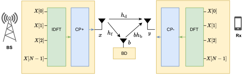
Consider an OFDM-based SR system consisting of two primary devices, i.e., a BS, an RX, and a BD, as shown in Figure 1, where BS and RX are assumed to be single-antenna active devices, and BD is a single-antenna passive device. The BD is a low-power, low-cost, and low-complexity device that belongs to a passive IoT system. The primary signal transmitted by BS is utilized as BD’s carrier signal to transmit its information using BC to the RX. Furthermore, the primary signal is a modulated signal containing the information for the RX, and the RX’s goal is to obtain the information that is transmitted from both BD and BS.
II-A Primary Signal
The primary signal is an OFDM symbol with active subcarriers containing data symbols for RX. Let be the -th data symbol at BS. After an inverse discrete Fourier transform (IDFT) is applied to the data symbols, the -th time domain sample of the corresponding OFDM symbol, denoted by , can be expressed as
| (1) |
where is the IDFT size. Afterward, a CP of length that is larger than the maximum delay spread is added to the time domain signal and the corresponding OFDM samples are transmitted over a wireless channel. The bandpass signal transmitted by the BS can be written as
| (2) |
where is the baseband OFDM signal with CP in the time domain, and denotes the carrier frequency.
II-B BD Signal
Conventionally, the load modulation is applied by switching the BD’s antenna between non-reflecting and reflecting states for transmit and , respectively [5]. The achievement of the reflecting state involves impedance matching, which is realized by connecting an antenna with an impedance of to a load with an impedance of , ensuring . As the matches with the , maximum power transfers from the source (i.e., antenna) to the load, which is used to energy harvesting or detect the information in the signal. Conversely, impedance mismatching is implemented to obtain a non-reflecting state by connecting the antenna to the load in such a way that . Based on the mismatch between the and , power is reflected from the source, which is used to backscatter the incident signal. It is noted that the amount of power transfer between the source and the load is related to the impedance matching and mismatch such that the perfect matching leads to maximum power transfer from the load to source, whereas the perfect mismatch results in minimal power transfer to the load and maximum power reflection from the source. Hence, the reflection coefficient for a backscatter modulator is expressed as [30]:
| (3) |
Different values of can be obtained by changing the values of because the value of is constant based on the antenna structure. The amplitude and phase of the backscatter signal are described by and phase , which can be defined as [31]:
| (4) |
| (5) |
The impedance of the BD can be manipulated to attain complex values by carefully selecting appropriate inductance values. By connecting an RF switch to the loads and alternately switching between them, the BD can effectively replicate the complex signal with a frequency of [32, 33]. Here, represents the frequency index for shifting the primary signal’s data symbols. By precisely controlling the amplitude and frequency of the reflected signal, both OOK and FSK modulations can be generated to transmit the information from the BD.
Conventionally, a BD modulates the incoming signal with a rectangular pulse generated by switching between two loads [5]. Such a modulation technique is not preferable for a receiver in SR as changing load sharply requires BD to transmit in the out-of-band region of the primary communication system. One of the methods to tackle this concern is pulse-shaping, which involves continuous load variations at BD for BC [34]. A BD consists of a variable load (i.e., diode) controlled by a microcontroller unit (MCU). The MCU applies different voltage levels to the diode to perform continuous load modulations. This approach suppresses the out-of-band emissions and allows the synthesis of specific signals like a complex exponential for frequency modulation or shapes the time-frequency characteristics of the reflected signal. Besides, other BD hardware architectures and designs are available in the literature that can generate complex signals to achieve single side-band FSK without higher order and mirror harmonics [32]. As BD design is not part of this study, interested readers are directed to the works in [35] and [36].
In this study, we consider a BD consisting of multiple loads (i.e., diode or transistors) and an MCU discussed in [32, 37, 35], which can perform single side-band FSK and OOK modulations. We assume that the BD’s MCU and other low-power operations are supported by harvesting ambient sources like RF signals or solar energy [11]. Let BD use frequency modulation to transmit information. Then, the frequency-modulated primary signal at the output of BD can be written as
| (6) |
where is the signal generated at the BD, and represents the channel on the forward link (i.e., the link between BS and BD). Note that the implementations of single side-band FSK discussed in [32] and [37] can be used to obtain in practice. The rationale for employing FSK modulation is to enable the orthogonal reception of the primary signal and the BD signal at the receiver. Alternative modulation schemes, such as phase shift keying (PSK) and Minimum shift keying (MSK), could potentially be used for the BD signal. However, these other modulation approaches would come at the cost of performance degradation, loss of orthogonality between the primary and BD signals, and increased receiver complexity.
II-C Received Signal
The signal transmitted by the BS is received at the RX from the direct link and the backscatter link. The superposed signal in the baseband can be expressed as
| (7) |
where is the RX data signal, is the BD data signal, denotes the convolution operation, and is the additive white Gaussian noise. The functions and represent the continuous-time channel for the direct link (between BS and RX) and backward link (between BD and RX), respectively. Each channel path follows the multi-path Rayleigh fading, i.e., with complex amplitude and delay of the th path. The maximum delay excess delay of the composite channel is , where , , and represent the time delay corresponding to direct, forward, and backward links. After the CP is discarded, the received signal at the RX in the discrete-time can be written as
| (8) |
where is the signal received from the BS through the direct link, is the signal received from the BD over the backscatter link, , , , , and represent the direct channel, forward channel, backward channel, primary signal, and backscatter signal in the discrete-time domain, respectively, and is the additive white Gaussian noise with zero mean and variance.
We note from (8) that if OOK modulation is used at BD and the RX receives the superposed and signals over the same frequency band, i.e., the signal interferes with the signal due to high channel gains. Then, the RX must decode the primary signal and perform successive interference cancellation before detecting the BD information from . The primary signal decoding is not feasible in ambient BC systems as the primary data is unknown to the RX. In an SR system, such a decoding process degrades the performance of the BD detector significantly and negatively impacts the reliability of the BC. Moreover, successive interference cancellation increases the complexity of the RX. On the other hand, in FSK-based approaches used in ambient BC [21], an unutilized frequency band other than the band of the primary signal is required to shift the primary signal and avoid direct link interference. To achieve a reliable BC in an OFDM-based SR system, we propose a scheme to prevent direct link interference at the RX, which will be discussed in the next section.
III Proposed Schemes for Interference-Free BC
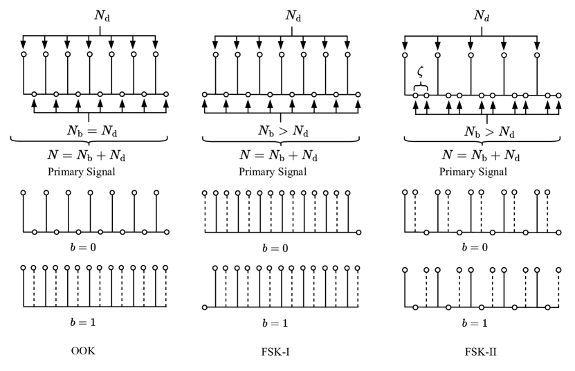
The conventional 5G and Wi-Fi systems use OFDM as the standard waveform [38, 39], in which data symbols are placed in the frequency domain over the narrow band subcarriers. In the OFDM-based SR, BD modulates the incoming signal by changing its amplitude, phase, or frequency shift. In the case of amplitude and phase modulation BD, RX receives the primary signal with modified amplitude or phase, but data symbols in the primary signal coming from backscatter and direct path interfere. However, one way to avoid this interference is to shift the data in the primary signal in the frequency with FSK at the BD. For instance, if subcarriers exist in the OFDM symbol, BD can shift the primary data to those subcarriers to prevent the backscatter signal from the direct path signal interference and vice versa. By exploiting this approach, we propose the placement of null subcarriers within the OFDM symbol for interference-free BC. Let and denote the number of subcarriers for BD and RX, respectively. To receive the BD information with OOK, must be equal to ; however, must be greater than to receive the BD information with FSK.
III-A Proposed Scheme for OOK Modulation
OOK is an amplitude-shift keying (ASK) modulation in which the information is represented with two amplitudes, i.e., ON and OFF. In terms of BC, OOK is performed by switching the antenna between reflecting and non-reflecting states to cause a change in the backscatter signal [40]. In the proposed system, BD also switches reflecting states at a different rate to cause a frequency shift in the backscatter signal while transmitting information bit . The BD waveform can be expressed as
| (9) |
where with representing the subcarrier spacing in the OFDM signal. Unlike the conventional OOK modulation, the BD shifts the data in the primary signal to transmit bit and remain constant for bit . The RX detects the BD’s information from the null subcarriers.
In the proposed approach for OOK-based BC without interference, null subcarriers are placed between adjacent data subcarriers, as illustrated in Figure 2. The subcarrier allocation for primary data and BC at the BS can be expressed as
| (10) |
where with , and with denotes the primary data symbol. In the OOK scheme, the BD shifts the data in the incoming signal with frequency with to transmit bit over the null subcarrier. The RX receives the BD bits and primary data symbols over null subcarriers and data subcarriers, respectively, as illustrated in Figure 2. Thus, the OOK scheme prevents interference from the primary signal to the BD signal at RX. Here, we mentioned only single data and corresponding null subcarrier placement. However, different arrangements can be made to allocate more than one data subcarrier together. For instance, two data subcarriers followed by two null subcarriers can also be placed to achieve the BC without interference at the RX. In that case, a general subcarrier allocation at the BS for OOK modulation can be expressed as
| (11) |
where and subcarrier index . Now, to prevent direct link interference when two data subcarriers are placed next to each other, the BD shifts the signal with frequency to transmit bit .
III-B Proposed Schemes for FSK Modulation
In this study, we consider two FSK strategies discussed in the following subsections.
III-B1 FSK-1: Dual-Side Single-Null Subcarrier-Based FSK
Let one BD bit duration span one OFDM symbol duration, then the backscatter modulation in FSK-1 approach can be expressed as
| (12) |
To enable interference-free BC with FSK-1 approach, the null subcarriers are allocated between the data subcarriers such that a null subcarrier is placed before the data subcarrier so the BD can shift the signal to different frequencies and the RX can detect both the direct link and backscatter signal information at different subcarriers allocated to each of them. According to FSK-1, the data symbols are mapped to the subcarriers as
| (13) |
where with . Thus, one subcarrier adjacent to each data subcarrier is left as a null subcarrier.
Upon receiving the OFDM signal with this subcarrier allocation, BD shifts the signal as follows: If the transmit information bit is , BD shifts the data subcarriers to the previous null subcarrier. If it transmits , BD shifts the data subcarriers to the next null subcarriers, as shown in Figure 2. The FSK-1 approach is applicable only for the binary FSK modulation because more null subcarriers are needed between the data subcarriers to enable a higher-order FSK without direct link interference. For instance, if the BD shifts the incident signal with a frequency equal to two subcarriers, the first data subcarrier interferes with the subsequent data subcarrier.
III-B2 FSK-2: Single-Side Multi-Null Subcarrier-Based FSK
To improve the reliability of FSK-based BC, we introduce FSK-2 that can use multiple null subcarriers, as shown in Figure 2. With FSK-2, the data symbols are mapped to the subcarriers as
| (14) |
where is the number of null subcarriers between two adjacent data subcarriers and for . For binary FSK, two null subcarriers are allocated between two adjacent data subcarriers (i.e., ), and the BD modulates the incident signal by shifting the data symbols to the subsequent subcarriers. For instance, to transmit the information bit , the data symbol is shifted by one subcarrier spacing. On the other hand, the data symbol is shifted by the twice subcarrier spacing to transmit information bit , as shown in Figure 2. Moreover, the value of can be adjusted to achieve a higher order FSK modulation and multiple BD access. The backscatter modulation in FSK-2 approach can be expressed as
| (15) |
It is worth noting that FSK-1 is spectrally efficient compared to FSK-2. However, it is less reliable if the detector at the RX relies on the single-null subcarrier at the band’s edges. FSK-2 utilizes a larger number of null subcarriers than FSK-1. The inclusion of these additional null subcarriers significantly enhances the reliability of BC in the FSK-2 scheme, as shown in Section V.
IV Non-Coherent Detection and Performance Analysis
The RX receives the signal expressed in (8). After removing the CP and taking the -point discrete Fourier transform (DFT), the received signal can be written as
| (16) | ||||
where denotes the received symbol on the -th subcarrier with , , , and representing , , , and in the frequency domain, respectively. is the Fourier transform of . Since the data from the BD and BS are received at the different subcarriers, we can write the received signal from BS and BD separately as
| (17) |
and
| (18) |
where and represent the index of subcarriers containing data of the BS and BD, respectively. According to the the BD’s modulation, we can express as
| (19) |
IV-A Non-coherent Detector for OOK
In the case of binary transmission from the BD with OOK modulation, can be expressed as
| (20) |
where the . For a large value of , the OFDM signal backscatter by BD with OOK is a sequence of random variables and follows the circularly-symmetric complex Gaussian distribution with zero mean and variance . Without the loss of generality, we assume here that . , and represent the total number of null subcarriers and data subcarriers in an OFDM symbol transmitted by the BS, respectively. After receiving the signal from BS and BD, the RX must detect these signals to retrieve the information. A non-coherent detector is used at RX to detect the signal of BD while considering that the data of the RX is detected in a conventional manner using a coherent detector because both devices’ data are received over the orthogonal subcarriers. Since the non-coherent detector does not require phase information, it can be used in different types of SR systems, like a mutualistic SR system in which BS and BD have a common RX or an ambient SR system where they have separate RXs (i.e., user equipment and ambient RX). Comparatively, in coherent detection, RX must know , , and , which is suitable for an SR with a common RX but not for an SR with an ambient RX [12].
To detect the OOK signal, RX only needs to know the placement of the data and null-subcarriers in the transmitted OFDM signal without , , , and . The information in transmitted by shifting or not shifting the from to can be acquired by detecting the energy at subcarriers. Let be the hypothesis for the likelihood of detecting the signal (i.e., ) at the receiver when no signal was transmitted (i.e., ). This situation occurs when the received signal energy exceeds a predefined threshold. On the other hand, let be the hypothesis for the likelihood of detecting no signal, i.e., when the signal was transmitted, i.e., . This situation occurs when the received signal energy is below a threshold. To test these two hypotheses, we define a test statistic based on
| (21) |
We can also write the according to the information transmitted by BD as
| (22) |
Under when BD transmits bit , the subcarriers allocated for BC only contain noise, and is the sum of the square of the Gaussian random variables. We need to find the distribution of by considering that the square of the sum of two Gaussian random variables (i.e., the real and imaginary part of the noise signal) follows the exponential distribution. However, to find the distribution of the sum of exponential random variables, we need to perform convolution operation equivalent to taking integrals, which is a highly complex undertaking. As is a circularly symmetric complex Gaussian random variable, the characteristic function of is , i.e., the Fourier transform of its probability density function (PDF). For the given , we can find the characteristic function as
| (23) |
where . Then, the PDF of is obtained from characteristic function as
| (24) |
On the other hand, under , the distribution of becomes complicated because of the dependence on the cascaded channels and . For a given , the PDF of the cascaded backscatter channel is derived in Lemma 1.
Lemma 1.
Let have a single path and have a constant value during one OFDM symbol due to the short distance between BD and RX. Then, considering the PDF of becomes
| (25) |
where is the characteristic function, and .
Error Performance
In the present system design, we measure the performance in terms of the probability of error for the non-coherent detector, which is obtained by summing the probability of false alarm (PFA) and probability of miss detection (PMD). The probability of error for given PFA and PMD is expressed as
| (26) |
We can find the and for a given threshold value as
| (27) | ||||
and,
| (28) | ||||
where is the cumulative distribution function (CDF) of , which can be calculated from (24) according to the inversion formula given in [41]:
| (29) |
The decision threshold should be chosen such that it minimizes as
| (30) |
If we consider a fixed and try to minimize , we can find that minimizes . After fixing , we search for a given by using a one-dimensional linear search to find the optimal threshold [21]. Then, we use to calculate the minimum .
Now, we can find the CDF for as a Rayleigh random variable, which is written as
| (31) | ||||
where . is the joint CDF of and , which is obtained from the joint probability distribution of the forward and backward links that follow the Rayleigh distribution. We aim to compute in (28) for BC based on a given . In case the BD is close to the RX, the backward link is a single line-of-sight path, is taken as constant, and (29) can be used to calculate . Otherwise, we marginalize by integrating over to find . Finally, we calculate the using (28) and (27) for a given . As there is no closed-form solution of , we can compute the integrals using any software [42].
IV-B Non-Coherent Detector for FSK
Let , and represent the set of null subcarriers dedicated for BD bit and bit , respectively. The RX then calculates metrics for information bits and as
and,
Finally, it detects the BD’s information by comparing the values of and as
| (32) |
where is the detected BD information. In particular, when is greater than , the detected information is because the BD shifts the primary signal to subcarrier set . However, when the BD shifts the primary signal to , is less than and the RX decides the detected bit as . The detection of the transmitted bit at the RX may be incorrect because the received signal is affected by both the channel conditions and the presence of noise. For instance, if BD transmits the bit , but the value of at the RX is less than , the detected bit is decided to be and vice versa.
The bit-error-rate (BER) of the non-coherent detector can be expressed as
| (33) |
where represents the PMD and denotes PFA. We can express these probabilities as
| (34) |
Finding the distributions of and become complicated because of the dependence on the cascaded channels and . For a given , the PDF of the cascaded backscatter channel can be found according to Lemma 1. Moreover, denotes CDF of , which is obtained as follows:
Theorem 1.
The CDF of can be calculated as:
| (35) |
where
| (36) |
where is the backscatter channel gain with . The characteristic functions , and are given by
| (37) |
and,
| (38) |
respectively, for .
The calculations of (35) and (36) are valid for the cascaded backscatter channel with forward and backward links following the Rayleigh distributions. We marginalize (36) over to find , and compute in (33). Although in (35) is not a closed-form expression, it is an analytical solution that can be evaluated via numerical integration, and can be calculated using (33) accordingly [43].
IV-C Compatibility and Integration
The proposed OFDM-based Symbiotic Radio scheme can be seamlessly integrated with existing communication infrastructure, as the primary signal design is based on established wireless standards such as Wi-Fi, LTE, and 5G, enabling direct compatibility and coexistence [38, 44]. Additionally, the proposed OFDM-based SR scheme can be extended to support multiple BDs using frequency-domain multiplexing. Moreover, the hardware design considerations for the BD are discussed in Section II-B, where it is noted that conventional BDs employ rectangular pulse modulation, which can lead to undesirable out-of-band emissions. To mitigate this issue, continuous load modulation controlled by a microcontroller can be used to facilitate the synthesis of complex signals for frequency modulation [34]. Furthermore, alternative BD architectures have been proposed that can generate single-sideband FSK signals without higher-order harmonics [35, 36]. For the modulation over the primary signal, both the BD and the RX must have prior knowledge of the BS transmission and be synchronized accordingly. As the Rx is a conventional user in our case, it can get the necessary information about the primary signal and can synchronize with the BS using control signals such as primary synchronization signal (PSS) and secondary synchronization signal (SSS) in LTE and 5G standards. However, the BD may require additional control signaling from the BS and dedicated synchronization mechanisms, such as the example discussed in [45], where the BD utilizes the periodicity of LTE signals for synchronization.
V Numerical Results
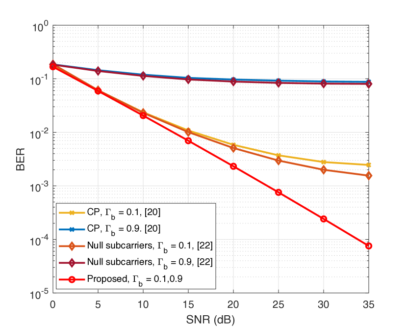
In this section, we evaluate the proposed scheme numerically. We first study the performance of the primary user in OFDM-based SR in the presence of BC and compare it with the techniques in [20, 22]. The baseline scheme in [22] utilizes the guard subcarriers for the BC, which are left in the OFDM symbol in the LTE standard for interference mitigation. Furthermore, the number of guard subcarriers is selected according to the channel bandwidth and subcarrier spacing. For instance, subcarriers are left in the LTE with a MHz bandwidth [46]. Since the primary signals in [20] and [22] are not designed symbiotically, they cause interference to data subcarriers, resulting in increasing BER for the primary communication. We consider a primary system with binary phase shift keying (BPSK) modulation for , and . The information at the BD is modulated with binary FSK modulation. We consider various reflection coefficients with , and the value of is selected according to (30) assuming .
In Figure 3, we analyze the BER performance of different schemes for and . The BER of both CP-based and null-subcarriers-based approaches in [20] and [22] increases as the value of increases. For instance, the BER of these schemes increases from to at a signal-to-noise-ratio (SNR) of dB due to the interference from BC. However, for , the BD reflects the majority of the received power, and the BER for the primary communication in earlier schemes increases drastically. Comparatively, the proposed approaches for OFDM-based SR prevents the interference from BC to primary communication by strategically placing null subcarriers between data subcarriers.
V-A Simulation Results for OOK Scheme
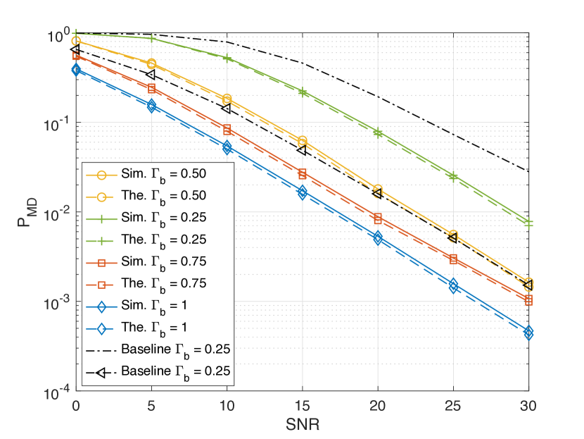
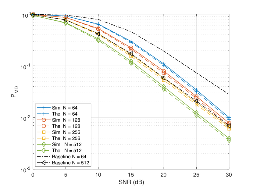
In Figure 4, we analyze the PMD for non-coherent detection of OOK modulated BC signals with , , PFA , , and . As can be seen from Figure 4, the PMD decreases with increasing SNR for a specific value of due to the decrease in the noise power. Furthermore, the increase in the results in low PMD, and the minimum PMD is achieved when because the BD reflects the incident signal with the same input power without loss. Specifically, as the BD’s reflected power increases from to , the PMD decreases from to more than at dB SNR. We compare the performance of the proposed scheme with the baseline BC in [22]. The proposed scheme achieves the same as that of the baseline BC at and dB SNR but with a lower reflection coefficient of . Also, the theoretical PMD results are aligned with the simulation results. The difference is due to the channel correlation.
In Figure 5, we analyze the PMD for non-coherent detection of OOK-modulated BC signals with , , PFA , and . From Figure 5, it is obvious that the PMD depends on the total number of null subcarriers such that as the value of increases from to , PMD reduces to at dB SNR. Compared to the baseline BC scheme in [22], OOK achieves significantly lower for different values of . For instance, the OOK scheme achieves much higher than for while the baseline’s is lower than at dB SNR. The simulation results match the theoretical results; however, there is a difference due to channel correlation. Thus, one way to decrease the PMD of the OOK-modulated BC system is to increase , which is only possible if the OFDM symbol with a large is transmitted.
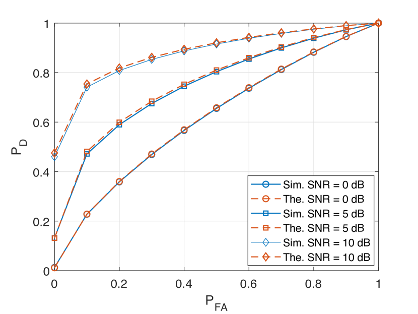
In Figure 6, we analyze the receiver operating characteristic (ROC) of the OOK modulated BC system with , , and for SNR dB. The ROC curve in Figure 6 shows that at dB and PFA, around of the probability of detection (PD) is achieved. As SNR increases with dB, PD increases up to with the same value of PFA. Furthermore, when the SNR is increased by dB more, the PD increases up to at PFA. Besides, ROC curves obtained through simulations are aligned with the theoretical ROC curves for the proposed system with subcarrier allocation for OOK modulated BC. Thus, the system achieves a higher detection accuracy with the non-coherent detector for OOK.
V-B Simulation Results for FSK Schemes
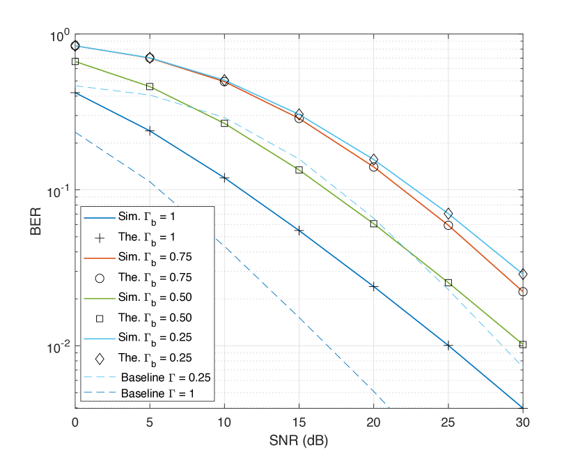
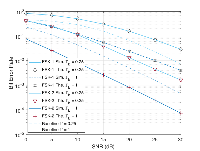
In Figure 7, we consider FSK-1 with , , and . Out of , only two null subcarriers are used to detect the signal according to the subcarrier allocation for FSK-1 modulation. The selection of two specific null subcarriers for non-coherent detection is motivated by the fact that the remaining null subcarriers, except for the first and last subcarriers, typically exhibit equal power at the RX for the transmission of both bit and bit . Hence, the RX can obtain the transmitted bits based on the power discrepancies observed at the RX. The FSK-1 approach enables the non-coherent detector to receive the transmitted data reliably in the presence of the null subcarriers. The system performance is analyzed in terms of BER versus SNR for different values of . It can be seen from Figure 7 that the minimum BER is higher than at SNR dB and but with increasing the value to , BER reduces to . However, as the value of the is increased further to (i.e., a maximum reflection of power at BD), the BER goes below . The simulation results are also perfectly aligned with the theoretical curves for the proposed non-coherent detection method. We compare the performance of the proposed scheme with the baseline BC scheme presented in [21], which utilizes the guard subcarriers to transmit the data of the backscatter device (BD). The baseline scheme outperforms the FSK-1 approach when multiple guard subcarriers are used for BC. If only one guard subcarrier is used, FSK-1 achieves performance similar to the baseline scheme. However, the performance gains of FSK-1 are primarily derived from the primary communication in the SR. In contrast, the primary communication performance degrades significantly in the baseline scheme due to interference between adjacent data subcarriers when FSK-based BC is employed.
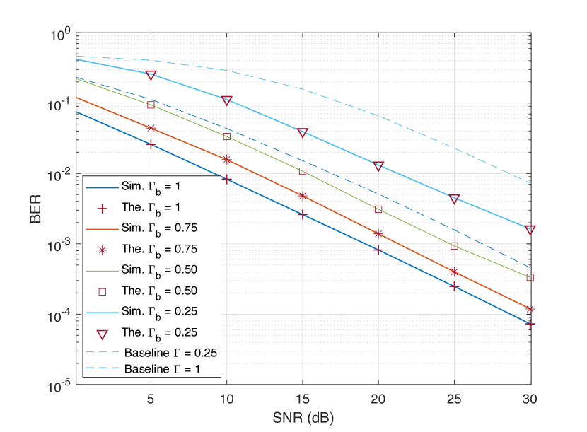
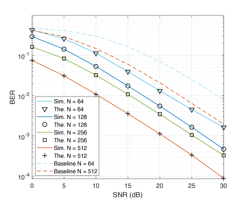
In Figure 8, we present the results of non-coherent detection for the proposed FSK-2 scheme in terms of BER versus SNR with , , and . We assume that is and null subcarriers are used to detect the one information bit transmitted by the BD. The BER performance is analyzed for different values of . Selecting the higher value of results in low BER due to an increase in the backscatter signal power. For instance, when SNR is dB, the BER decreases notably from to by increasing from to . Furthermore, the BER performance of FSK-2 is better than that of FSK-1 and the baseline scheme [21], as shown in Figure 7 and Figure 8. FSK-2 achieves nearly better than the baseline scheme at and for SNR is dB. The BER of FSK-2 is times less than FSK-1 for dB SNR and . The theoretical results also match the simulation results.
In Figure 9, we evaluate the BER performance of FSK-2 for different values of and compare it with the baseline approach [21]. As increases, also increases, which results in a lower BER. For instance, for dB SNR, the BER decreases from to when increases from to . Therefore, one way to improve the performance of the SR with a non-coherent detector for FSK-2 BC is to increase without changing . Furthermore, FSK-2 achieves significantly better performance than that of the baseline scheme. For example, at dB SNR value, FSK-2 achieves close to where the baseline approach’s BER is close to for .
In Figure 10, we analyze the performance of FSK-1 and FSK-2 and compare them with the baseline approach in [21] for different values of . Similar to [22], the baseline approach uses the guard subcarrier instead of dedicated null subcarriers in the OFDM for BC. FSK-2 outperforms the baseline for different values of because the value of is greater than the in-band guard subcarriers in an LTE OFDM, which can be used for BC. For example, the BER of FSK-2 at is higher than the BER of the baseline approach at , which means that the FSK-2 can achieve better with reflection of incident power compared to overcome the performance achieved by the baseline with maximum power reflection. Comparatively, FSK-1’s performance is poor due to the fixed number of null subcarriers for BC (i.e., ).
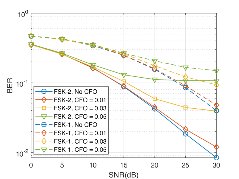
In Figure 11, we analyze the BER performance of the non-coherent detector for different CFO values. Since FSK-1 and FSK-2 schemes shift the incoming signal with a frequency equal to or multiple of the subcarrier spacing (e.g., kHz in LTE and kHz in Wi-Fi). A CFO can introduce an extra frequency shift in the primary signal, leading to inter-carrier interference and degrading the quality of the received signal. Hence, the interference between subcarriers causes poor signal detection of primary and BD signals at RX. For example, a CFO with a value of results in a times increase in the BER of FSK-2 at dB. The performance of FSK-1 also degrades due to CFO but is comparatively less than that of FSK-2. The reduced performance of the FSK-2 scheme compared to FSK-1 can be attributed to the difference in their subcarrier utilization for backscatter communication detection. In the FSK-1 scheme, only the edge subcarriers are used for BD’s data detection, whereas the FSK-2 scheme utilizes all the subcarriers dedicated to BC. When CFO occurs, the data symbols of the primary communication signal shift and encroach onto the null subcarriers, causing interference. This interference affects the performance of both FSK-1 and FSK-2 schemes. However, the impact is more pronounced in the FSK-2 scheme due to the utilization of all the subcarriers dedicated to BC. As the CFO increases, the interference from the primary communication data symbols to the null subcarriers becomes more severe. This increased interference has a more detrimental effect on the FSK-2 scheme, as all the subcarriers used for backscatter communication are affected. In contrast, the FSK-1 scheme, relying only on the edge subcarriers, is relatively less susceptible to this interference, leading to better performance compared to the FSK-2 scheme under large CFO conditions.
V-C Retransmission Probability
In this section, we evaluate the retransmission probability (i.e., the ratio of the retransmitted frames to the total number of transmitted frames) for the non-coherent detector for the proposed schemes based on CRC. We assume a -bit CRC encoder/decoder according to the RFID Gen2 standard [5]. The CRC bits are generated using the polynomial . BD append CRC bit to the information bits before transmission. The RX receives the backscatter signal and applies the CRC decoder after CP removal, IDFT, demodulation, and non-coherent detection processes. If the CRC fails, the RX requests the retransmissions of the data frame through the automatic repeat requests (ARQ) protocol.
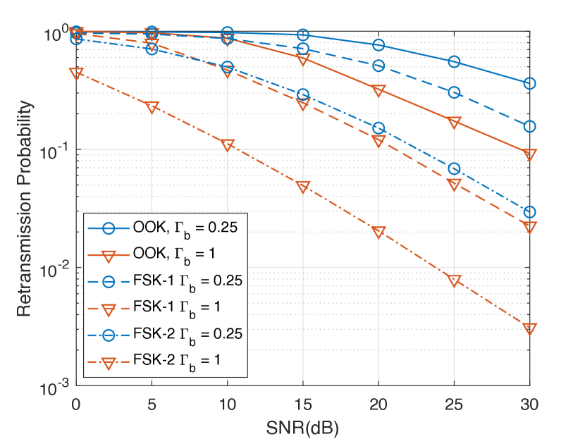
In Figure 12, we present the retransmission probability versus SNR for the proposed OOK, FSK-1, and FSK-2 schemes with non-coherent detection. The frame length is BD bits including CRC bits. The performance is evaluated for . It can be seen from Figure 12 that the FSK-1 provides a lower retransmission probability than OOK at SNR greater than dB. However, FSK-2 outperforms both OOK and FSK-1 by achieving the lowest retransmission probability at different values of . Therefore, to achieve a smaller number of retransmissions in SR for BC, the FSK-2 scheme is preferred even at low with fixed .
V-D Computational Complexity
To analyze the computational complexity of the proposed schemes, we need to consider both the primary signal design and information modulation at the BD. At the BS, the primary signal design involves allocating subcarriers to the RX and BD within an OFDM symbol. This aspect of the design has a computational complexity comparable to conventional OFDM systems used in LTE and 5G standards, which is . The computational complexity of the conventional OFDM and our proposed transmitter’s complexity comes from fast Fourier transform (FFT) operations, which is [38].
When evaluating the complexity associated with different modulation schemes at the BD, it is important to consider how each scheme affects the operations required for information transmission. For conventional OOK, the BD only needs to shift the signal when transmitting a bit ’1’; thus, the complexity is minimal. In contrast, for conventional FSK, the BD must perform frequency shifts for both bits ’1’ and ’0’, which increases complexity. The computational complexity of the BD, therefore, depends on the proposed modulation scheme used. For the proposed FSK-1 and FSK-2 schemes, which involve levels of impedance switching, the complexity is . For the proposed OOK scheme, the impedance switching complexity is when transmitting a bit ’0’ and when transmitting a bit ’1’. However, since the maximum complexity required for either bit is , the overall complexity for OOK also aligns with . This means that while the proposed OOK scheme may offer simplicity in certain cases, its complexity remains comparable to that of FSK due to the impedance switching requirements.
VI Concluding Remarks
This study proposes a method for interference-free BC in an OFDM-based SR system. We design the primary OFDM signal to eliminate the direct link interference to BC. In particular, our approach involves the allocation of the subcarriers for BD and RX within the OFDM symbol, and BD utilizes an FSK modulation to transmit its data over the dedicated null subcarriers. We consider three subcarrier allocation strategies for BC, i.e., OOK, FSK-1 and FSK-2. The FSK-1 is more spectrally efficient than FSK-2, but it results in a higher BER. FSK-2 and OOK achieve higher reliability at the cost of reducing spectral efficiency. Besides, FSK-2 provides a lower retransmission probability than OOK and FSK-1. A non-coherent detector is also designed to detect the BD’s data at the RX without being affected by interference. We theoretically derive and validate the detector’s BER performance through simulation results. The numerical results demonstrate that increasing the OFDM symbol size or reflection coefficient results in a low BER of BC. Furthermore, the proposed approach can be widely integrated into current OFDM-based wireless systems such as Wi-Fi, LTE, and 5G to support sensors, ambient power-enabled IoT devices, and passive IoT devices. Our proposed scheme is also beneficial in scenarios where the primary user and BC receiver are separated from each other but are part of the SR; they can independently detect their signal from the received OFDM signal using coherent and non-coherent detectors, respectively.
Appendix A The Proof of Lemma 1
Proof.
The received signal is the function of the product of two random variables: , a Rayleigh random variable, and the other channel , an exponential random variable. Let,
| (39) |
be the sum of the exponential random variables while the characteristic function of an exponential random variable for is
| (40) |
where is the Fourier transform of .
To find the distribution of , we need to find the convolution of exponential random variables, which is equivalent to the product of its characteristic functions
| (41) |
Now, the PDF of can be found by taking the inverse Fourier transform of as
| (42) |
∎
Appendix B The Proof of Theorem
Proof.
The received signal is the function of the product of two random variables: , a Rayleigh random variable, and the other channel , an exponential random variable. Let, be expressed as
| (43) |
be the sum of the exponential random variables while the characteristic function of an exponential random variable for is
| (44) |
where is the Fourier transform of .
To find the distribution of , we need to find the convolution of exponential random variables, which is equivalent to the product of its characteristic functions
| (45) |
Now, the PDF of can be found by taking the inverse Fourier transform of as [43]
| (46) |
Hence, we obtain the CDF of as
∎
References
- [1] M. B. Janjua, A. Şahin, and H. Arslan, “Improving interference immunity for backscatter communications in OFDM-based symbiotic radio,” in Proc. IEEE Global Commun. Conf. (GLOBECOM) 2024, 2024, (accepted).
- [2] T. Huang et al., “A survey on green 6G network: Architecture and technologies,” IEEE Access, vol. 7, pp. 175 758–175 768, 2019.
- [3] X. Lin, “The Bridge Toward 6G: 5G-Advanced Evolution in 3GPP Release 19,” arXiv preprint arXiv:2312.15174, 2023.
- [4] M. M. Butt et al., “Ambient IoT: A missing link in 3GPP IoT Devices Landscape,” arXiv preprint arXiv:2312.06569, 2023.
- [5] EPCglobal, “EPC Radio-frequency identity protocols generation-2 UHF RFID standard, specification for RFID air interface protocol for communications at 860 MHz – 930 MHz, version 3.0,” Jan. 2024. [Online]. Available: https://ref.gs1.org/standards/gen2/
- [6] K. Han and K. Huang, “Wirelessly powered backscatter communication networks: Modeling, coverage, and capacity,” IEEE Trans. Wirel. Commun., vol. 16, no. 4, pp. 2548–2561, 2017.
- [7] J.-P. Niu and G. Y. Li, “An overview on backscatter communications,” J. Commun. Inf. Netw., vol. 4, no. 2, pp. 1–14, 2019.
- [8] W. Liu et al., “Next generation backscatter communication: systems, techniques, and applications,” EURASIP J. Wirel. Commun. Netw., vol. 2019, no. 1, pp. 1–11, 2019.
- [9] M. Stanacevic et al., “Backscatter communications with passive receivers: From fundamentals to applications,” ITU J., vol. 1, no. 1, 2020.
- [10] V. Liu et al., “Ambient backscatter: Wireless communication out of thin air,” ACM SIGCOMM computer communication review, vol. 43, no. 4, pp. 39–50, 2013.
- [11] R. Long et al., “Symbiotic radio: A new communication paradigm for passive Internet of Things,” IEEE Internet Things J., vol. 7, no. 2, pp. 1350–1363, 2019.
- [12] Y.-C. Liang et al., “Symbiotic radio: Cognitive backscattering communications for future wireless networks,” IEEE Trans. Cogn. Commun. Netw., vol. 6, no. 4, pp. 1242–1255, 2020.
- [13] Q. Zhang et al., “Mutualistic mechanism in symbiotic radios,” in Proc. IEEE Global Commun. Conf. (GLOBECOM), Dec. 2021, pp. 1–6.
- [14] J. Xu, Z. Dai, and Y. Zeng, “Enabling full mutualism for symbiotic radio with massive backscatter devices,” in Proc. IEEE Global Commun. Conf. (GLOBECOM), Dec. 2021, pp. 1–6.
- [15] L. Zhang, Y.-C. Liang, and D. Niyato, “6G Visions: Mobile ultra-broadband, super internet-of-things, and artificial intelligence,” China Communications, vol. 16, no. 8, pp. 1–14, 2019.
- [16] L. Bariah et al., “A prospective look: Key enabling technologies, applications and open research topics in 6G networks,” IEEE Access, vol. 8, pp. 174 792–174 820, 2020.
- [17] S. Chen et al., “Vision, requirements, and technology trend of 6G: How to tackle the challenges of system coverage, capacity, user data-rate and movement speed,” IEEE Wirel. Commun., vol. 27, no. 2, pp. 218–228, 2020.
- [18] S. J. Nawaz et al., “Non-coherent and backscatter communications: Enabling ultra-massive connectivity in 6G wireless networks,” IEEE Access, vol. 9, pp. 38 144–38 186, 2021.
- [19] M. B. Janjua and H. Arslan, “A survey of symbiotic radio: Methodologies, applications, and future directions,” Sensors, vol. 23, no. 5, p. 2511, 2023.
- [20] G. Yang and Y.-C. Liang, “Backscatter communications over ambient OFDM signals: Transceiver design and performance analysis,” in Proc. IEEE Global Commun. Conf. (GLOBECOM), 2016, pp. 1–6.
- [21] M. ElMossallamy et al., “Non-coherent frequency shift keying for ambient backscatter over OFDM signals,” in Proc. IEEE Int. Conf. on Commun. (ICC), May 2019, pp. 1–6.
- [22] M. A. ElMossallamy et al., “Backscatter communications over ambient OFDM signals using null subcarriers,” in Proc. IEEE Global Commun. Conf. (GLOBECOM), Dec. 2018, pp. 1–6.
- [23] M. Nemati et al., “Subcarrier-wise backscatter communications over ambient OFDM for low power IoT,” IEEE Trans. Veh. Technol., vol. 69, no. 11, pp. 13 229–13 242, 2020.
- [24] R. Takahashi and K. Ishibashi, “Ambient OFDM pilot-aided delay-shift keying and its efficient detection for ultra low-power communications,” in Proc. IEEE Global Conf. on Signal and Inf. Process. (GlobalSIP), Nov. 2019, pp. 1–5.
- [25] T. Hara, R. Takahashi, and K. Ishibashi, “Ambient OFDM pilot-aided backscatter communications: Concept and design,” IEEE Access, vol. 9, pp. 89 210–89 221, 2021.
- [26] H. Chen et al., “Pilot design and signal detection for symbiotic radio over OFDM carriers,” IEEE Trans. Wirel. Commun., 2023.
- [27] M. A. ElMossallamy et al., “Noncoherent backscatter communications over ambient OFDM signals,” IEEE Trans. Commun., vol. 67, no. 5, pp. 3597–3611, 2019.
- [28] J. Liao et al., “In-band ambient FSK backscatter communications leveraging LTE cell-specific reference signals,” IEEE J. Radio Freq. Identif., 2023.
- [29] D. Bharadia et al., “BackFi: High throughput Wi-Fi backscatter,” ACM SIGCOMM Computer Communication Review, vol. 45, no. 4, pp. 283–296, 2015.
- [30] C. Xu, L. Yang, and P. Zhang, “Practical backscatter communication systems for battery-free Internet of Things: A tutorial and survey of recent research,” IEEE Signal Process. Mag., vol. 35, no. 5, pp. 16–27, 2018.
- [31] W. Wu, X. Wang, A. Hawbani, L. Yuan, and W. Gong, “A survey on ambient backscatter communications: Principles, systems, applications, and challenges,” Computer Networks, vol. 216, p. 109235, 2022.
- [32] V. Iyer et al., “Inter-technology backscatter: Towards internet connectivity for implanted devices,” in Proceedings of the 2016 ACM SIGCOMM Conference, 2016, pp. 356–369.
- [33] G. Vougioukas and A. Bletsas, “Switching frequency techniques for universal ambient backscatter networking,” IEEE J. Sel. Areas Commun., vol. 37, no. 2, pp. 464–477, 2018.
- [34] J. Kimionis and M. M. Tentzeris, “Pulse shaping: The missing piece of backscatter radio and RFID,” IEEE Trans. Microw. Theory Tech., vol. 64, no. 12, pp. 4774–4788, 2016.
- [35] Y. Ding et al., “Harmonic suppression in frequency shifted backscatter communications,” IEEE Open Journal of the Communications Society, vol. 1, pp. 990–999, 2020.
- [36] M. Alhassoun, “Spectrally-efficient backscatter systems: A hardware-oriented survey,” IEEE Access, 2023.
- [37] P.-H. P. Wang et al., “A low-power backscatter modulation system communicating across tens of meters with standards-compliant Wi-Fi transceivers,” IEEE J. Solid-State Circuits, vol. 55, no. 11, pp. 2959–2969, 2020.
- [38] B. Farhang-Boroujeny and H. Moradi, “OFDM inspired waveforms for 5G,” IEEE Commun. Surv. Tutor., vol. 18, no. 4, pp. 2474–2492, 2016.
- [39] M. Ozdemir and H. Arslan, “Channel estimation for wireless OFDM systems,” IEEE Commun. Surv. Tutor., vol. 9, no. 2, 2007.
- [40] J. K. Devineni and H. S. Dhillon, “Ambient backscatter systems: Exact average bit error rate under fading channels,” IEEE Trans. Green Commun. Netw., vol. 3, no. 1, pp. 11–25, 2018.
- [41] L. A. Waller et al., “Obtaining distribution functions by numerical inversion of characteristic functions with applications,” The American Statistician, vol. 49, no. 4, pp. 346–350, 1995.
- [42] J. G. Andrews, F. Baccelli, and R. K. Ganti, “A tractable approach to coverage and rate in cellular networks,” IEEE Transactions on communications, vol. 59, no. 11, pp. 3122–3134, 2011.
- [43] A. Şahin and X. Wang, “Reliable majority vote computation with complementary sequences for UAV waypoint flight control,” IEEE Transactions on Wireless Communications, pp. 1–14, 2024.
- [44] L. Zhu et al., “3-D beamforming for flexible coverage in millimeter-wave UAV communications,” IEEE Wireless Communications Letters, vol. 8, no. 3, pp. 837–840, 2019.
- [45] Y. Feng et al., “Heartbeating with LTE networks for ambient backscatter,” IEEE Trans. Mob. Comput., 2023.
- [46] A. Ghosh, J. Zhang, J. G. Andrews, and R. Muhamed, Fundamentals of LTE. Pearson Education, 2010.