Optimal number of stabilizer measurement rounds in an idling surface code patch
Abstract
Logical qubits can be protected against environmental noise by encoding them into a highly entangled state of many physical qubits and actively intervening in the dynamics with stabilizer measurements. In this work, we numerically optimize the rate of these interventions: the number of stabilizer measurement rounds for a logical qubit encoded in a surface code patch and idling for a given time. We model the environmental noise on the circuit level, including gate errors, readout errors, amplitude and phase damping. We find, qualitatively, that the optimal number of stabilizer measurement rounds is getting smaller for better qubits and getting larger for better gates or larger code sizes. We discuss the implications of our results to some of the leading architectures, superconducting qubits, and neutral atoms.
1 Introduction
Quantum error-correcting codes are necessary for useful quantum algorithms to be run on noisy hardware. One of the most promising candidates among such codes is the surface code [1, 2], due to its planar connectivity and high threshold [3, 4, 2]. Quantum memory experiments with surface codes have been performed on various architectures [5, 6, 7, 8, 9, 10, 11], and logical operations have also been demonstrated recently [12, 13, 14].
The performance of the surface code is routinely investigated under static noise models, i.e., errors occurring with fixed per-cycle probability. This class of errors includes random Pauli and readout errors, which are modeled both on phenomenological [4] and circuit level [2], coherent errors (small unitary rotations) were also investigated both theoretically [15, 16] and numerically [17, 18, 19].
In a real quantum computer, errors are dynamic: the per-cycle error rate depends on the time between quantum error correction rounds. This raises an optimization problem for a logical qubit based on the surface code: What is the optimal number of stabilizer measurement rounds to get the best performance from a logical qubit over a fixed amount of time?
In this work, we answer the question of optimizing the number of stabilizer measurement rounds by numerically simulating a circuit-level noise model including static errors (gate and readout errors) and dynamic errors (amplitude and phase damping) as well. We investigate how the optimal number depends on different noise parameters, and on the code distance. We find that, as could be expected, for higher quality physical qubits the optimal number of rounds is lower, while for higher quality gates the optimal number of rounds is higher. Interestingly, the optimal number of rounds is also higher for larger code sizes. We also discuss the practical implications of our results to quantum error correction experiments with superconducting qubits and neutral atoms. Broadly speaking, for superconducting qubits performing as many stabilizer measurement rounds as possible is beneficial; however, for neutral atoms, much fewer measurement rounds offer optimal performance.
The rest of this paper is structured as follows. In Sec. 2 we introduce the basic concepts of the surface code and discuss the logical noise channel corresponding to the logical qubit encoded into a surface code patch. In Sec. 3 we describe our noise model in detail. Finally, in Sec. 4 we discuss our results on the optimal number of stabilizer measurement rounds and explain how it depends on the noise parameters and the code distance. We also discuss the implications of our work for superconducting and neutral atom devices.
2 The logical noise channel of the surface code
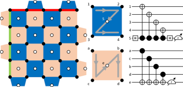
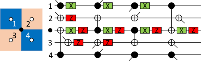
In a rotated surface code patch[20] data qubits are on the vertices of a square grid, while ancilla qubits in the middle of the faces, as shown in Fig. 1.
A logical qubit is encoded in the collective quantum state of the data qubits, more precisely into the so-called logical subspace: the eigensubspace of the - and -stabilizers, called and ,
| (1) |
Stabilizers are and parity checks on the data qubits at the corners of the corresponding faces; their measurement can detect local Pauli errors. These measurements are realized via a syndrome extraction circuit which entangles data qubits with ancillas, as in Fig. 1.
Logical operators of the surface code, also shown in Fig. 1, can be defined as
| (2) |
These commute with all the stabilizers and act as Pauli operators in the logical subspace. Note that the above definition is not unique: equivalently valid logical operators can be obtained by multiplied the and defined above with any stabilizers, since this does not change how they act in the logical subspace. The code distance is defined as the minimum weight of logical operators, which is just the linear size of the rotated surface code patch. For Fig. 1, the distance is .
2.1 Characterizing the noisy logical identity channel
The noisy logical identity channel describes what happens to an idling logical qubit, if errors affect the physical qubits of the error correcting code. The error model will be detailed in the next Section. In the case of incoherent physical errors the channel reads,
| (3) |
with the parameters describing the probabilities of Pauli X, Y, Z errors. The total logical failure rate is ,
| (4) |
Characterization of the noisy logical identity channel is the (numerical) computation of the parameters , which depend on both the details of the quantum error correcting code and the errors affecting the physical qubits.
We fully characterize the noisy logical identity channel of a logical qubit encoded in a single surface code patch under circuit-level Pauli noise. We perform efficient Clifford simulations with the Python package STIM [21] of ideal memory experiments. The numerical data is available at [22]. Our approach, as shown in Fig.2, is as follows. We first ideally (with a circuit without noise) initialize the patch in one of the logical Clifford states, or , then measure the stabilizers through noisy syndrome extraction circuits, times. At the end we perform a perfect stabilizer measurement round to ensure the quantum state is left in the logical subspace up to a correction operator (see next paragraph). Finally, we measure all of the data qubits in the appropriate basis (in accordance with the initialized state) and extract the eigenvalue of the appropriate logical Pauli operator, or .
For the decoding, i.e., to decide a correction operator based on the stabilizer measurement outcomes, we used the minimum weight perfect matching approach [3, 23] via PyMatching [24, 25]. We used STIM to decompose the detector error model into weighted and matching graphs, where the weights display the probabilities in the circuit-level error model.

Note that we do not model in detail the preparation of the initial state – this is not relevant for our purpose. In principle, the preparation of logical Clifford states and the measurement of logical Pauli operators can be done fault tolerantly [26]. However, we would like to characterize the logical identity channel itself and not the noisy memory experiments, so we exclude noise in the initialization and logical measurement processes. In other words, our goal in this work is to find the optimal strategy for protecting logical quantum information encoded in idling surface code patches while some other patches may undergo logical operations by any of the proposed approaches [27, 28, 29, 30, 31, 32].
3 Error model

We consider three types of errors during quantum error correction rounds, to give a rough description of noise in current quantum devices [5, 12]: idling errors, describing the dissipative dynamics of data qubits; gate errors, modeling the noisy quantum gates; and readout errors, describing imperfect measurements. Among the error types we neglect are leakage errors, correlated errors (these two can be efficiently suppressed with various physical-level solutions [33, 34, 35, 36]), and crosstalk [37, 38] (which we plan to investigate in follow-up work). We also neglect coherence in the errors by considering only random Pauli error channels. This approximation (obtained, e.g., using Pauli twirling) is necessary for the large scale numerical simulations[39, 40]. Neglecting coherence in the physical errors is generally believed to be a reasonable approximation, as supported by analytical[16, 15], numerical [17, 18, 19], and experimental [5] work.
Idling errors describe the dissipative dynamics of qubits. They are here modeled based on the amplitude and phase damping channel [41], characterized by two time scales and : the relaxation and pure dephasing times. The corresponding Lindblad equation in the rotating frame reads:
| (5) |
After solving Eq. 3 and applying the Pauli twirl approximation we get
| (6) |
with time dependent Pauli error probabilities,
| (7) | ||||
| (8) | ||||
| (9) |
Here is the rate of dephasing [42].
In the numerical simulations we apply idling errors via Eq. 6 on the data qubits, during the time when the ancilla qubits are being measured and reinitialized, see Fig.3. We approximate this time as in each cycle, where is the total time of the of memory experiment, and is the number of stabilizer measurement rounds. Our basic assumption is that the measurement time is much longer than gate times, which is realistic in current devices [5, 12], thus we neglect the dissipative dynamics of qubits during gate operations.
Gate errors are errors occuring during imperfect quantum gates, whose microscopic model depends very much on the implementation of the gate. We thus use a generic approach: a single-qubit depolarizing channel after each single qubit quantum gate, and a two-qubit depolarizing channel after each two-qubit quantum gate. These channels read:
| (10) | ||||
| (11) |
where is the single qubit identity operator.
Readout errors model faulty measurements, which we treat on the phenomenological level: ideal measurements with possibly erroneously recorded results. The measurement outcome can suffer a classical bit-flip during the readout, therefore, we record the wrong measurement outcome with probability ,
| (12) |
and correspondingly . In Fig. 3 a segment of the noisy syndrome extraction circuit is shown, displaying all three error mechanisms.
4 Optimal number of stabilizer measurement rounds
We ran extensive numerical simulations to characterize the logical identity channel for a broad spectrum of parameters: idling error time scales , , gate error parameter , readout error probability , and code distance . We identified an optimal number of measurement rounds , for each set of parameters, where the logical failure rate is minimal. In this Section we give a qualitative explanation, and the numerical results, of how depends on different parameters. Finally, we discuss the implications of our results for two promising experimental platforms: superconducting qubits and neutral atoms.
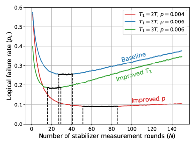
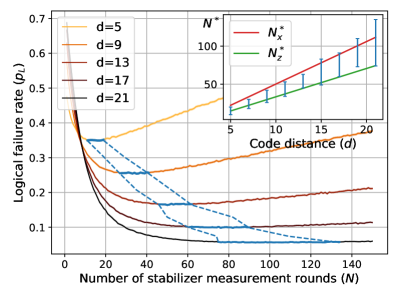
We start with a qualitative explanation why one can expect that there is an optimal number of stabilizer measurement rounds, , to be performed during a fixed time , to minimize the logical failure rate . With few measurement rounds, idling errors dominate the error budget, thus, decreasing increases the chance that idling errors accumulate to cause an unobserved logical error. With many measurement rounds, gate and readout errors dominate the error budget, thus, increasing increases the chance of a logical error. Examples of curves showing this behaviour are depicted in Fig.4.
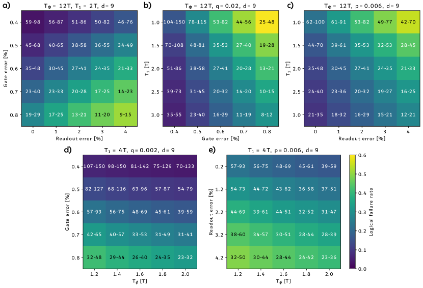
It is quite intuitive to understand qualitatively how the optimal number of stabilizer measurement rounds, , depends on the noise parameters. For higher quality qubits (longer and times) is smaller, because fewer noisy rounds are sufficient to suppress the effect of idling errors. Conversely, for more precise gates and measurements (smaller and ), is larger, because each stabilizer measurement round introduces less noise, making it beneficial to perform more rounds. Numerical simulations confirm these intuitive expectations as shown in Fig. 6. We also find, as in Fig. 4, that the logical failure rate curves are flat around the minima. This results in a large uncertainty in , a roughly identical performance in a wide range of .
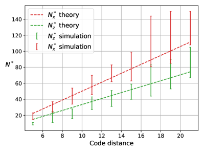
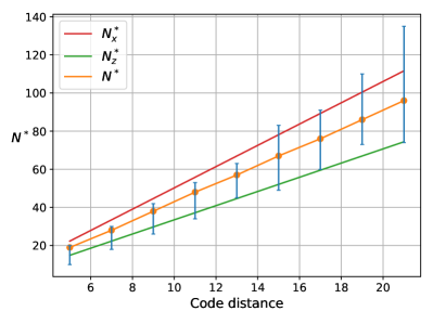
We find that the optimal number of stabilizer measurement rounds also depends on the code distance: increases as the surface code patch is scaled up, see Fig.5. To understand this behaviour we approximate the probability of logical and errors with the contributions from the minimum weight error strings,
| (13) |
Here is some function of the code distance , but independent of , and is independent of both and . The factor is the multiplicity of error strings of weight , composed of data qubit errors. These errors originate from idling errors with probabilities (for logical errors) or (for logical errors), and from gate errors with probability . By counting the possible error events (see Appendix A) we estimate as . In Eq, (13) we neglect ancilla qubit errors (originating from readout errors and gate errors affecting ancilla qubits), because these usually do not contribute to minimum weight error strings. A more detailed explanation can be found in Appendix A.
By approximating the idling error rates as
| (14) |
and differentiating and separately we derive the optimal numbers of stabilizer measurement rounds for and memory experiments,
| (15) |
We have plotted and as the function of in Fig. 5 for the parameter set , , , , and .
The optimal number of stabilizer measurement rounds lays between and , and increases with , because both and are monotonically increasing functions of . Fig. 5 confirms this behaviour and validates Eq. (15). A more detailed analysis of the dependence of the optimal number can be found in Appendix C. In addition, Eq. (15) verifies the intuitive expectations on the , , and dependence of . To express the effect of readout errors, ancilla qubit errors have to be taken into consideration in Eq. (13) as well.
4.1 Comparison with Current Experiments
In the numerical simulations we assumed that the number of measurement rounds can be increased boundlessly. However, in real devices stabilizer measurements take some time to execute, therefore, it may happen that the optimal number cannot be reached in an experiment.
To compare the theoretically optimal and the experimentally feasible number of stabilizer measurement rounds, we consider two quantum error correction experiments from the last few years, one from Google Quantum AI with superconducting qubits [5] and one from Harvard/QuEra with neutral atoms [12]. The error parameters and the execution times of stabilizer measurement cycles of these experiments are summarized in Tab.1.
| Superconducting qubits [5] | Neutral atoms [12] | |
| s | s | |
| s | s | |
| Cycle time | ns | ms |
In our previous choice of parameters in Fig. 6, the relaxation-dominated family of parameter sets () corresponds to superconducting qubits for experiment time s, while the dephasing-dominated family of parameter sets () corresponds to neutral atoms for experiment time s.
While the optimal numbers of stabilizer measurement rounds are of the same order of magnitude for both types of devices (see Fig.6), the experimentally feasible error correction rounds differ significantly. With the superconductor experiment, under s at most stabilizer measurement rounds can be performed, in contrast to that on the neutral atom based quantum device, under s at most rounds. Consequently, the optimal strategy differs for these two devices: For (Fig. 6), for superconducting qubits it is beneficial to do the maximum number of measurement rounds with no idling time, however, for neutral atoms, measuring the stabilizers less frequently is suggested leaving idling time in between for optimal performance.
Although above we discussed the case of a fix idling time , we believe our conclusions regarding the usefulness of idling time between stabilizer measurements are valid more generally. If the errors are rare enough it is reasonable to assume that logical failure rate is proportional to the number of stabilizer measurement rounds with fixed error rates, i.e.,
| (16) |
Therefore, the logical failure rate over unit time, , does not explicitly depend on or , only on the combination . As a consequence the optimal frequency of interventions minimizes this failure rate, meaning that our findings are valid for arbitrary idling time. This is true using the logical failure rate over unit time as the efficiency metric, assuming the rarity of error strings holds as per Eq. (16).
5 Conclusion
In this work we numerically characterized the logical noise channel of an idling surface code patch across various code distances, number of stabilizer measurement rounds, and noise parameters. For each set of noise parameters and code distances, we determined an optimal number for stabilizer measurement rounds, , that maximizes the performance of the surface code patch during a fixed idling time. Our circuit-level noise model incorporated both time-dependent dynamic errors, amplitude and phase damping of data qubits, and time-independent static gate and readout errors.
Our results indicate that decreases with higher qubit quality, while it increases with higher gate quality and larger code sizes. We also explored the applicability of our findings to superconducting and neutral atom devices, revealing distinct optimal strategies for these two architectures. Specifically, for superconducting qubits, the optimal strategy involves performing the maximum feasible number of stabilizer measurement rounds, whereas for neutral atoms, the optimal number is significantly lower than the maximum feasible.
Including more sophisticated errors, such as leakage [33], crosstalk [37, 38], or correlated errors [36] would be an interesting extension of our work, as would considering more parameters to optimize on (e.g., code, code distance, reset after measurements) to get the best performance, as in [43, 44].
We believe our results will be valuable for instrumentalists aiming to further optimize the performances of logical qubits encoded into quantum error-correcting codes.
Our data is available at [22].
6 Acknowledgement
This research was supported by the Ministry of Culture and Innovation and the National Research, Development and Innovation Office within the Quantum Information National Laboratory of Hungary (Grant No. 2022-2.1.1-NL-2022-00004), and by the Horizon Europe research and innovation programme of the European Union through the HORIZON-CL4-2022- QUANTUM01-SGA project 101113946 OpenSuperQPlus100 of the EU Flagship on Quantum Technologies. We acknowledge the support of the Wigner Research Centre for Physics’ trainee program.
References
- [1] A.Yu. Kitaev. “Fault-tolerant quantum computation by anyons”. Annals of Physics 303, 2–30 (2003).
- [2] Austin G. Fowler, Matteo Mariantoni, John M. Martinis, and Andrew N. Cleland. “Surface codes: Towards practical large-scale quantum computation”. Physical Review A86 (2012).
- [3] Eric Dennis, Alexei Kitaev, Andrew Landahl, and John Preskill. “Topological quantum memory”. Journal of Mathematical Physics 43, 4452–4505 (2002).
- [4] Chenyang Wang, Jim Harrington, and John Preskill. “Confinement-Higgs transition in a disordered gauge theory and the accuracy threshold for quantum memory”. Annals of Physics 303, 31–58 (2003).
- [5] Google Quantum AI. “Suppressing quantum errors by scaling a surface code logical qubit”. Nature 614, 676 – 681 (2022).
- [6] Google Quantum AI and Collaborators. “Quantum error correction below the surface code threshold” (2024). arXiv:2408.13687.
- [7] Dolev Bluvstein, Harry Levine, Giulia Semeghini, Tout T. Wang, Sepehr Ebadi, Marcin Kalinowski, Alexander Keesling, Nishad Maskara, Hannes Pichler, Markus Greiner, Vladan Vuletić, and Mikhail D. Lukin. “A quantum processor based on coherent transport of entangled atom arrays”. Nature 604, 451–456 (2022).
- [8] Sebastian Krinner, Nathan Lacroix, Ants Remm, Agustin Di Paolo, Elie Genois, Catherine Leroux, Christoph Hellings, Stefania Lazar, Francois Swiadek, Johannes Herrmann, et al. “Realizing repeated quantum error correction in a distance-three surface code”. Nature 605, 669–674 (2022).
- [9] J. F. Marques, B. M. Varbanov, M. S. Moreira, H. Ali, N. Muthusubramanian, C. Zachariadis, F. Battistel, M. Beekman, N. Haider, W. Vlothuizen, A. Bruno, B. M. Terhal, and L. DiCarlo. “Logical-qubit operations in an error-detecting surface code”. Nature Physics 18, 80–86 (2021).
- [10] Youwei Zhao et al. “Realization of an error-correcting surface code with superconducting qubits”. Physical Review Letters129 (2022).
- [11] M. H. Abobeih, Y. Wang, J. Randall, S. J. H. Loenen, C. E. Bradley, M. Markham, D. J. Twitchen, B. M. Terhal, and T. H. Taminiau. “Fault-tolerant operation of a logical qubit in a diamond quantum processor”. Nature 606, 884–889 (2022).
- [12] Dolev Bluvstein et al. “Logical quantum processor based on reconfigurable atom arrays”. Nature (2023).
- [13] Jiaxuan Zhang, Zhao-Yun Chen, Yun-Jie Wang, Bin-Han Lu, Hai-Feng Zhang, Jia-Ning Li, Peng Duan, Yu-Chun Wu, and Guo-Ping Guo. “Demonstrating a universal logical gate set on a superconducting quantum processor” (2024). arXiv:2405.09035.
- [14] Bence Hetényi and James R Wootton. “Creating entangled logical qubits in the heavy-hex lattice with topological codes” (2024). arXiv:2404.15989.
- [15] Joseph K Iverson and John Preskill. “Coherence in logical quantum channels”. New Journal of Physics 22, 073066 (2020).
- [16] Stefanie J. Beale, Joel J. Wallman, Mauricio Gutiérrez, Kenneth R. Brown, and Raymond Laflamme. “Quantum error correction decoheres noise”. Physical Review Letters 121, 190501 (2018).
- [17] Sergey Bravyi, Matthias Englbrecht, Robert König, and Nolan Peard. “Correcting coherent errors with surface codes”. npj Quantum Information4 (2018).
- [18] Áron Márton and János K. Asbóth. “Coherent errors and readout errors in the surface code”. Quantum 7, 1116 (2023).
- [19] Dávid Pataki, Áron Márton, János K. Asbóth, and András Pályi. “Coherent errors in stabilizer codes caused by quasistatic phase damping” (2024). arXiv:2401.04530.
- [20] H. Bombin and M. A. Martin-Delgado. “Optimal resources for topological two-dimensional stabilizer codes: Comparative study”. Physical Review A76 (2007).
- [21] Craig Gidney. “Stim: a fast stabilizer circuit simulator”. Quantum 5, 497 (2021).
- [22] Áron Márton and János K. Asbóth. “Data for "Optimal number of stabilizer measurement rounds in an idling surface code patch" 10.5281/zenodo.13320275” (2024).
- [23] Austin G. Fowler. “Minimum weight perfect matching of fault-tolerant topological quantum error correction in average parallel time” (2014). arXiv:1307.1740.
- [24] Oscar Higgott. “Pymatching: A python package for decoding quantum codes with minimum-weight perfect matching”. ACM Transactions on Quantum Computing 3, 1–16 (2022).
- [25] Oscar Higgott and Craig Gidney. “Sparse blossom: correcting a million errors per core second with minimum-weight matching” (2023). arXiv:2303.15933.
- [26] Craig Gidney. “Inplace access to the surface code y basis”. Quantum 8, 1310 (2024).
- [27] Dominic Horsman, Austin G Fowler, Simon Devitt, and Rodney Van Meter. “Surface code quantum computing by lattice surgery”. New Journal of Physics 14, 123011 (2012).
- [28] Benjamin J. Brown, Katharina Laubscher, Markus S. Kesselring, and James R. Wootton. “Poking holes and cutting corners to achieve Clifford gates with the surface code”. Physical Review X7 (2017).
- [29] Sergey Bravyi and Alexei Kitaev. “Universal quantum computation with ideal Clifford gates and noisy ancillas”. Physical Review A71 (2005).
- [30] Benjamin J. Brown. “A fault-tolerant non-Clifford gate for the surface code in two dimensions”. Science Advances 6, eaay4929 (2020).
- [31] Daniel Litinski. “A game of surface codes: Large-scale quantum computing with lattice surgery”. Quantum 3, 128 (2019).
- [32] Héctor Bombín, Chris Dawson, Ryan V. Mishmash, Naomi Nickerson, Fernando Pastawski, and Sam Roberts. “Logical blocks for fault-tolerant topological quantum computation”. PRX Quantum4 (2023).
- [33] Kevin C. Miao et al. “Overcoming leakage in quantum error correction”. Nature Physics 19, 1780 – 1786 (2022).
- [34] Nathan Lacroix et al. “Fast flux-activated leakage reduction for superconducting quantum circuits” (2023). arXiv:2309.07060.
- [35] J. F. Marques et al. “All-microwave leakage reduction units for quantum error correction with superconducting transmon qubits”. Phys. Rev. Lett. 130, 250602 (2023).
- [36] Matt McEwen, Kevin C. Miao, Juan Atalaya, Alex Bilmes, Alex Crook, Jenna Bovaird, John Mark Kreikebaum, Nicholas Zobrist, Evan Jeffrey, Bicheng Ying, Andreas Bengtsson, Hung-Shen Chang, Andrew Dunsworth, Julian Kelly, Yaxing Zhang, Ebrahim Forati, Rajeev Acharya, Justin Iveland, Wayne Liu, Seon Kim, Brian Burkett, Anthony Megrant, Yu Chen, Charles Neill, Daniel Sank, Michel Devoret, and Alex Opremcak. “Resisting high-energy impact events through gap engineering in superconducting qubit arrays” (2024). arXiv:2402.15644.
- [37] Andreas Ketterer and Thomas Wellens. “Characterizing crosstalk of superconducting transmon processors”. Physical Review Applied20 (2023).
- [38] Mohan Sarovar, Timothy Proctor, Kenneth Rudinger, Kevin Young, Erik Nielsen, and Robin Blume-Kohout. “Detecting crosstalk errors in quantum information processors”. Quantum 4, 321 (2020).
- [39] Daniel Gottesman. “The Heisenberg representation of quantum computers” (1998). arXiv:quant-ph/9807006.
- [40] Scott Aaronson and Daniel Gottesman. “Improved simulation of stabilizer circuits”. Physical Review A 70, 052328 (2004).
- [41] Michael A. Nielsen and Isaac L. Chuang. “Quantum computation and quantum information: 10th anniversary edition”. Cambridge University Press. (2010).
- [42] Yu Tomita and Krysta M. Svore. “Low-distance surface codes under realistic quantum noise”. Physical Review A90 (2014).
- [43] Avimita Chatterjee, Debarshi Kundu, and Swaroop Ghosh. “Mits: A quantum sorcerer stone for designing surface codes” (2024). arXiv:2402.11027.
- [44] György P. Gehér, Marcin Jastrzebski, Earl T. Campbell, and Ophelia Crawford. “To reset, or not to reset – that is the question” (2024). arXiv:2408.00758.
Appendix A Minimum weight error strings
We approximated the probabilities of logical and errors with the contributions coming from the minimum weight error strings in Eq. (13). Here, we provide a detailed explanation of this approximation, and also motivate our choice of neglecting error strings that contain ancilla qubit errors.
Ordering the CNOT gates properly (see Fig. 3) does not reduce the code distance at the circuit level. So, at least error events are required for an undetected logical error. As a consequence the minimum number of independent error events that can cause a logical error (after correction) is . We call sets of error events that lead to a logical error and consist of elements, minimum weight error strings.
There are two types of minimum weight error strings: the first one contains error events only on data qubits, while the second one contains one error event on an ancilla qubit and error events on data qubits. The minimum weight error strings of the second type only count as minimum weight error strings (they only get corrected "wrongly") if the correction has a smaller weight than the error, which happens if the error events on the ancilla qubits have a smaller probability than on the data qubits. For large enough measurement rounds the error events on the ancilla qubits are more likely, therefore, we neglected the contribution of the minimum weight error strings of the second type. However, a more detailed analysis should contain the contribution of these error strings as well.
The error events on data qubits originate from gate or idling errors, therefore, the probabilities can be written in a form which we already used in Eq. (13),
| (17) |
here we neglected higher order terms.
Appendix B Counting error events
To estimate (the weight of gate errors in physical error probability) we approximately counted the possible error events that can occur during one stabilizer measurement round. A data qubit participates in 4 CNOT operations which can cause data qubit error events. Also, gate errors on ancilla qubits can propagate to a data qubit from the other 3 CNOT gates. Therefore, the total number of data qubit error events is 7 in both the and cases. Possible error events are shown in Fig. 7. The probability of an or data qubit error event, caused by a gate error, is , because two-qubit Pauli errors consist an or error on a given (first or second) qubit. Therefore,
| (18) |
Appendix C The dependence of
Analytical expressions can be derived for the optimal number of stabilizer measurement rounds for and memory experiments separately; see Eq. (15). These expressions are derived from the minimum weight error string contributions in the logical failure rate, Eq. (13). To see how the theoretically derived expressions of and match with the numerically determined optimal intervals of X and Z memory experiments, we have plotted these optimal intervals separately for X and Z memory experiments in Fig. 8.
Considering the minimum weight contributions in and , as in Eq. (13), not only offers analytical expressions for and , but also gives a theoretical prediction for , the minimum of . We numerically determined the minima of the logical failure rate (contains only minimum weight error string contributions) for the relevant set of parameters and plotted it in Fig. 9, together with , and the optimal intervals. In Fig. 9 the line of lays between and and matches with the numerically determined optimal intervals, as mentioned in the main text.