Chirped DFT-s-OFDM: A new single-carrier waveform with enhanced LMMSE noise suppression
Abstract
In this correspondence, a new single-carrier waveform, called chirped discrete Fourier transform spread orthogonal frequency division multiplexing (DFT-s-OFDM), is proposed for the sixth generation of communications. By chirping DFT-s-OFDM in the time domain, the proposed waveform maintains the low peak-to-average-power ratio (PAPR) of DFT-s-OFDM. Thanks to full-band transmission and symbols retransmission enabled by chirping and discrete Fourier transform (DFT) precoding, the proposed waveform can enhance noise suppression of linear minimum mean square error equalization. Its bit error rate (BER) upper bound and diversity order are derived using pairwise error probability. Simulation results confirm that the proposed waveform outperforms the state-of-the-art waveforms in terms of BER, output signal-to-noise-ratio, and PAPR.
I Introduction
Transmission waveform has been regarded as one of important components in every generation of communications, enabling increased capacity and data rates, improved spectral and power efficiency, new applications, etc. Orthogonal frequency division multiplexing (OFDM) was adopted for downlink transmissions in the fourth (4G) and fifth generations (5G) of communications. For the sake of low peak-to-average-power-ratio (PAPR), discrete Fourier transform spread OFDM (DFT-s-OFDM) [1] was selected for uplink transmissions. However, they may be not suitable for high-mobility communications in the sixth generation (6G) of communications. 6G waveform design has thus attracted significant attention from both academia and industry recently.
The 6G waveform candidates in the literature can be classified into three categories: multi-carrier, single-carrier, and multi-carrier chirping. Multi-carrier category includes orthogonal time frequency space (OTFS) [2], orthogonal delay-Doppler division multiplexing (ODDM) [3], frequency-modulated OFDM (FM-OFDM) [4], etc. However, similar to OFDM, OTFS and ODDM based on multi-carrier have high PAPR, making it unsuited for low-power devices. Though FM-OFDM could reduce PAPR, its frequency spectrum utilization with lots of inactive subcarriers is inefficient. Meanwhile, the performance advantages of FM-OFDM over OTFS are not identified. Single-carrier category consists of orthogonal time sequency multiplexing (OTSM), whose PAPR is however as high as that of OTFS [5]. Orthogonal chirping division multiplexing (OCDM) [6] and affine frequency division multiplexing (AFDM) [7] belong to multi-carrier chirping category. AFDM is an enhanced version of OCDM to cater for high-mobility communications. However, they are based on multi-carrier and have high PAPR as well.
In this paper, a new single-carrier waveform called chirped DFT-s-OFDM is proposed for 6G communications. The contributions of this paper are summarized as follows:
- •
-
•
By using chirping and discrete Fourier transform (DFT) precoding, the proposed waveform enables full-band transmission and symbols retransmission, contributing to enhanced noise suppression of linear minimum mean square error (LMMSE) equalization. Simulation results confirm that it outperforms the existing waveforms, e.g., DFT-s-OFDM, AFDM, OTFS, and OFDM, in terms of bit error rate (BER) and output signal-to-noise-ratio (SNR).
-
•
Like multi-carrier chirping waveform, e.g., AFDM, the proposed single-carrier chirping waveform can also achieve full frequency diversity. Its BER upper bound and diversity order are derived based on pairwise error probability (PEP). Simulation results verify that the simulated BER approaches the derived BER upper bound.
This correspondence is organized as follows. The proposed chirped DFT-s-OFDM is described in Section II, followed by its performance analysis in Section III. Sections IV and V provide simulation results and conclusion.
II System Model
II-A Modulation and Demodulation
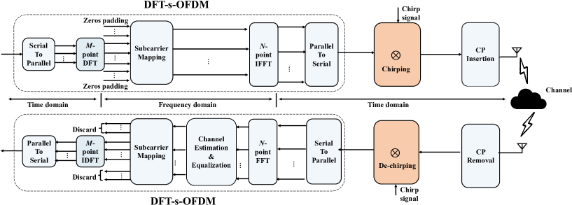
The block diagram of proposed chirped DFT-s-OFDM is illustrated in Fig. 1. At transmitter side, the proposed chirped DFT-s-OFDM includes two main blocks, with DFT-s-OFDM modulation followed by chirping. The un-modulated time-domain data vector of length is denoted as . After -point DFT, the frequency-domain data vector of length is given by , with being -point DFT matrix. After subcarrier mapping, the data vector of length is written as , with being a subcarrier mapping matrix of size (). Interleaved subcarrier mapping with is used in this paper, with being an identity matrix of size . The DFT spreading factor is defined as . Inverse fast Fourier transform (FFT) is then implemented, resulting in time-domain signal , with being -point FFT matrix. The DFT-s-OFDM signal is then chirped with a linear chirp signal of chirp rate , obtaining the chirped DFT-s-OFDM signal denoted as :
| (1) |
with .
A cyclic prefix of length () is appended to before transmission, with being the channel order. is defined as channel gain of -th channel path at -th time instant, with and . Define as the normalized maximum Doppler frequency with respect to subcarrier spacing, with , , , and being carrier frequency, velocity, speed of light, and subcarrier spacing, respectively. is given by
| (2) |
with and () being the channel gain and normalized Doppler shift of -th path. The time-domain circulant channel matrix is expressed as
| (3) |
where and is the forward cyclic-shift matrix defined as (25) of [7].
The received time-domain signal vector of length after the removal of cyclic prefix is expressed as
| (4) |
with w being an additive white Gaussian noise vector of variance . Define . After dechirping and -point FFT, the frequency-domain received signal vector is
| (5) |
OFDM channel estimation and equalization schemes can then be exploited to recover the frequency-domain symbols. The transmitted time-domain data symbols can be recovered by discarding unused subcarriers and performing inverse -point DFT of the estimated frequency-domain symbols.
II-B Time-Frequency Diagram
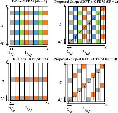
The time-frequency diagrams of DFT-s-OFDM and proposed chirped DFT-s-OFDM are illustrated in Fig. 2, with and . Regarding DFT-s-OFDM with , information symbols are mapped in the time domain in four different colors and then are repeated in the time domain due to DFT precoding, with each symbol occupying the assigned subcarrier bands. The un-assigned subcarrier bands are indicated in white color and can be used by other users for data transmission. A linear chirp signal with chirp rate is used, implying that the frequency is increased by one subcarrier spacing per time instant. After chirping, the data symbols, e.g., in blue and orange color, can hop to the un-assigned subcarrier bands. Thus, the chirped DFT-s-OFDM enables data transmission over the full band, leading to enhanced noise suppression in the frequency domain. Besides, when increases to and each symbol would be repeated times in the time domain, additional noise suppression can be obtained. Fig. 7 in Section IV will confirm that the increase of would reduce output noise power and BER. For the sake of full band transmission, the chirp rate should be properly selected by using , with and being zero or positive integer value.
It is noteworthy that chirp signal was applied with DFT-s-OFDM in [1], which however is used in the frequency domain and at transmitter side only. It also presents limited performance gains over DFT-s-OFDM, especially when linear chirp is used and DFT spreading factor is big [1]. In contrast, chirp signal is used in the time domain at both transmitter side and receiver side for the proposed waveform, referred to as chirping and dechirping in Fig. 1. According to [7], chirping in the time domain would have a greater impact than that in the frequency domain. As will be seen in Section IV, the proposed chirped DFT-s-OFDM with chirping in the time domain would have superior BER and output SNR over DFT-s-OFDM, especially when it has a big DFT spreading factor.
III Performance Analysis
The error performance of proposed chirped DFT-s-OFDM is investigated using PEP analysis of maximum likelihood (ML) equalizer. Then, the output SNR of proposed waveform is derived and analyzed using LMMSE equalizer.
III-A Error Performance Analysis Using ML Equalizer
The system model in (5) can be rewritten as
| (6) |
Denote . The received frequency-domain signal vector is reexpressed as
| (7) |
with and .
Denote as the pairwise error event, where represents the transmitted signal vector and the erroneously detected signal vector using ML equalizer. and are chosen from a certain modulation alphabet, i.e., and , but with . Define . The rank of and its non-zero eigenvalues are denoted as and . Assume each entry in is an independent identically distributed complex Gaussian random variable, i.e., . The SNR for each data symbol is denoted as , i.e., . Following the derivation in [8], the PEP can be expressed as
| (8) |
At high SNR, (8) can be approximated as
| (9) |
The average BER can then be obtained by using the union bound technique [8] as follows:
| (10) |
with being the number of bits in difference between and . The diversity order of chirped DFT-s-OFDM is given by
| (11) |
By calculating using (11), it is found to be equal to the number of channel paths.
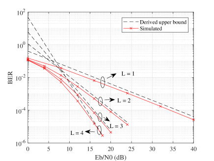
Fig. 3 shows the derived BER upper bound (10) and simulated BER of proposed chirped DFT-s-OFDM using ML equalizer. The DFT size and IFFT size of chirped DFT-s-OFDM are and . The maximum Doppler frequency, velocity, and subcarrier spacing are , , and . Binary phase shift keying (BPSK) modulation is adopted. According to Fig. 3, the simulated BER is close to the derived BER upper bound especially at high SNRs. The slope of BER curves corresponds to the diversity order of chirped DFT-s-OFDM, which is found to be the number of channel paths and is consistent with (11).
III-B Output SNR Analysis Using LMMSE Equalizer
By letting , (5) is rewritten as
| (12) |
can be estimated using LMMSE equalizer as
| (13) |
According to [9], the output SNR of chirped DFT-s-OFDM using LMMSE equalizer can be expressed as
| Output SNR | ||||
| (14) |
where , and indicate the expectation and trace operation.
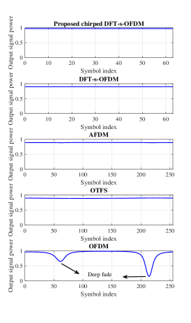
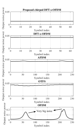
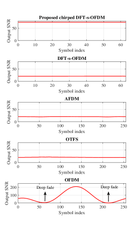
Figs. 4a, 4b, and 4c depict the output signal power, output noise power, and output SNR using LMMSE equalizer of proposed chirped DFT-s-OFDM, in comparison to existing waveforms. According to Fig. 4a, the proposed waveform has slightly higher output signal power than DFT-s-OFDM, AFDM, and OTFS, while OFDM has deep fades with signal power reduced significantly. In Fig. 4b, the proposed chirped DFT-s-OFDM has the lowest output noise power. DFT-s-OFDM, AFDM, and OTFS have similar noise power while OFDM has two spikes with very high noise power. In Fig. 4c, the proposed chirped DFT-s-OFDM has highest output SNR and the output SNR remains nearly identical at each symbol. The output SNRs of DFT-s-OFDM, AFDM, and OTFS are close and roughly half of that of chirped DFT-s-OFDM. Though OFDM has good output SNR at some symbols, its deep fades greatly degrade the overall performance. In conclusion, the proposed chirped DFT-s-OFDM can enhance noise suppression of LMMSE equalization, and thus, would contribute to enhanced communication performance.
IV Simulation Results
The communication performances of proposed chirped DFT-s-OFDM are studied and compared with the existing waveforms, e.g., DFT-s-OFDM, AFDM, OTFS, and OFDM. Unless otherwise stated, the values of simulation parameters are set in the following. The IFFT size of chirped DFT-s-OFDM, DFT-s-OFDM, AFDM, and OFDM is . The DFT size of chirped DFT-s-OFDM and DFT-s-OFDM is , leading to the DFT spreading factor of . The chirp rate is . The carrier frequency and subcarrier spacing are and . The -path equal-gain channel is assumed. The velocity is , corresponding to Doppler frequency of . For OTFS, the numbers of delay grids and Doppler grids are and . Quadrature phase shift keying (QPSK) modulation and LMMSE equalizer are adopted.
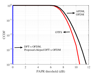
Fig. 5 shows the complementary cumulative distribution function (CCDF) of PAPRs of proposed chirped DFT-s-OFDM and existing waveforms. The proposed waveform by multiplying chirp signal with DFT-s-OFDM preserves the low PAPR of DFT-s-OFDM. Their PAPR is much lower than that of multi-carrier waveforms, e.g., AFDM, OTFS, and OFDM.
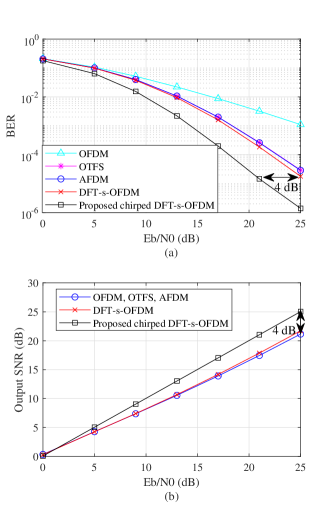
Fig. 6 presents the BER and output SNR of proposed chirped DFT-s-OFDM, compared to DFT-s-OFDM, AFDM, OTFS, and OFDM. Thanks to enhanced noise suppression discussed in Subsections II-B and III-B, the proposed chirped DFT-s-OFDM outperforms the existing waveforms in terms of BER and output SNR, with around gain over AFDM, OTFS, and DFT-s-OFDM. Though OFDM has output SNR that is as good as that of OTFS and AFDM, it has deep fades as shown in Fig. 4. Meanwhile, it cannot exploit frequency diversity, and thus, its BER is worst in Fig. 6a).
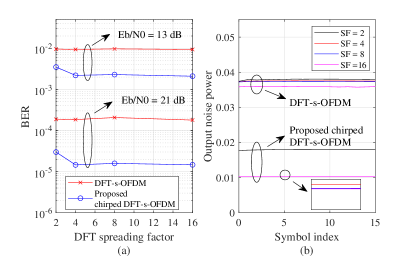
Fig. 7a) studies the impact of DFT spreading factor on BER of DFT-s-OFDM and proposed chirped DFT-s-OFDM. The BER of DFT-s-OFDM would not obviously enhance with DFT spreading factor. In contrast, for the proposed chirped DFT-s-OFDM, there is an obvious BER improvement especially when DFT spreading factor increases from to . This is because the increase of DFT spreading factor tends to enhance noise suppression as can be seen in Fig. 7b). As discussed in Subsection II-B, the enhanced noise suppression results from full band transmission and symbols retransmission enabled by chirping and DFT precoding, respectively.
V Conclusion
In this correspondence, a new single-carrier waveform called chirped DFT-s-OFDM has been proposed for 6G communications. The new waveform by chirping DFT-s-OFDM in the time domain maintains the low PAPR of DFT-s-OFDM. Thanks to the full band transmission and symbols retransmission enabled by chirping and DFT precoding, the proposed waveform enables enhanced noise suppression of LMMSE equalization. It presents higher output SNR and lower BER than the state-of-the-art waveforms, including DFT-s-OFDM, AFDM, OTFS, and OFDM. In addition, the PEP analysis and simulation results confirm that the proposed waveform can achieve full frequency diversity.
References
- [1] A. Sahin, N. Hosseini, H. Jamal, S. S. M. Hoque, and D. W. Matolak, “DFT-Spread-OFDM-based chirp transmission,” IEEE Communications Letters, vol. 25, no. 3, pp. 902–906, 2021.
- [2] Y. Liu, Y. L. Guan, and D. González G., “Near-optimal BEM OTFS receiver with low pilot overhead for high-mobility communications,” IEEE Trans. Commun., vol. 70, no. 5, pp. 3392–3406, 2022.
- [3] H. Lin and J. Yuan, “Orthogonal delay-doppler division multiplexing modulation,” IEEE Trans. Wireless Commun., vol. 21, no. 12, pp. 11 024–11 037, 2022.
- [4] J. Lorca Hernando and A. G. Armada, “Frequency-modulated OFDM: A new waveform for high-mobility wireless communications,” IEEE Trans. Commun., vol. 71, no. 1, pp. 540–552, 2023.
- [5] B. V. S. Reddy, C. Velampalli, and S. S. Das, “Performance analysis of multi-user OTFS, OTSM, and single carrier in uplink,” IEEE Trans. Commun., vol. 72, no. 3, pp. 1428–1443, 2024.
- [6] X. Ouyang and J. Zhao, “Orthogonal chirp division multiplexing,” IEEE Trans. Commun., vol. 64, no. 9, pp. 3946–3957, 2016.
- [7] A. Bemani, N. Ksairi, and M. Kountouris, “Affine frequency division multiplexing for next generation wireless communications,” IEEE Trans. Wireless Commun., vol. 22, no. 11, pp. 8214–8229, 2023.
- [8] Y. Ge, Q. Deng, D. González G., Y. L. Guan, and Z. Ding, “OTFS signaling for SCMA with coordinated multi-point vehicle communications,” IEEE Trans. Veh. Technol., vol. 72, no. 7, pp. 9044–9057, 2023.
- [9] Y. Jiang, M. K. Varanasi, and J. Li, “Performance analysis of ZF and MMSE equalizers for MIMO systems: An in-depth study of the high SNR regime,” IEEE Trans. Inf. Theory, vol. 57, no. 4, pp. 2008–2026, 2011.