Interlayer Dzyaloshinskii-Moriya interactions induced via non-linear phononics in bilayer van der Waals materials
Abstract
We theoretically study the impact of light-driven structural changes via nonlinear phononics on the magnetic order of untwisted bilayer van der Waals materials. We consider an illustrative example of the AA-stacked bilayer honeycomb lattice and show that high-intensity light in resonance with selected phonons induces large amplitude phonon displacements that modify the magnetic Hamiltonian of the system. We performed a group theory analysis to identify the vibrational modes of the honeycomb bilayer and the nonlinear couplings among them in the strongly driven regime. We find that the structural changes in the strongly driven regime lower the symmetry relative to the equilibrium lattice and produce changes in the magnetic interactions between the local moments. In particular, the lattice symmetry changes permit a non-zero interlayer Dzyaloshinskii-Moriya interaction that induces a magnetic state with canted local moments. Using a spin-wave analysis about the new magnetic configuration we study the corresponding changes in the magnon spectrum and identify a protocol for engineering topological band transitions using a combination of nonlinear phononics and an external magnetic field. Our work suggests a strategy to induce interlayer Dyzaloshinskii-Moriya interactions in a class of layered van der Waals materials, the effect of which is to modify the magnetic ground state, magnon dispersions, and related band geometric properties, including topological invariants.
I Introduction
The allowed magnetic exchange interactions on a particular lattice are constrained by symmetry. The Dzyaloshinskii-Moriya interaction (DMI),
| (1) |
where is a spin on site in the lattice and is a lattice symmetry-determined vector depending on the positions of site and , is permitted in the absence of a center of inversion[1, 2], either in bulk or at an interface [3, 4]. As seen from Eq.(1), the DMI tends to favor spin configurations where local moments exhibit a perpendicular relative orientation, in contrast to the collinear orientations favored by Ising exchange interactions, and Heisenberg/XY exchange interactions in the absence of frustration. (Frustration can produce noncollinear ground state spin arrangements in spin Hamiltonians with a continuous spin rotational symmetry, such as occurs on the triangular lattice with nearest-neighbor antiferromagnetic Heisenberg interactions [5, 6].) Through competition with Heisenberg exchange interactions, the DMI can lead to interesting magnetic textures, such as skyrmions [7], which could find applications in spintronics [8, 9, 10].
The majority of studies on magnetic systems with a DMI have focused on the intralayer DMI, but recent theoretical predictions [11], followed by experimental realizations [12, 13, 14, 15], have shown the emergence of interlayer DMI (IL-DMI) in layered magnetic systems. Furthermore, experiments have demonstrated the possibility of controlling the IL-DMI in synthetic antiferromagnets via electric currents [16], which could enable the manipulation of three-dimensional magnetic textures [17].
In this work, we explore how to generate an IL-DMI with optical control, namely by irradiating quantum materials with lasers, which previously has been demonstrated to induce and control various ordered states [18, 19, 20, 21, 22, 23]. In particular, the laser excitation of infrared lattice vibrations has allowed researchers to predict, induce and manipulate magnetic states [24, 25, 26] (including magnetic order switching [27, 28]), ferroelectric states [29, 30, 31, 32, 33], and enhance superconductivity in organic materials [34, 35, 36, 37, 38, 39], cuprates [40, 41, 42, 43, 44] as well as in more traditional BCS systems [45]. Additionally, theoretical proposals have shown that cavities, instead of lasers, could also lead to phonon-induced ordered electronic states [46, 47, 48, 49]. The laser illumination strategy has the additional advantage of ultrafast (and reversible) control of the magnetic Hamiltonian.
Prior theoretical works have shown that light coupled directly to the electronic or spin degrees of freedom can induce and control the (intralayer) DMI in 2D magnetic materials described by the Kane-Mele-Hubbard model [50], and in multiferroics [51]. After analyzing crystallographic point groups in two-dimensional insulating magnets, a subsequent symmetry analysis showed that light-induced symmetry lowering universally results in a DMI [52]. However, introducing a mechanism that allows one to control the intralayer and IL-DMI interaction via the lattice vibrations could bypass (or at least minimize) the heating effects associated with such direct laser-electron coupling.
We consider an insulating AA-stacked bilayer honeycomb lattice with localized classical moments with collinear order from Heisenberg interactions. In equilibrium, symmetry considerations forbid an IL-DMI between nearest neighbors. We show that applying an intense enough laser in resonance with specific infrared active phonons lowers the symmetry of the non-equilibrium structure via non-linear coupling with Raman active phonons. The out-of-equilibrium lattice structure permits a non-zero IL-DMI between nearest neighbors, which, in turn, leads to a canted magnetic state. We also analyze the corresponding changes to the magnon spectrum as well as the magnon band topology.
The remainder of the paper is organized as follows. In Sec.II.2, we introduce a bilayer honeycomb lattice model and perform a symmetry (group theory) analysis to identify the normal modes of lattice vibrations (phonons) and their non-linear interactions. We then select the phonons that break the symmetry which forbids the existence of IL-DMI in equilibrium to allow the IL-DMI in the out-of-equilibrium lattice configuration. In Sec. III, we introduce the equilibrium magnetic Hamiltonian and the form of the phonon-induced IL-DMI. We perform a spin-wave (magnon) analysis showing the effects of the IL-DMI. We suggest possible material candidates to observe the effects discussed in our work. Finally, in Sec. IV, we present the main conclusions of our work.
II IL-DMI from nonlinear phononics
II.1 Brief review of nonlinear phononics
We begin our discussion by studying phonons, which are quantized modes of lattice vibrations. In a system with inversion symmetry they can be categorized into two types. One type is infrared active (IR) modes which are directly related to the electric dipole moment and thus can be directly excited by an electric field with the correct frequency. The other type is Raman modes, which are related to the polarizability of the phonon mode. In a centrosymmetric crystal, only infrared active modes can be directly controlled by an electric field, while Raman modes require a second order photon process to excite [53]. However, Raman active modes can be controlled indirectly via non-linear couplings to infrared active modes - an approach called nonlinear phononics [32, 54]. In particular, the nonlinear couplings between the two modes can be used to shift the equilibrium position of the Raman modes which are typically lower in frequency by looking at the average effect of the “fast” IR active modes. This approach allows one to modify lattice symmetries and enable new forms of magnetic exchange terms in a local moment Hamiltonian on the lattice.
In our work we will assume a frozen phonon picture as well as a Born-Oppenheimer approximation [55] for electrons responding to the transient lattice changes from light. This is well justified based on the light mass of the electrons relative to the lattice ions as well as the characteristic frequencies of phonons compared to electron energies (phonon frequencies are typically two orders of magnitude or more smaller). We also treat the interaction between light and infrared active modes, as well as the interaction between phonon modes themselves, as classical.
One can understand the qualitative effects from nonlinear phononics in a simple heuristic model: When one takes into account up to cubic order terms in the lattice displacements the effective potential of a single interacting IR and Raman phonon reads [56, 57],
| (2) | |||||
where and are infrared and Raman lattice vibrational mode amplitudes, and and are their corresponding frequencies. We assume that incident laser light on the material has a Gaussian envelope intensity where is the characteristic value for the pulse length. The strength of an incoming laser field is determined by the parameter , where is the so-called Born effective charge [57] and the peak electric field amplitude of the laser pulse. The parameter is the coupling constant between Raman and infrared modes, appearing in the third term of Eq.(2).
In the impulsive limit , solving the equation of motion for the infrared mode, one has [56],
| (3) |
which shows the IR active mode oscillates with frequency . In the same limit the equilibrium position of the Raman mode is displaced as [56], where
| (4) |
Therefore, the equilibrium position of the Raman mode can be shifted by an amount depending on the square of the ratio of IR to Raman frequencies, , and the square of the force, , acting on the IR mode. Broader pulses lead to a larger Raman equilibrium shift, . These principles were recently shown to result in coherent excitation of phonon modes in [58], changing ferroelectric polarization at the surface of [59], forming ferrimagnetic order in [60] and a dynamical control of interlayer magnetic exchange coupling in bilayer CrI3 [61] and bilayer MnBi2Te4 [62], as well as a topological band transition in the latter[62]. It has also been shown to be applicable in enhancing superconductivity in organic materials [34, 35, 36, 37, 38, 39], cuprates [40, 41, 42, 43, 44] as well as in more traditional BCS systems [45].
II.2 Nonlinear phononics in bilayer honeycomb lattice
Group theory constrains the real space displacement of the phonon modes and their effective potential, which generally contains non-harmonic terms. The group theory perspective provides a intuitive understanding of how the magnetism is related to lattice symmetry and thus how it can be directly controlled by the nonlinear phononics mechanism. A transient change in the lattice structure from the nonlinear phononics mechanism changes the inter-atomic hopping parameters for electrons, which in turn produces a modification in the magnetic exchange interaction.
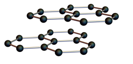
This article focuses on bilayer honeycomb lattice system to illustrate the physics in a simple yet relevant setting. Specific to this system, a symmetry change of the lattice induced by non-linear phononics produces an IL-DMI which is absence in the equilibrium lattice structure. This IL-DMI produces a non-collinear ground state with canting and result in topological magnon bands for a certain range of parameters.
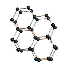
The honeycomb lattice model we study in this paper is motivated by a broad classes of materials with a layered honeycomb lattice structure. Common examples are the transition-metal dichalcogenides VX2(X=S, Se, and Te.), RuI3[63], RuCl3, and MoS2. For simplicity, we consider a honeycomb bilayer as a minimal model. Before we examine the effect that Raman modes can have on the DM interaction, we will study which vibrational modes are possible in a honeycomb bilayer. There are two most common stacking for a bilayer honeycomb lattice, referred to as AA and AB stacking (Bernard stacking). The point group for AA stacking is while the point group for AB stacking is . Both symmetries enforce the nearest neighbor interlayer DM interaction to be zero in equilibrium [2].
Both AA and AB stacked bilayer honeycomb lattices have twelve phonon modes since there are four atoms in the unit cell and three spatial directions in which atoms can move. In the case of AB stacking, the inversion center of the bilayer is the same as the nearest neighbor interlayer bond center, and thus all Raman modes are inversion symmetric at the bond center, forbidding the emergence of the nearest-neighbor IL-DMI. (See Appendix A for details.) Although, thermodynamically, for most materials, AB stacking is energetically more favorable [64], only in the case of AA stacking one can generate IL-DMI between the layers through non-linear phononics. In AA stacking, the system has point group symmetry where has the symmetry operations and represents inversion symmetry. The irreducible representations are , , , , , . The subscripts represent modes even (Raman) or odd (IR) under inversion symmetry. We now compute the irreducible representations of the vibrational modes in AA stacking, given by , where keeps track of the number of atoms that are mapped onto their same positions under point group operations, and is the vector representation whose basis functions are [53].
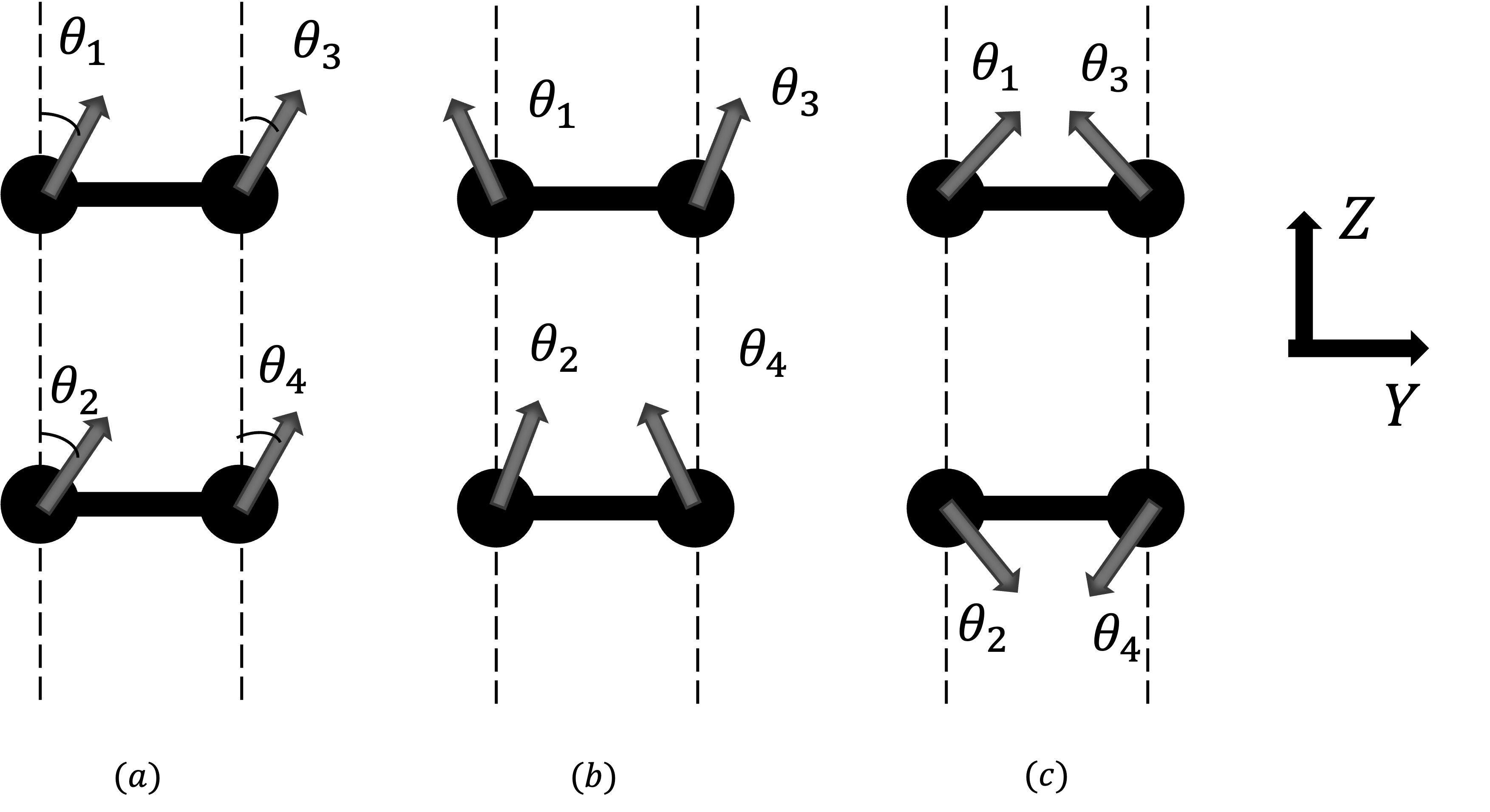
Three of these modes are acoustic: the mode and both modes, which correspond to center-of-mass (COM) motion in the directions. Besides these COM modes, there are modes that can break crucial symmetries enabling the existence of interlayer DM interactions. Among them, singly degenerate modes and exhibit out-of-plane motions while doubly degenerate and modes have in-plane motion only. In this article, we will focus on the modes since the mode is a shearing motion between layers, whose effect has been explored in an earlier work [62].
To determine the corresponding real space displacements (up to a unitary change of basis), we use the projection operator [53]
| (5) |
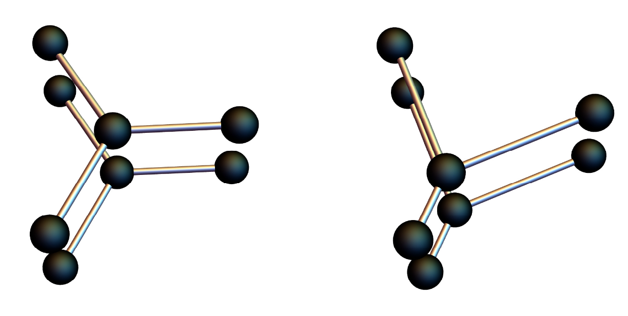
where is the irreducible matrix representation of the group element , is the order of the group, is the dimension of the irreducible representation, and is the representation of constructed by the permutation matrix and the O symmetry operations. The computed real space displacements of the mode are shown in Fig.2, which change the bond length in the -direction. The degenerate partner changes the bond length in the -direction.
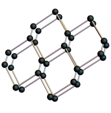
The modes break the 3-fold axis which allows an inter-layer DM interaction, with the symmetry requirement -plane, where appears in Eq.(1). The character table (from group theory) shows the mode has quadratic generating functions: and , which identifies it as a Raman mode. The mode has linear generating function identifying it is an IR mode.
By a group theory analysis [53], symmetry-allowed anharmonic coupling between the IR mode and the Raman mode can be written as,
| (6) |
where the “a” and “b” refer to orthogonal vibration modes, which could be taken as a linear combination of and -directional vibrations. The average positions of Raman modes when coupled to the IR modes with an external electric field are shifted as [57, 65],
| (7) | |||||
| (8) |
where and are the electric field components in the and -directions which couple to the electric dipole of the IR modes, and is the phase difference between the and -components. Detailed calculations are given in Radaelli [57].
From Eq.(7) and Eq.(8), it is evident that one can excite Raman modes in a specific direction through a choice of the electric field direction. In the Sec. II.3, we will see how these modes influence the intra-layer DM interaction and spin ground state. Note that in the usual experimental situation, most bilayer structures energetically favor AB stacking, but under pressure and with topological defects [66], one can still achieve AA stacking.
II.3 Nonzero DMI from a driven mode
The key observation is that if one excites the Raman mode in the -direction, the point group of the AA stacked bilayer effectively changes from to . Taking the time average of the Hamiltonian over a period of the Raman oscillation, the nonlinear phononics coupling effectively changes the lattice configuration, and allows a non-zero DM vector, , for nearest neighbor inter-layer exchange interactions. This is one of the central results of this work. The DMI originates from the breaking of inversion symmetry along the bond connecting nearest neighbors in the upper and lower layer of the AA stacked honeycomb lattices.
Considering the interlayer DM interaction, in the static case, it would be zero due to Moriya’s rules: it has both a 3-fold rotational axis along the bond and a mirror plane including the bond. Breaking of symmetry could lower the symmetry to only mirror symmetry, allowing a DMI perpendicular to the mirror plane. To linear order in the Raman mode displacement,
| (9) |
where is the distance separating the two layers, and is the strength of the spin-orbit coupling. The direction of is perpendicular to the -plane. An exact relation between the interlayer DM and phonon modes would need further detailed first principle calculations for a specific material. We are interested primarily in general considerations here.
In the following section, we will show that this light-induced IL-DMI can change the magnetic order of the ground state and can result in a gap opening for spin-wave excitations, i.e. the magnons, above the ground state, leading to a topological magnon band transition.
III Model Spin Hamiltonian
The above discussion on driven phonons depends only on lattice symmetry rather than an explicit spin Hamiltonian. To explore the consequences of the generation of an IL-DMI we choose a spin Hamiltonian with an easy-axis exchange interaction, where the intra-layer exchange interaction is ferromagnetic and the inter-layer exchange is chosen to be either ferromagnetic or anti-ferromagnetic to represent different possibilities for material realizations.
In the presence of the symmetry lowering from the shear mode described in the previous section, an IL-DMI and bond-dependent nearest-neighbor exchange interactions are induced. The effective light-driven spin Hamiltonian can be written as,
| (10) | |||||
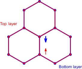
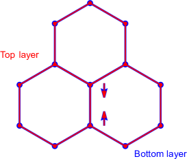
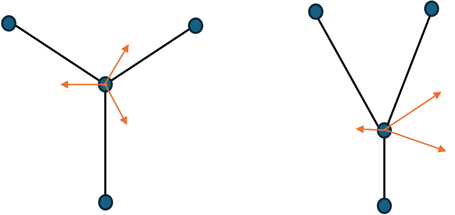
where is the top or bottom layer index, are site indices, and corresponds ferromagnetism within the plane. Here corresponds to the ferromagnetic coupling between layers, and antiferromagnetic coupling. We also include a second nearest-neighbor intralayer DMI that is generally allowed by the symmetry. As indicated in Fig.3, in the last term of Eq.(10) is perpendicular to the -plane. We choose which favors all spins pointing in the -direction for simplicity. In principle, all the exchange parameters can change when driving the system, but we focus on the IL-DMI term, .
To obtain a better sense of the scale of the exchange interactions for some representative materials, note that is about 0.004 and 0.06 in CrI3 and CrBr3, respectively [67]. The lowering of the symmetry via nonlinear phonics produces the new IL-DMI term which changes the symmetry of the magnetic ground state. The interlayer DM must be perpendicular to the -axis and parallel to the -plane, so IL-DMI takes the following form: . The sign of depends on material details and is related to the direction of the effective electric field contributing to the spin-orbit coupling [2].
Since the DMI, which originates from SOC, is usually one order of magnitude smaller than , we assume the DMI only contributes small canting to the original collinear ordering rather than producing spiral orders or other spin textures that enlarge the unit cell. The lowest-energy magnetic configuration can be calculated classically under the ansatz that the magnetic order does not enlarge the unit cell by minimizing the classical energy for different configurations of the magnetic moments. The lowest-energy configuration, when no external magnetic field is added, is illustrated in Fig. 3. The canting structure is coplanar when there is no external field. When the interlayer coupling is ferromagnetic (i.e., ), . For the AFM interlayer coupling case (i.e., ), . Applying an external magnetic field for directions not in the plane of the canting makes the spin stucture non-coplanar.
III.1 Magnon spectrum in the driven lattice
To compute the magnon spectrum we perform a Holstein-Primakoff transformation [68] in the non-interacting magnon limit which is the leading order in a expansion for fluctuations around the lowest-energy magnetic configuration, where is the magnitude of the spin. For the case of a non-collinear ground state, before expanding in the magnon basis, one needs to perform a local spin-rotation transformation so that the local -axis points along the direction of the spin in the classical ground state. To express the spin orientations resulting from the classical energy minimization, we use the standard cylindrical coordinate system,
| (11) |
In this way, we rewrite the spin Hamiltonian to a local basis such that we could perform the Holstein-Primakoff transformation on a local basis.
| (12) |
where and are the standard rotational matrices in three-dimensional space. The values of and are determined through classical energy minimization.
The spin component in the local coordinates are related to Holstein-Primakoff bosons as,
| (15) |
where are the Holstein-Primakoff bosons, and the sublattice bases should be thought of as carried implicitly. The canting induced from the IL-DMI breaks the spin symmetry of the collinear state down to , leading to the pairing of bosons. Therefore, one needs to introduce the Bogoliubov de Gennes (BdG) basis [69], . After a Fourier transformation to reciprocal space, the magnon Hamiltonian can be written in BdG form as,
| (16) |
In the absence of an external magnetic field, the groundstate satisfies and , the explicit form of the BdG Hamiltonian is
| (17) | ||||
where , and are matrices in particle-hole, layer, and sublattice subspaces respectively. The lattice basis vectors are chosen as , , and sublattice basis is , also , and , , are the three NN bonds , , , , are the three NNN bonds, , , .
In determining the magnon band structure and eigenstates, one must take into account the bosonic statistics of the magnons,
| (18) |
To diagonalize the magnon BdG Hamiltonian without changing the bosonic commutation relation, we use a para-unitary matrix [70], such that the BdG Hamiltonian can be diagonalized by the matrix as
| (19) |
with
| (20) |
to preserve the bosonic commutator.
Because of the particle-hole symmetry of the BdG basis, is the eigenenergy of the particle (hole) band. Since , we have
| (21) |
With this transformation, the eigenproblem of solving the BdG Hamiltonian can be reduced to solving the eigenproblem of the non-Hermitian Hamiltonian .
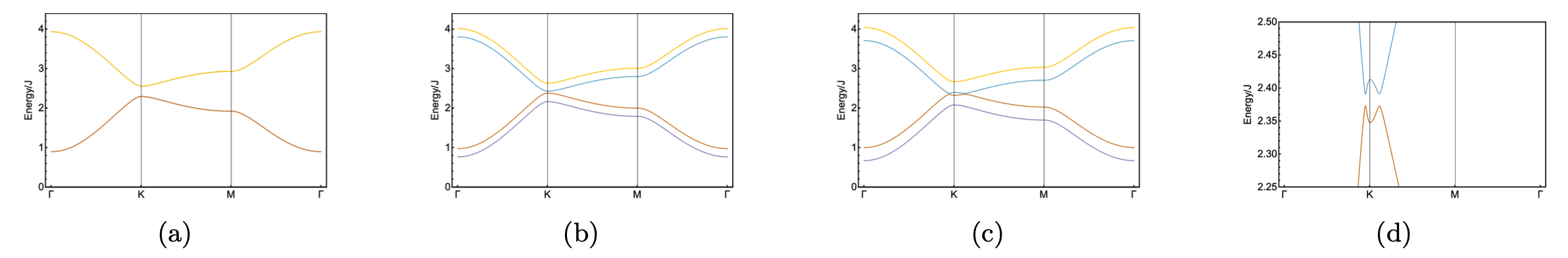
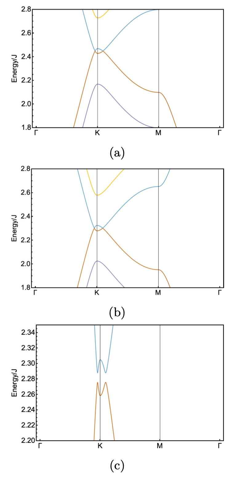
In Fig. 4, we show the magnon dispersion with and without the phonon-induced IL-DMI. In general, the phonon-induced IL-DMI favors a co-planar canted magnetic groundstate, yet either an external magnetic field (Fig. 4(b)) or the IL-DMI (Fig. 4 (a)) alone does not open up the gap between the middle two bands. However, a combination of both the IL-DMI and an external magnetic field favors a non-coplanar canting and opens a gap between the two middle bands (Fig. 4 (c)).
III.2 Magnon topology and band Chern number
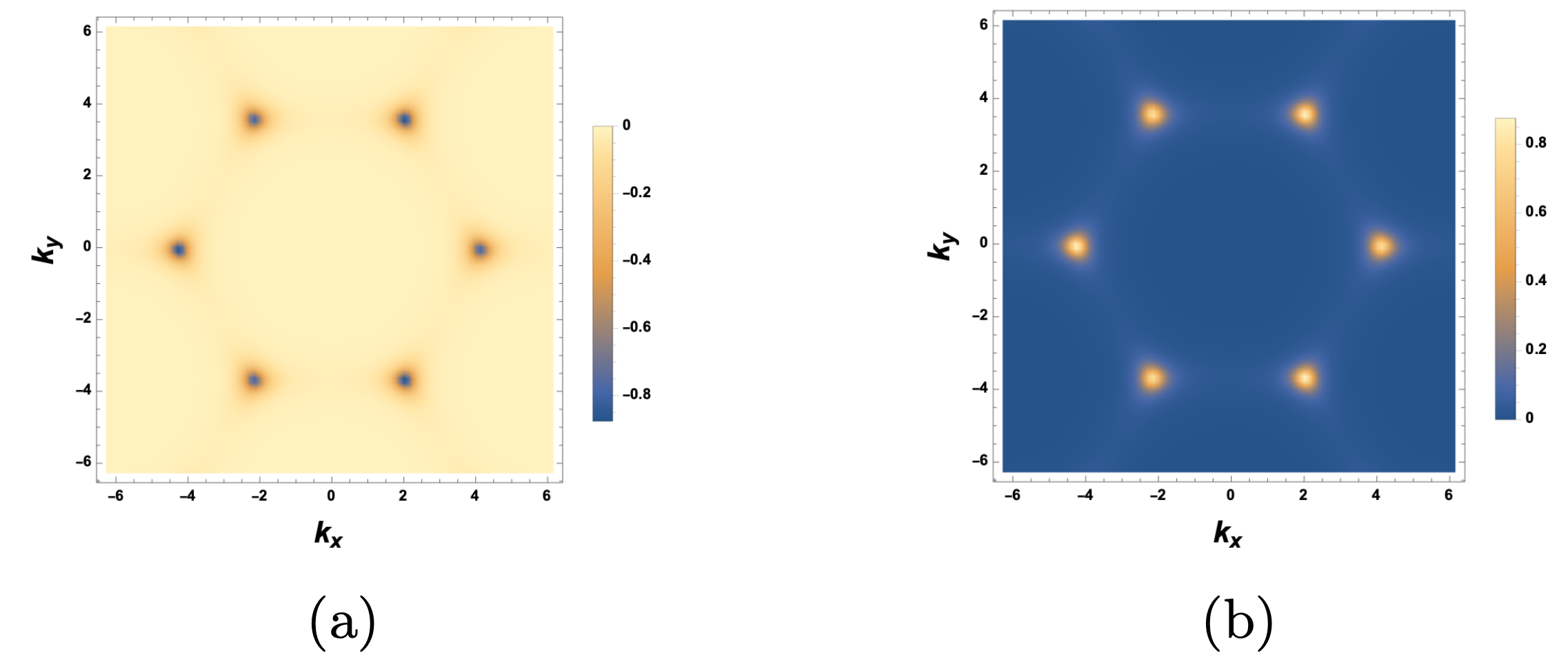
With this transformation the problem of solving the BdG Hamiltonian has been reduced to solving the eigenproblem of the non-Hermitian Hamiltonian . The positive eigenvalues are the physical magnon spectrum. The non-Hermiticity modifies the inner product in this symplectic vector space as which in turn modifies the definition of the magnon Berry connection and Berry curvature [70],
| (22) |
where is the eigenvector of with eigen-energy , for particle(hole) bands. And the berry curvature is given by
| (23) |
The numerical evaluation of the Berry curvature is done following Fukui’s method [71]. The integration of the Berry curvature over the first BZ is the Chern number,
| (24) |
a topological invariant of the magnon bands which can only change with gap closings and re-openings.
Because a gap opens with non-zero IL-DMI in the presence of a magnetic field, it is natural to investigate the topological properties through magnon band Chern numbers. The IL-DMI gives an extra tuning knob of the system’s properties that can be controlled with ultrafast precision using a laser drive. Some choices of Hamiltonian parameters with a gapped magnon spectrum and non-zero Chern numbers are listed in Table 1. The coexistence of IL-DMI and external B field is essential to gap out the middle two bands in the AFM and FM cases and enable a correct assignment of Chern number to each band.
Temperature-dependent thermal Hall measurements are one possible route to experimentally gain indirect access to the Chern numbers and Berry curvatures of topological magnon bands [72, 73, 74]. Because the population of the magnon bands depends on the temperature, the lowest-lying bands will determine the thermal transport properties [73]. However, since magnons are bosons, it is not possible to have completely “filled bands,” and therefore, a quantized thermal Hall response is not expected (as it would be for fermions that completely occupy some set of bands). While transport properties are not the focus of this paper, we note here that it is possible to partially infer information about the Berry curvature and Chern numbers from the thermal Hall response. While such “fast” (on the scale of nano or even picoseconds) transport experiments are extremely challenging, recent progress in electron transport shows that capabilities are rapidly advancing [75]. Finally, we remark that magnetically sensitive light experiments (e.g., through frequency-dependent light polarization rotation) could also be used to infer some properties of the magnon band structure.
| Hamiltonian Parameters | FM | FM | AFM |
|---|---|---|---|
| , | -1,-1,1,1 | -1,ND,ND,1 | degenerate |
| , | -1,-1,1,1, | -1,ND,ND,1 | 1, -1, -1, 1 |
| , | -1,-1,1,1, | -1, ND,ND,1 | degenerate |
| , | -1,-1,1,1, | -1,1,-1,1 | 1, -1, -1, 1 |
| , | -1,-1,1,1, | -1, 1,-1,1 | -1, 1, 1, -1 |
IV Conclusion and Outlook
In this work, we have theoretically studied a bilayer honeycomb lattice model subjected to a strong laser drive in resonance with infrared phonons. In this regime, phonon anharmonic couplings are relevant, and transient lattice distortions can be induced via cubic infrared-Raman phonon couplings. We further showed that the transiently distorted lattice possesses lower symmetry than an equilibrium lattice and that an interlayer Dyzaloshinkii-Moriya interaction is allowed. This is one of the central results of this work.
We then explored the resulting changes in the magnetic Hamiltonian, magnetic ground states, and excitations above the ground state. In particular, we found that the interlayer Dzyaloshinkii-Moriya interaction produces spin canting in the ground state which can endow the magnetic excitations (magnons) with topological properties. We explicitly computed the Berry curvature and Chern numbers of the magnon bands for selected parameters and demonstrated that topological transitions occur, such as when a static external magnetic field is applied.
For technological applications, it is beneficial to have control and tunability of material properties. We have discussed the advantages of using phonon-photon interactions to engineer magnetic systems (ultra-fast reversible control of the magnetic Hamiltonian). For example, because the energy scale of the phonon-photon interaction is smaller than the electron-photon one, and because the phonon energy scale is typically lower than the electronic energy scale, directly exciting phonons produces fewer undesirable heating effects in the system.
Our work serves as a proof of concept for the nonlinear phononics mechanism for modifying interesting magnetic phases and their excitations through the concrete protocol for inducing an interlayer Dyzaloshinkii-Moriya interaction in layered van der Waals materials. We hope this work will inspire further theoretical and experimental efforts in this direction.
Acknowledgements.
Z.L. is grateful to Michael Vogl and Luyan Yu for their helpful discussions and inspirational comments. Special thanks to Benjamin Wieder for his detailed guidance and discussions on symmetry, topology and everything condensed matter physics. This research was primarily supported by the National Science Foundation through the Center for Dynamics and Control of Materials: an NSF MR- SEC under Cooperative Agreement No. DMR-1720595 and NSF Grant No. DMR-2114825. G.A.F acknowledges additional support from the Alexander von Humboldt Foundation.References
- Dzyaloshinsky [1958] I. Dzyaloshinsky, A thermodynamic theory of “weak” ferromagnetism of antiferromagnetics, Journal of Physics and Chemistry of Solids 4, 241 (1958).
- Moriya [1960] T. Moriya, Anisotropic Superexchange Interaction and Weak Ferromagnetism, Physical Review 120, 91 (1960).
- Hellman et al. [2017] F. Hellman, A. Hoffmann, Y. Tserkovnyak, G. S. D. Beach, E. E. Fullerton, C. Leighton, A. H. MacDonald, D. C. Ralph, D. A. Arena, H. A. Dürr, P. Fischer, J. Grollier, J. P. Heremans, T. Jungwirth, A. V. Kimel, B. Koopmans, I. N. Krivorotov, S. J. May, A. K. Petford-Long, J. M. Rondinelli, N. Samarth, I. K. Schuller, A. N. Slavin, M. D. Stiles, O. Tchernyshyov, A. Thiaville, and B. L. Zink, Interface-induced phenomena in magnetism, Rev. Mod. Phys. 89, 025006 (2017).
- Kuepferling et al. [2023] M. Kuepferling, A. Casiraghi, G. Soares, G. Durin, F. Garcia-Sanchez, L. Chen, C. H. Back, C. H. Marrows, S. Tacchi, and G. Carlotti, Measuring interfacial dzyaloshinskii-moriya interaction in ultrathin magnetic films, Rev. Mod. Phys. 95, 015003 (2023).
- Huse and Elser [1988] D. A. Huse and V. Elser, Simple variational wave functions for two-dimensional heisenberg spin-½ antiferromagnets, Phys. Rev. Lett. 60, 2531 (1988).
- Bernu et al. [1992] B. Bernu, C. Lhuillier, and L. Pierre, Signature of néel order in exact spectra of quantum antiferromagnets on finite lattices, Phys. Rev. Lett. 69, 2590 (1992).
- Fert et al. [2017] A. Fert, N. Reyren, and V. Cros, Magnetic skyrmions: advances in physics and potential applications, Nature Reviews Materials 2, 10.1038/natrevmats.2017.31 (2017).
- Dieny et al. [2020] B. Dieny, I. L. Prejbeanu, K. Garello, P. Gambardella, P. Freitas, R. Lehndorff, W. Raberg, U. Ebels, S. O. Demokritov, J. Akerman, A. Deac, P. Pirro, C. Adelmann, A. Anane, A. V. Chumak, A. Hirohata, S. Mangin, S. O. Valenzuela, M. C. Onbaşlı, M. d’Aquino, G. Prenat, G. Finocchio, L. Lopez-Diaz, R. Chantrell, O. Chubykalo-Fesenko, and P. Bortolotti, Opportunities and challenges for spintronics in the microelectronics industry, Nature Electronics 3, 446 (2020).
- Marrows and Zeissler [2021] C. H. Marrows and K. Zeissler, Perspective on skyrmion spintronics, Applied Physics Letters 119, 250502 (2021), https://pubs.aip.org/aip/apl/article-pdf/doi/10.1063/5.0072735/14553914/250502_1_online.pdf .
- Fischer et al. [2020] P. Fischer, D. Sanz-Hernández, R. Streubel, and A. Fernández-Pacheco, Launching a new dimension with 3D magnetic nanostructures, APL Materials 8, 010701 (2020), https://pubs.aip.org/aip/apm/article-pdf/doi/10.1063/1.5134474/19798548/010701_1_1.5134474.pdf .
- Vedmedenko et al. [2019] E. Y. Vedmedenko, P. Riego, J. A. Arregi, and A. Berger, Interlayer dzyaloshinskii-moriya interactions, Phys. Rev. Lett. 122, 257202 (2019).
- Han et al. [2019] D.-S. Han, K. Lee, J.-P. Hanke, Y. Mokrousov, K.-W. Kim, W. Yoo, Y. L. W. van Hees, T.-W. Kim, R. Lavrijsen, C.-Y. You, H. J. M. Swagten, M.-H. Jung, and M. Kläui, Long-range chiral exchange interaction in synthetic antiferromagnets, Nature Materials 18, 703 (2019).
- Fernández-Pacheco et al. [2019] A. Fernández-Pacheco, E. Vedmedenko, F. Ummelen, R. Mansell, D. Petit, and R. P. Cowburn, Symmetry-breaking interlayer dzyaloshinskii–moriya interactions in synthetic antiferromagnets, Nature Materials 18, 679 (2019).
- Avci et al. [2021] C. O. Avci, C.-H. Lambert, G. Sala, and P. Gambardella, Chiral coupling between magnetic layers with orthogonal magnetization, Phys. Rev. Lett. 127, 167202 (2021).
- Guo et al. [2022] Y. Guo, J. Zhang, Q. Cui, R. Liu, Y. Ga, X. Zhan, H. Lyu, C. Hu, J. Li, J. Zhou, H. Wei, T. Zhu, H. Yang, and S. Wang, Effect of interlayer dzyaloshinskii-moriya interaction on spin structure in synthetic antiferromagnetic multilayers, Phys. Rev. B 105, 184405 (2022).
- Kammerbauer et al. [2023] F. Kammerbauer, W.-Y. Choi, F. Freimuth, K. Lee, R. Frömter, D.-S. Han, R. Lavrijsen, H. J. M. Swagten, Y. Mokrousov, and M. Kläui, Controlling the interlayer dzyaloshinskii–moriya interaction by electrical currents, Nano Letters 23, 7070 (2023), pMID: 37466639, https://doi.org/10.1021/acs.nanolett.3c01709 .
- Kent et al. [2021] N. Kent, N. Reynolds, D. Raftrey, I. T. G. Campbell, S. Virasawmy, S. Dhuey, R. V. Chopdekar, A. Hierro-Rodriguez, A. Sorrentino, E. Pereiro, S. Ferrer, F. Hellman, P. Sutcliffe, and P. Fischer, Creation and observation of hopfions in magnetic multilayer systems, Nature Communications 12, 1562 (2021).
- Basov et al. [2017] D. N. Basov, R. D. Averitt, and D. Hsieh, Towards properties on demand in quantum materials, Nature Materials 16, 1077 (2017).
- de la Torre et al. [2021] A. de la Torre, D. M. Kennes, M. Claassen, S. Gerber, J. W. McIver, and M. A. Sentef, Colloquium: Nonthermal pathways to ultrafast control in quantum materials, Rev. Mod. Phys. 93, 041002 (2021).
- Rodriguez-Vega et al. [2022a] M. Rodriguez-Vega, M. G. Vergniory, and G. A. Fiete, Quantum materials out of equilibrium, Physics Today 75, 42 (2022a).
- Bao et al. [2021] C. Bao, P. Tang, D. Sun, and S. Zhou, Light-induced emergent phenomena in 2D materials and topological materials, Nature Reviews Physics 2021 4:1 4, 33 (2021).
- Chang et al. [2013] C. Z. Chang, J. Zhang, X. Feng, J. Shen, Z. Zhang, M. Guo, K. Li, Y. Ou, P. Wei, L. L. Wang, Z. Q. Ji, Y. Feng, S. Ji, X. Chen, J. Jia, X. Dai, Z. Fang, S. C. Zhang, K. He, Y. Wang, L. Lu, X. C. Ma, and Q. K. Xue, Experimental observation of the quantum anomalous Hall effect in a magnetic topological Insulator, Science 340, 167 (2013).
- Merboldt et al. [2024] M. Merboldt, M. Schüler, D. Schmitt, J. P. Bange, W. Bennecke, K. Gadge, K. Pierz, H. W. Schumacher, D. Momeni, D. Steil, S. R. Manmana, M. A. Sentef, M. Reutzel, and S. Mathias, Observation of Floquet states in graphene, (2024).
- Nova et al. [2017] T. F. Nova, A. Cartella, A. Cantaluppi, M. Först, D. Bossini, R. V. Mikhaylovskiy, A. V. Kimel, R. Merlin, and A. Cavalleri, An effective magnetic field from optically driven phonons, Nature Physics 13, 132 (2017).
- Disa et al. [2020a] A. S. Disa, M. Fechner, T. F. Nova, B. Liu, M. Först, D. Prabhakaran, P. G. Radaelli, and A. Cavalleri, Polarizing an antiferromagnet by optical engineering of the crystal field, Nature Physics 16, 937 (2020a).
- Disa et al. [2023] A. S. Disa, J. Curtis, M. Fechner, A. Liu, A. von Hoegen, M. Först, T. F. Nova, P. Narang, A. Maljuk, A. V. Boris, B. Keimer, and A. Cavalleri, Photo-induced high-temperature ferromagnetism in ytio3, Nature 617, 73 (2023).
- Stupakiewicz et al. [2021] A. Stupakiewicz, C. S. Davies, K. Szerenos, D. Afanasiev, K. S. Rabinovich, A. V. Boris, A. Caviglia, A. V. Kimel, and A. Kirilyuk, Ultrafast phononic switching of magnetization, Nature Physics 17, 489 (2021).
- Davies et al. [2024] C. S. Davies, F. G. N. Fennema, A. Tsukamoto, I. Razdolski, A. V. Kimel, and A. Kirilyuk, Phononic switching of magnetization by the ultrafast barnett effect, Nature 10.1038/s41586-024-07200-x (2024).
- Mankowsky et al. [2017] R. Mankowsky, A. von Hoegen, M. Först, and A. Cavalleri, Ultrafast reversal of the ferroelectric polarization, Phys. Rev. Lett. 118, 197601 (2017).
- von Hoegen et al. [2018] A. von Hoegen, R. Mankowsky, M. Fechner, M. Först, and A. Cavalleri, Probing the interatomic potential of solids with strong-field nonlinear phononics, Nature 555, 79 (2018).
- Nova et al. [2019] T. F. Nova, A. S. Disa, M. Fechner, and A. Cavalleri, Metastable ferroelectricity in optically strained srtio¡sub¿3¡/sub¿, Science 364, 1075 (2019), https://www.science.org/doi/pdf/10.1126/science.aaw4911 .
- Henstridge et al. [2022a] M. Henstridge, M. Först, E. Rowe, M. Fechner, and A. Cavalleri, Nonlocal nonlinear phononics, Nature Physics 18, 457 (2022a).
- Li et al. [2019] X. Li, T. Qiu, J. Zhang, E. Baldini, J. Lu, A. M. Rappe, and K. A. Nelson, Terahertz field–induced ferroelectricity in quantum paraelectric srtio¡sub¿3¡/sub¿, Science 364, 1079 (2019), https://www.science.org/doi/pdf/10.1126/science.aaw4913 .
- Mitrano et al. [2016] M. Mitrano, A. Cantaluppi, D. Nicoletti, S. Kaiser, A. Perucchi, S. Lupi, P. Di Pietro, D. Pontiroli, M. Riccò, S. R. Clark, D. Jaksch, and A. Cavalleri, Possible light-induced superconductivity in K3C60 at high temperature, Nature 2016 530:7591 530, 461 (2016).
- Cantaluppi et al. [2018] A. Cantaluppi, M. Buzzi, G. Jotzu, D. Nicoletti, M. Mitrano, D. Pontiroli, M. Riccò, A. Perucchi, P. Di Pietro, and A. Cavalleri, Pressure tuning of light-induced superconductivity in k3c60, Nature Physics 14, 837 (2018).
- Budden et al. [2021] M. Budden, T. Gebert, M. Buzzi, G. Jotzu, E. Wang, T. Matsuyama, G. Meier, Y. Laplace, D. Pontiroli, M. Riccò, F. Schlawin, D. Jaksch, and A. Cavalleri, Evidence for metastable photo-induced superconductivity in k3c60, Nature Physics 17, 611 (2021).
- Rowe et al. [2023] E. Rowe, B. Yuan, M. Buzzi, G. Jotzu, Y. Zhu, M. Fechner, M. Först, B. Liu, D. Pontiroli, M. Riccò, and A. Cavalleri, Resonant enhancement of photo-induced superconductivity in k3c60, Nature Physics 19, 1821 (2023).
- Buzzi et al. [2020] M. Buzzi, D. Nicoletti, M. Fechner, N. Tancogne-Dejean, M. A. Sentef, A. Georges, T. Biesner, E. Uykur, M. Dressel, A. Henderson, T. Siegrist, J. A. Schlueter, K. Miyagawa, K. Kanoda, M.-S. Nam, A. Ardavan, J. Coulthard, J. Tindall, F. Schlawin, D. Jaksch, and A. Cavalleri, Photomolecular high-temperature superconductivity, Phys. Rev. X 10, 031028 (2020).
- Buzzi et al. [2021] M. Buzzi, D. Nicoletti, S. Fava, G. Jotzu, K. Miyagawa, K. Kanoda, A. Henderson, T. Siegrist, J. A. Schlueter, M.-S. Nam, A. Ardavan, and A. Cavalleri, Phase diagram for light-induced superconductivity in , Phys. Rev. Lett. 127, 197002 (2021).
- Fausti et al. [2011] D. Fausti, R. I. Tobey, N. Dean, S. Kaiser, A. Dienst, M. C. Hoffmann, S. Pyon, T. Takayama, H. Takagi, and A. Cavalleri, Light-induced superconductivity in a stripe-ordered cuprate, Science 331, 189 (2011).
- Nicoletti et al. [2014] D. Nicoletti, E. Casandruc, Y. Laplace, V. Khanna, C. R. Hunt, S. Kaiser, S. S. Dhesi, G. D. Gu, J. P. Hill, and A. Cavalleri, Optically induced superconductivity in striped by polarization-selective excitation in the near infrared, Phys. Rev. B 90, 100503 (2014).
- Kaiser et al. [2014] S. Kaiser, C. R. Hunt, D. Nicoletti, W. Hu, I. Gierz, H. Y. Liu, M. Le Tacon, T. Loew, D. Haug, B. Keimer, and A. Cavalleri, Optically induced coherent transport far above in underdoped , Phys. Rev. B 89, 184516 (2014).
- Hu et al. [2014] W. Hu, S. Kaiser, D. Nicoletti, C. R. Hunt, I. Gierz, M. C. Hoffmann, M. Le Tacon, T. Loew, B. Keimer, and A. Cavalleri, Optically enhanced coherent transport in yba2cu3o6.5 by ultrafast redistribution of interlayer coupling, Nature Materials 13, 705 (2014).
- von Hoegen et al. [2022] A. von Hoegen, M. Fechner, M. Först, N. Taherian, E. Rowe, A. Ribak, J. Porras, B. Keimer, M. Michael, E. Demler, and A. Cavalleri, Amplification of superconducting fluctuations in driven , Phys. Rev. X 12, 031008 (2022).
- Eckhardt et al. [2024] C. J. Eckhardt, S. Chattopadhyay, D. M. Kennes, E. A. Demler, M. A. Sentef, and M. H. Michael, Theory of resonantly enhanced photo-induced superconductivity, Nature Communications 2024 15:1 15, 1 (2024).
- Juraschek et al. [2021] D. M. Juraschek, T. c. v. Neuman, J. Flick, and P. Narang, Cavity control of nonlinear phononics, Phys. Rev. Res. 3, L032046 (2021).
- Dag and Rokaj [2023] C. B. Dag and V. Rokaj, Cavity Induced Topology in Graphene, (2023).
- Hübener et al. [2020] H. Hübener, U. De Giovannini, C. Schäfer, J. Andberger, M. Ruggenthaler, J. Faist, and A. Rubio, Engineering quantum materials with chiral optical cavities, Nature Materials 2020 20:4 20, 438 (2020).
- Curtis et al. [2019] J. B. Curtis, Z. M. Raines, A. A. Allocca, M. Hafezi, and V. M. Galitski, Cavity Quantum Eliashberg Enhancement of Superconductivity, Physical Review Letters 122, 167002 (2019).
- Losada et al. [2019] J. M. Losada, A. Brataas, and A. Qaiumzadeh, Ultrafast control of spin interactions in honeycomb antiferromagnetic insulators, Phys. Rev. B 100, 060410 (2019).
- Sato et al. [2016] M. Sato, S. Takayoshi, and T. Oka, Laser-driven multiferroics and ultrafast spin current generation, Phys. Rev. Lett. 117, 147202 (2016).
- Yambe and Hayami [2023] R. Yambe and S. Hayami, Symmetry analysis of light-induced magnetic interactions via floquet engineering, Phys. Rev. B 108, 064420 (2023).
- Dresselhaus et al. [2010] M. S. Dresselhaus, G. Dresselhaus, and A. A. Jorio, Group theory : application to the physics of condensed matter, , 582 (2010).
- Först et al. [2011] M. Först, C. Manzoni, S. Kaiser, Y. Tomioka, Y. Tokura, R. Merlin, and A. Cavalleri, Nonlinear phononics as an ultrafast route to lattice control, Nature Physics 7, 854–856 (2011).
- Born and Oppenheimer [1927] M. Born and R. Oppenheimer, Zur Quantentheorie der Molekeln, Annalen der Physik 389, 457 (1927).
- Subedi et al. [2014] A. Subedi, A. Cavalleri, and A. Georges, Theory of nonlinear phononics for coherent light control of solids, Physical Review B - Condensed Matter and Materials Physics 89, 220301 (2014).
- Radaelli [2018] P. G. Radaelli, Breaking symmetry with light: Ultrafast ferroelectricity and magnetism from three-phonon coupling, Physical Review B 97, 085145 (2018).
- Först et al. [2011] M. Först, C. Manzoni, S. Kaiser, Y. Tomioka, Y. Tokura, R. Merlin, and A. Cavalleri, Nonlinear phononics as an ultrafast route to lattice control, Nature Physics 2011 7:11 7, 854 (2011).
- Henstridge et al. [2022b] M. Henstridge, M. Först, E. Rowe, M. Fechner, and A. Cavalleri, Nonlocal nonlinear phononics, Nature Physics 2022 18:4 18, 457 (2022b).
- Disa et al. [2020b] A. S. Disa, M. Fechner, T. F. Nova, B. Liu, M. Först, D. Prabhakaran, P. G. Radaelli, and A. Cavalleri, Polarizing an antiferromagnet by optical engineering of the crystal field, Nature Physics 2020 16:9 16, 937 (2020b).
- Rodriguez-Vega et al. [2020] M. Rodriguez-Vega, Z. X. Lin, A. Leonardo, A. Ernst, G. Chaudhary, M. G. Vergniory, and G. A. Fiete, Phonon-mediated dimensional crossover in bilayer Cr I3, Physical Review B 102, 081117 (2020).
- Rodriguez-Vega et al. [2022b] M. Rodriguez-Vega, Z. X. Lin, A. Leonardo, A. Ernst, M. G. Vergniory, and G. A. Fiete, Light-Driven Topological and Magnetic Phase Transitions in Thin Layer Antiferromagnets, Journal of Physical Chemistry Letters 13, 4152 (2022b).
- Banerjee et al. [2018] A. Banerjee, P. Lampen-Kelley, J. Knolle, C. Balz, A. A. Aczel, B. Winn, Y. Liu, D. Pajerowski, J. Yan, C. A. Bridges, A. T. Savici, B. C. Chakoumakos, M. D. Lumsden, D. A. Tennant, R. Moessner, D. G. Mandrus, and S. E. Nagler, Excitations in the field-induced quantum spin liquid state of -RuCl3, npj Quantum Materials 2018 3:1 3, 1 (2018).
- Nguyen et al. [2020] V. L. Nguyen, D. L. Duong, S. H. Lee, J. Avila, G. Han, Y. M. Kim, M. C. Asensio, S. Y. Jeong, and Y. H. Lee, Layer-controlled single-crystalline graphene film with stacking order via Cu–Si alloy formation, Nature Nanotechnology 2020 15:10 15, 861 (2020).
- Juraschek et al. [2017] D. M. Juraschek, M. Fechner, and N. A. Spaldin, Ultrafast structure switching through nonlinear phononics, Phys. Rev. Lett. 118, 054101 (2017).
- Mcclarty [2021] P. A. Mcclarty, Topological Magnons: A Review, The Annual Review of Condensed Matter Physics is Annu. Rev. Condens. Matter Phys. 2022 13, 171 (2021).
- Owerre [2017] S. A. Owerre, Dirac Magnon Nodal Loops in Quasi-2D Quantum Magnets, Scientific Reports 2017 7:1 7, 1 (2017).
- Holstein and Primakoff [1940] T. Holstein and H. Primakoff, Field Dependence of the Intrinsic Domain Magnetization of a Ferromagnet, Physical Review 58, 1098 (1940).
- Bogoljubov [1958] N. N. Bogoljubov, On a new method in the theory of superconductivity, Il Nuovo Cimento Series 10 7, 794 (1958).
- Kondo et al. [2020] H. Kondo, Y. Akagi, and H. Katsura, Non-Hermiticity and topological invariants of magnon Bogoliubov–de Gennes systems, Progress of Theoretical and Experimental Physics 2020, 12 (2020).
- Fukui et al. [2005] T. Fukui, Y. Hatsugai, and H. Suzuki, Chern numbers in discretized Brillouin zone: Efficient method of computing (spin) Hall conductances, Journal of the Physical Society of Japan 74, 1674 (2005).
- Laurell and Fiete [2018] P. Laurell and G. A. Fiete, Magnon thermal hall effect in kagome antiferromagnets with dzyaloshinskii-moriya interactions, Phys. Rev. B 98, 094419 (2018).
- Laurell and Fiete [2017] P. Laurell and G. A. Fiete, Topological magnon bands and unconventional superconductivity in pyrochlore iridate thin films, Phys. Rev. Lett. 118, 177201 (2017).
- Ma and Fiete [2022] B. Ma and G. A. Fiete, Antiferromagnetic insulators with tunable magnon-polaron chern numbers induced by in-plane optical phonons, Phys. Rev. B 105, L100402 (2022).
- McIver et al. [2020] J. W. McIver, B. Schulte, F. U. Stein, T. Matsuyama, G. Jotzu, G. Meier, and A. Cavalleri, Light-induced anomalous hall effect in graphene, Nature Physics 16, 38 (2020).
- Cheong and Mostovoy [2007] S. W. Cheong and M. Mostovoy, Multiferroics: a magnetic twist for ferroelectricity, Nature Materials 2007 6:1 6, 13 (2007).
Appendix A Group Theory Analysis of Phonons
The lattice vibration modes can be determined by group theory from [53],
| (25) |
where counts the number of atoms within one unit cell which are mapped to themselves under spatial operations, and is the sum of the modes that transform as vectors.
The AB stacked honeycomb has a point group,
| (26) |
and the AA stacked honeycomb has a point group,
| (27) |
With this representation, one can determine the vibrational motion in real space [61, 62]. Both AA and AB stacked honeycomb lattices have twelve phonon modes since there are four atoms in the unit cell.
The modes describe shearing between layers [2]. The shearing modes break the -plane mirror symmetry and all two-fold symmetries, as well as the three-fold symmetry in the -direction normal to the plane of the bilayer. Therefore, a nearest neighbour DMI between the two closest interlayer atoms, one from the top layer and one from the bottom, is no longer forbidden. Symmetry requires that the DM vector be perpendicular to the plane.
A.0.1 Allowed phonon coupling in AA stacking
To see what kind of phonon interaction is allowed, we need to see if such interaction respect to crystal symmetry. For example in our case, we have , meaning that is an allowed interaction between phonons. More specifically, we have
| (28) |
where is a IR mode with irrep and is a Raman mode with irrep.
A.1 Real space displacement of phonon
The projection operator is constructed in the following way: [53]
| (29) |
where is the irreducible matrix representation of the group element , is the order of the group, is the dimension of the irreducible representation, and is the representation of constructed by the permutation matrix and the O symmetry operations. Once, we have this, the eigenmode for irreps can be calculated by finding the eigenvector of operator . In mode, the lattice has the following displacement vectors:
| (30) |
| (31) |
where , are the displacement vectors for sublattices in t(b) layer in the unit cell respectively, and are unit vectors in the and -directions.
A.2 Pictorial understanding of the 3-fold symmetry breaking
A 3-fold rotational symmetry guarantees a cancellation of all the contributions to the IL-DMI.
Appendix B Magnon Hamiltonian and the magnetic space group of the groundstate
B.1 Comments on magnetic exchange parameters
In the main text, we chose the nearest neighbor bonds to have the same exchange interaction . Although in the driven case this is only an approximation, the key physics remains the same.
B.2 Some comments on interlayer DM interaction

A simple model [76] that takes into account a third atom that breaks the inversion symmetry is illustrated in Fig.9, where a vector
| (32) |
is generated from inversion symmetry breaking where is a coefficient reflecting the strength of spin-orbit coupling, is a vector connecting atom 1 and atom 2, is the perpendicular to that points toward the third atom. In our situation, atom 1 and 2 are located in the opposite layer, and atom 3 would be some environmental atom.
B.3 Berry curvature and energy dispersion of magnon