pnasmathematics \leadauthorMosleh \significancestatementDeep decarbonization of transportation requires safe batteries with increased energy and power densities. All solid-state lithium metal batteries are a key technology promising all three of these. However, all solid-state lithium metal batteries can rarely cycle more than 100 times before the solid-solid interfaces significantly degrade. Here we propose a new morphogenesis framework to unite previous research in solid-state battery degradation and introduce a phenomenological model to accelerate design of persistent solid-solid interfaces. \authorcontributionsV.V. and L.M. conceived the research, all authors designed the research. S. M. and L.M. created the theoretical model, S.M. carried out the calculations, S. M. and E. A. wrote the first draft, all authors edited the paper. \authordeclarationV.V. is a technical consultant at QuantumScape Corporation. \correspondingauthor1To whom correspondence should be addressed. E-mail: lmahadev@g.harvard.edu
Controlling moving interfaces in solid state batteries
Abstract
Safe, all-solid-state lithium metal batteries enable high energy density applications, but suffer from instabilities during operation that lead to rough interfaces between the metal and electrolyte and subsequently cause void formation and dendrite growth that degrades performance and safety. Inspired by the morphogenetic control of thin lamina such as tree leaves that robustly grow into flat shapes — we propose a range of approaches to control lithium metal stripping and plating. To guide discovery of materials that will implement these feedback mechanisms, we develop a reduced order model that captures couplings between mechanics, interface growth, temperature, and electrochemical variables. We find that long-range feedback is required to achieve true interface stability, while approaches based on local feedback always eventually grow into rough interfaces. All together, our study provides the beginning of a practical framework for analyzing and designing stable electrochemical interfaces in terms of the mechanical properties and the physical chemistry that underlie their dynamics.
keywords:
energy storage morphogenesis Li metal batteries interface engineeringThis manuscript was compiled on
Lithium metal batteries promise higher energy density, safety, and charging rates, potentially enabling the widespread adoption of electric vehicles, trucks, and aircraft that rely on these for power (1, 2). A primary obstacle to robust functioning of these batteries is associated with instabilities at the interface between lithium and the solid electrolyte during charging/discharging cycles leading to uneven lithium stripping and deposition (3, 4), which leads to the formation of interfacial voids and dendrites. These defects can short-circuit the battery and cause failure (5).
Quenching the instability at the solid-solid interface has been the major focus of solid-state battery research for some time (6). When this fails, voids form due to non-conformal contact between the solid-solid interface and grow from manufacturing inhomogeneities (7, 8) when lithium is stripped from the anode and are exacerbated by local current concentration at void edges (9). Throughout cycling, current density enhancement creates the conditions for filament formation, where narrow lithium deposits grow from the anode to the cathode creating internal shorts and ending the usable life of a battery (10). On the other hand, maintaining a flat interface between the lithium electrode and the solid electrolyte can go a long way in reducing the propensity for battery failure.
Elucidating the role of electrochemical stability on the cycle life of all solid state batteries made it possible to create a design space of solid electrolytes and additives (11), enabling improvements in processing such as ball milling to increase initial performance. However, enhancement in cycle life (12) did not automatically follow. Over the last decade, two approaches have been proposed to enhance battery stability and robustness, increasing stack pressure and adding artificial interfaces. On its own, stack pressure cannot stabilize lithium deposition (13) and in some cases, might make the instability more prone to dendrite formation (14). However, due to the compliance of lithium metal, external pressure increases contact and simultaneously alters the interfacial kinetics to modulate and sometimes enhance interface stability (15, 16). In contrast, creating artificial interfaces can either increase or decrease stability; using sputtered or vapor deposited layers of Aluminum or Germanium alloys increases wettability and decreases interfacial resistance (17, 18), while Silver-Carbon and Tungsten interfacial materials showed promising cyclability of solid-state batteries (19, 20). All together, it is clear that we need to consider a combination of global regulation using external stack pressure and local chemical modifications to quench interface instability by changing the chemical response to alter the stable operating regime of solid-state batteries.
Here, we suggest a framework to achieve stable interface motion inspired by the observations of tightly regulated growth of living systems, morphogenesis, such as leaves that can maintain their flat shapes using various feedback mechanisms (21, 22, 23, 24). The reproducible patterns seen in morphogenesis are associated with the coupling of mesoscopic biophysical processes to molecular genetics that together control the transport, deformation, and flows underlying growing structures (25, 26, 27). Just as bio-inspired closed-loop feedback mechanisms can stabilize form, we propose that stabilizing the interface between electrodes and electrolytes can prevent the formation of void and dendrites. Indeed, conceptualizing both electrochemical interface and biological growths as examples of morphogenesis allows insights to flow between the two domains and provides a unique vantage point from which to think about regulating electrochemical interfaces — since their biological counter parts have evolved over millions of years to regulate shape with functional correlates that are subject to natural selection.
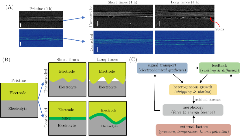
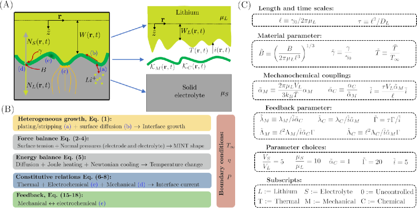
To describe the characteristics of battery cycling and the formation of instabilities, we study the dynamics of anode-electrolyte interface as shown in Fig. 1 B. The as-assembled flat interface begins to deform as instabilities grow during Lithium plating/deposition, while maintaining full contact for a period of time. At high enough current densities (or long enough time), the incompatibility between the flat electrolyte and the potentially curved surface of Lithium metal (due to inhomogeneous deposition) can cause delamination and void formation at anode-electrolyte interface (Fig. 1 B). As voids form, current localization accelerates plating in the contacted region and causes filaments to grow and become unstable (9). To prevent void and filament growth, we consider the role of adding a thin interfacial material at the electrode-electrolyte interface that implements closed-loop feedback by coupling non-flat morphology to Lithium deposition/stripping. The added morphogenic interface (MINT) material, shown in green in Fig. 1 B, could, under the right conditions, prevents contact loss and filament growth by implementing feedback between morphology and growth, which reduces the amplitude and increases the wavelength — maintaining a smoother and nearly flat interface — of interface undulations. To understand the conditions under which this might be feasible, we first turn to a theoretical framework and determine a stability diagram for the dynamics of the MINT, and then consider different practial options for its implementation.
Model for morphogenic interface dynamics
We assume that initially the electrode, electrolyte, and MINT are in full contact and the interface is nearly flat and coinciding with a horizontal plane characterized by coordinates and with a normal in the direction . The dynamic shape of the interface which varies during lithium stripping and plating is assumed to be given by (Fig. 2), and is analogous to the rest configuration of a spring when completely unloaded. We assume a thin MINT layer, whose thickness is smaller than the wavelength of interface displacements controlling void formation (m), and describe its mechanical behavior as a thin elastic shell with rest curvature (which we will see later is a geometric field subject to feedback control in an engineered setting and can serve to stabilize the interface mechanically), bending rigidity , and an effective surface tension for the combined electrode-MINT-electrolyte interface .
The combined effects of electrokinetics associated with plating and stripping and the presence of the solid (elastic) electrolytes on either side of the interface causes it deform and move. Since elastic forces equilibrate much faster compared with deposition and diffusion timescales, the shape of the combined interface is determine by solving the equilibrium force balance equations — that incorporates the effect of surface tension, MINT bending forces, and electrode-electrolyte normal indentation forces, denoted as and — at each time step. Mechanical forces and geometry of the combined interface will then modify the current density through mechanical and electrochemical feedback. In addition, current variation along the interface will lead to temperature variations , which in turn modify the kinetics of deposition. For a complete list of variable and parameter definitions see Fig. 2 and SI table S1.
Heterogeneous growth kinetics of the Lithium interface
Plating or stripping of the lithium surface, is dictated by the imbalance in the current density and spatial diffusion, leading to an equation of motion for the interface given by
| (1) |
where is the atomic volume of lithium, and the first term updates the shape of the lithium interface due to plating () or stripping () and the second term represents self (surface) diffusion of lithium with diffusivity .
Mechanical force balance
When due to variations in the current density, its contact with the flat solid electrolyte (Fig. 2) leads to mechanical forces that satisfy the following normal force balance equation(29):
| (2) |
where the first term is due to MINT bending relative to its rest natural curvature , the second is due to surface tension, and the last two terms are the normal pressures imposed by the electrode (subscript L) and electrolyte (subscript S) on the interface material that, for elastic substrates are given by the non-local terms associated with the Boussinesq-Cerruti solutions for the response of a half-space to surface forces (30)
| (3) |
| (4) |
where are the elastic moduli of the electrode and electrolyte materials and due to inhomogeneous deposition described by (1).
Energy balance
Since the interface dynamics are associated with heating which change the current, we need to consider how the temperature of the system changes as a function of joule heating and diffusion, leading to an equation for the system temperature given by
| (5) |
where is the thermal diffusion coefficient parallel to the interface, is the current through the interface with being a prescribed surface over-potential (with units of energy), and is the effective heat capacity (per unit area of the interface), and is the time-scale for thermal dissipation away from the interface to the bulk (which is assumed to be at temperature ).
Constitutive relations
Equations (1-5) describe the effect of current on interface morphological, mechanical, and thermal properties, which will in turn modify the current. To characterize the current density, we use a modified Butler-Volmer equation that accounts for the effect of mechanical forces (31) and electrochemical transport (32), so that we can write
| (6) |
where and are dimensionless constants, is the mechanical and is the chemical overpotential, and is the usual Boltzmann factor. Furthermore, is the unperturbed (flat interface) current density, which follows from the Butler-Volmer equation (33), with being the exchange current density and assuming a charge transfer coefficient of .
The mechanical overpotential (34, 35) is given by
| (7) |
where , and are the changes in pressure, relative to the flat state, in the electrode and electrolyte near the interface, and is the molar volume of lithium ions in the electrolyte. The electrochemical overpotential describes how chemical gradients and electric fields — and therefore current through Fick’s and Ohm’s laws — are modified due to interface curvature, which is described by the following equation [see Ref. (32) and SI for a derivation of these effects to linear order in interface curvature ]:
| (8) |
where , which has units of inverse length, and describes the position dependent interfacial conductivity of the electrode-MINT-electrolyte interface (which has thickness ), and is subject to feedback control using the MINT layer to potentially stabilize the interface. We note that the functional form of the electrochemical potential given by (8) and the mechanical overpotential given by Eqs. (3 - 4, 7) both have a nonlocal dependence on interface curvature. This completes the formulation of the governing equations for the thermo-electro-mechanical fields given by Eq. [1,2,5] subject to the closure relations [3-4,6-8].
Boundary and initial conditions
Dimensional analysis
Before we determine how mechanical properties and feedback mechanisms may control interface stability, we first consider the uncontrolled case, i.e. with vanishing rest curvature and conductance of the MINT, defined by the absence of the MINT layer and temperature variations:
| (10) |
where is the surface tension between the electrode and electrolyte and is the surface diffusivity of lithium in the absence of the MINT layer. This allows us to use dimensional analysis to characterize the parameters in the problem, as depicted in Fig. 1 C. Using the surface tension between the electrode and electrolyte and the lithium rigidity , we obtain the length scale . Using this length scale and the lithium (surface) diffusivity , we have the time scale . While the parameters and , which give the strength of the electrochemical and mechanochemical couplings respectively, are dimensionless, we defined the normalized constants and (see Fig. 1 C) that contain the parameter combinations appearing in subsequent calculations. To normalize the average current density , which appears in (6), we use the length and time scales defined above to obtain a velocity and the reciprocal of the molar volume of lithium to define a density, giving the normalized current (see Fig. 1 C). In addition, we also normalized the material parameters using their reference values in (10) to get the normalized bending rigidity of the MINT , the normalized surface tension , and normalized temperature (see Fig. 1 C).
Stability of morphogenic interface
Rather than solve equations (1-9) for specific initial and boundary conditions, here we consider the stability of an initially uniform interface, which is described by a constant current density (bar represents average quantities), temperature , and displacement . Expanding these four fields to linear order around this homogeneous base state, we carry out a linear stability analysis in terms of the spatial Fourier transform, which for a quantity is defined as . For each wavenumber , we calculate the growth rate of the interface, which grows according to
| (11) |
This allows us to determine the wavenumber with the maximum value of the growth rate ; a change in the sign of will characterize the transition from a stable to an unstable interface as a function of the parameters in the problem. We denote the maximum growth rate and corresponding wavenumber of the uncontrolled interface as
| (12) |
which will serve as reference values for comparison as the parameters of the systems are changed from those given in (10).
Uncontrolled Charging / Discharging
To obtain the growth rates in the following analysis (see SI for more details including for the controlled case), we first use (2), Fourier transformed as given in the SI, to solve for in terms of , using the expressions of the normal forces Eqs. (3-4). Then, using the expressions for the mechanical and electrochemical overpotentials, given in Eqs. (7-8), the current can be eliminated in terms of using (6). The results for and in (1) are then used to obtain a first order differential equation in time, from which we can read off the (wavelength-dependent) growth rate defined in (11).
Using the normalized average current (see Fig. 2 C), the ratio of molar volumes , ratio of elastic moduli , and the length scale , the normalized wavenumber , and time scale , we write the growth rate in the uncontrolled case as (see SI-S2 for details of the calculation)
| (13) |
Since typically (36), the growth rate given in (13) is always positive for small wavenumbers (long wavelengths) and will grow with the applied current according to:
| (14) |
Thus, this system is unstable for any value of current, due to two sources of instability: One mechanical () and the other electrochemical (). The mechanical instability results since negatively curved regions of the interface —corresponding to a lithium bumps growing into the electrolyte — lead to increased pressure near the interface which in turn drive more lithium ions towards the lithium metal when , amplifying the growth of the lithium into the electrolyte (36). The electrochemical instability happens due to the coupling of the curvature to current through (8), which can be understood intuitively since a lithium bump (negative interface curvature) would lead to an amplification of the local electric fields, which in turn leads to an increase in current density that exacerbates the instability (32).
Feedback control to stabilize the MINT
We see that in the absence of any regulatory process, there is a tendency for the interface to become unstable to long wavelength fluctuations, where elastic effects To stabilize the dynamics of the electrochemical interface, we now consider the role of the morphogenic interface which can be engineered to explicitly modify the mechanical and chemical driving forces on the interface, via potential closed-loop feedback mechanisms. We model such effects through the dynamic response of the mechanical and chemical natural curvatures, and . Translation and rotation invariance (associated with the assumption that the MINT is so thin as to be not affected by the battery size and shape) imply that and can depend on only through the interface curvature, which is given by to linear order. Thus, the most general forms of linear feedback can be written as:
| (15) |
| (16) |
where the kernels and describes the effect of interface curvature at position and time on the MINT mechanical rest curvature and conductance at a later time and position . To allow for the regulation of undulations with both small and long wavelengths, the kernels can in general include both local and long-range feedback in space-time — such feedback may be mediated by diffusing signals as in the case of growing leaves (37).
To study the effect of closed-loop feedback, we consider a diffusing signal that travels fast compared to the Lithium diffusive timescale so that a steady state approximation is valid. Then, we may write
| (17) | |||
| (18) |
where are constants defining the strength of spatio-temporally local feedback, while , are constants representing the strength of the non-local feedback. The function is the steady state solution of the diffusion equation with a point source at the origin and being a short distance cutoff, which approximates the effect of a diffusing agent — morphogen in the biological context (26, 38). The exponential function in time, with , is associated with the finite duration over which the signal (diffusing agent, or morphogen) is produced in response to nonzero interface curvature. With the feedback laws given in Eq. (17-18), the system now can be stabilized, even for very long wavelengths, with the growth rate
| (19) |
which is negative when the feedback parameter , defined in Fig. 1 C, is positive.
We note that the exact choice of and is not essential to achieve complete stability, as long as it is sufficiently long-range. In Fourier space, the long-range requirement can be stated precisely: Stability at requires that in this limit , with , and similarly for , with .
Decreasing growth rate with MINT material properties
Having established the uncontrolled growth as a reference case in (19), we consider how adding a morphogenic interface will modify the mechanical and chemical properties of the interface and stabilize the flat state — which we quantify as a reduction in the growth rate relative to . We considered the effect of three internal parameters (surface diffusion , surface tension , and MINT bending rigidity ), in addition to the role of external temperature and pressure.
Increasing the surface diffusion coefficient is thought to stabilize flat interfaces in solid state batteries (39) by redistributing lithium atoms from peaks to valleys in the interface. However due to the nonlocality of the sources of instability, Eqs. (3- 4) and (8), the instability always dominates for small wavenumbers, . In fact, as shown in SI Fig. S3, the slope of at is unchanged from its value in the uncontrolled case, which is given in (19). However, increasing decreases the maximum growth rate (SI Fig. S3 B).
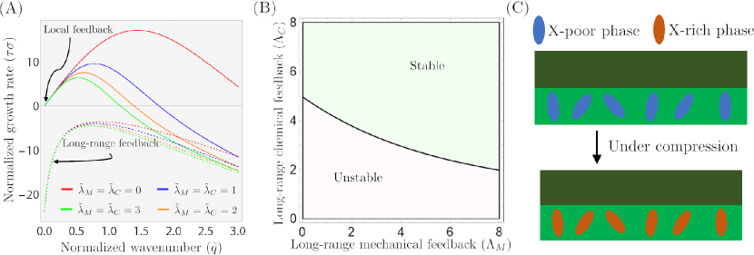
As shown in Fig. 3 A, (see also SI Fig. S3 C-D), increasing MINT rigidity and surface tension tends to decrease by providing mechanical support, which reduces the pressure variations across the interface that lead to the mechanochemical instability described in the previous section. Just as in the case of surface diffusion, these mechanical stabilizing factors act locally, as given in (2), and therefore do not modify the behavior of . These results support the use of adding rigid interlayers such as Al2O3 and modulating impurities in the solid electrolyte to increase the net surface tension, while still maintaining wetting of lithium onto the electrolyte as described in (40).
Since temperature affects interfacial resistance and other properties of the interface, the dynamics of heat flow may influence interface stability. Increasing temperature due to high applied current can lead to self-healing of lithium dendrites (41). In addition, we consider here the role of local temperature increases due to current hot spots in suppressing interface undulations. Our analysis (see SI text and SI Fig. S3) shows that the stabilizing effect of temperature is more pronounced for slow thermal diffusion , long cooling timescale over which heat escapes from the interface, and small volumetric heat capacity that amplifies temperature increase for the same amount of applied current density.
Lastly, to leading order in our analysis, pressure does not affect the growth rate since (7) only depends on the changes in pressure relative to the flat state (34, 35, 31, 36). However it is expected that pressure will increase stability of an interface due to higher order effects, such as plastic deformation (16, 8), which are not accounted for in our linear analysis.
Discussion
Inspired by regulated morphogenesis in biological systems, we have explored how to create self-regulating electrochemical interfaces (MINTs) with feedback control mechanisms that sense deviations from and restore a flat interface morphology. Since the sources of interface instability lead to long wavelength instabilities in the uncontrolled case, it is not surprising that only long-range feedback can truly lead to a stable interface with negative growth rate (Fig. 3 A-B).
Closed-loop feedback requires MINT materials that are capable of sensing the state of the interface (morphology, stress, concentrations, etc.,) and modifying its properties (e.g., conductivity, swelling, etc.,) accordingly. One such mechanism for sensing interface morphology is through inclusions inside the MINT is (shown in Fig. 3 C) that undergo a diffusive phase transition into an X-rich phase (e.g. X=sodium for example) when subjected to compression. By placing the inclusions on the side of the MINT closer to the electrode, they will transition to the X-rich phase only for when the interface curvature is negative (which results from a lithium bump pushing into the electrolyte), thus effectively sensing morphology. Mechanical actuation can be realized by coupling the amount of swelling (which determines the MINT natural curvature ) to the concentration of X (morphogen) signal outside the inclusions. Another possibility is using electrochemical feedback which can be realized by coupling the conductivity of the MINT to the amount of X, for example, sodium may reduce deposition by occupying sites important for lithium diffusion. Lastly, the long-range nature of the feedback can be accomplished through diffusion of X through the MINT, with the inclusions functioning either as sources or sinks depending on the direction of the phase transition (to or from the X-rich phase).
Overall, our study provides a benchmark for future studies of self-regulating MINTs, and our predictive model might help guide the discovery of promising materials that stabilize electrochemical chemical interfaces for energy intensive applications.
This work was supported by the Defense Advanced Research Project Agency (DARPA) under contract no. HR00112220032. The results contained herein are those of the authors and should not be interpreted as necessarily representing the official policies or endorsements, either expressed or implied, of DARPA, or the U.S. Government.
References
- Albertus et al. (2021) Paul Albertus, Venkataramani Anandan, Chunmei Ban, Nitash Balsara, Ilias Belharouak, Josh Buettner-Garrett, Zonghai Chen, Claus Daniel, Marca Doeff, Nancy J Dudney, et al. Challenges for and pathways toward li-metal-based all-solid-state batteries, 2021.
- Pasta et al. (2020) Mauro Pasta, David Armstrong, Zachary L Brown, Junfu Bu, Martin R Castell, Peiyu Chen, Alan Cocks, Serena A Corr, Edmund J Cussen, Ed Darnbrough, et al. 2020 roadmap on solid-state batteries. Journal of Physics: Energy, 2(3):032008, 2020.
- Lu et al. (2022) Yang Lu, Chen-Zi Zhao, Jiang-Kui Hu, Shuo Sun, Hong Yuan, Zhong-Heng Fu, Xiang Chen, Jia-Qi Huang, Minggao Ouyang, and Qiang Zhang. The void formation behaviors in working solid-state li metal batteries. Science Advances, 8(45):eadd0510, 2022.
- Cao et al. (2020) Daxian Cao, Xiao Sun, Qiang Li, Avi Natan, Pengyang Xiang, and Hongli Zhu. Lithium dendrite in all-solid-state batteries: growth mechanisms, suppression strategies, and characterizations. Matter, 3(1):57–94, 2020.
- Liu et al. (2022) Jia Liu, Hong Yuan, He Liu, Chen-Zi Zhao, Yang Lu, Xin-Bing Cheng, Jia-Qi Huang, and Qiang Zhang. Unlocking the failure mechanism of solid state lithium metal batteries. Advanced Energy Materials, 12(4):2100748, 2022.
- Boaretto et al. (2021) Nicola Boaretto, Iñigo Garbayo, Sona Valiyaveettil-SobhanRaj, Amaia Quintela, Chunmei Li, Montse Casas-Cabanas, and Frederic Aguesse. Lithium solid-state batteries: State-of-the-art and challenges for materials, interfaces and processing. Journal of Power Sources, 502:229919, August 2021. ISSN 0378-7753. 10.1016/j.jpowsour.2021.229919.
- Ishikawa et al. (2017) Kohei Ishikawa, Yasumasa Ito, Shunta Harada, Miho Tagawa, and Toru Ujihara. Crystal Orientation Dependence of Precipitate Structure of Electrodeposited Li Metal on Cu Current Collectors. Crystal Growth & Design, 17(5):2379–2385, May 2017. ISSN 1528-7483. 10.1021/acs.cgd.6b01710.
- Shishvan et al. (2021) Siamak S Shishvan, Norman A Fleck, and Vikram S Deshpande. The initiation of void growth during stripping of li electrodes in solid electrolyte cells. Journal of Power Sources, 488:229437, 2021.
- Eckhardt et al. (2022) Janis K. Eckhardt, Till Fuchs, Simon Burkhardt, Peter J. Klar, Jürgen Janek, and Christian Heiliger. 3D Impedance Modeling of Metal Anodes in Solid-State Batteries–Incompatibility of Pore Formation and Constriction Effect in Physical-Based 1D Circuit Models. ACS Applied Materials & Interfaces, 14(37):42757–42769, September 2022. ISSN 1944-8244, 1944-8252. 10.1021/acsami.2c12991.
- Bucci et al. (2017) Giovanna Bucci, Tushar Swamy, Yet-Ming Chiang, and W Craig Carter. Modeling of internal mechanical failure of all-solid-state batteries during electrochemical cycling, and implications for battery design. Journal of Materials Chemistry A, 5(36):19422–19430, 2017.
- Xu et al. (2018) R. C. Xu, X. H. Xia, S. Z. Zhang, D. Xie, X. L. Wang, and J. P. Tu. Interfacial challenges and progress for inorganic all-solid-state lithium batteries. Electrochimica Acta, 284:177–187, September 2018. ISSN 0013-4686. 10.1016/j.electacta.2018.07.191.
- Shin et al. (2014) Bum Ryong Shin, Young Jin Nam, Jin Wook Kim, Young-Gi Lee, and Yoon Seok Jung. Interfacial Architecture for Extra Li+ Storage in All-Solid-State Lithium Batteries. Scientific Reports, 4(1):5572, July 2014. ISSN 2045-2322. 10.1038/srep05572.
- Tu et al. (2020) Qingsong Tu, Luis Barroso-Luque, Tan Shi, and Gerbrand Ceder. Electrodeposition and Mechanical Stability at Lithium-Solid Electrolyte Interface during Plating in Solid-State Batteries. Cell Reports Physical Science, 1(7):100106, July 2020. ISSN 2666-3864. 10.1016/j.xcrp.2020.100106.
- Fincher et al. (2022) Cole D. Fincher, Christos E. Athanasiou, Colin Gilgenbach, Michael Wang, Brian W. Sheldon, W. Craig Carter, and Yet-Ming Chiang. Controlling dendrite propagation in solid-state batteries with engineered stress. Joule, 6(12):2794–2809, December 2022. ISSN 2542-4351. 10.1016/j.joule.2022.10.011.
- Ahmad and Viswanathan (2017a) Zeeshan Ahmad and Venkatasubramanian Viswanathan. Stability of Electrodeposition at Solid-Solid Interfaces and Implications for Metal Anodes. Physical Review Letters, 119(5):056003, August 2017a. 10.1103/PhysRevLett.119.056003.
- Barai et al. (2017) Pallab Barai, Kenneth Higa, and Venkat Srinivasan. Lithium dendrite growth mechanisms in polymer electrolytes and prevention strategies. Physical Chemistry Chemical Physics, 19(31):20493–20505, 2017.
- Fu et al. (2017) Kun (Kelvin) Fu, Yunhui Gong, Boyang Liu, Yizhou Zhu, Shaomao Xu, Yonggang Yao, Wei Luo, Chengwei Wang, Steven D. Lacey, Jiaqi Dai, Yanan Chen, Yifei Mo, Eric Wachsman, and Liangbing Hu. Toward garnet electrolyte–based Li metal batteries: An ultrathin, highly effective, artificial solid-state electrolyte/metallic Li interface. Science Advances, 3(4):e1601659, April 2017. 10.1126/sciadv.1601659.
- Luo et al. (2017) Wei Luo, Yunhui Gong, Yizhou Zhu, Yiju Li, Yonggang Yao, Ying Zhang, Kun (Kelvin) Fu, Glenn Pastel, Chuan-Fu Lin, Yifei Mo, Eric D. Wachsman, and Liangbing Hu. Reducing Interfacial Resistance between Garnet-Structured Solid-State Electrolyte and Li-Metal Anode by a Germanium Layer. Advanced Materials, 29(22):1606042, 2017. ISSN 1521-4095. 10.1002/adma.201606042.
- Lee et al. (2020) Yong-Gun Lee, Satoshi Fujiki, Changhoon Jung, Naoki Suzuki, Nobuyoshi Yashiro, Ryo Omoda, Dong-Su Ko, Tomoyuki Shiratsuchi, Toshinori Sugimoto, Saebom Ryu, Jun Hwan Ku, Taku Watanabe, Youngsin Park, Yuichi Aihara, Dongmin Im, and In Taek Han. High-energy long-cycling all-solid-state lithium metal batteries enabled by silver–carbon composite anodes. Nature Energy, 5(4):299–308, April 2020. ISSN 2058-7546. 10.1038/s41560-020-0575-z.
- Raj et al. (2022) Vikalp Raj, Victor Venturi, Varun R Kankanallu, Bibhatsu Kuiri, Venkatasubramanian Viswanathan, and Naga Phani B Aetukuri. Direct correlation between void formation and lithium dendrite growth in solid-state electrolytes with interlayers. Nature Materials, 21(9):1050–1056, 2022.
- Lempe et al. (2013) Janne Lempe, Jennifer Lachowiec, Alessandra M Sullivan, and Christine Queitsch. Molecular mechanisms of robustness in plants. Current opinion in plant biology, 16(1):62–69, 2013.
- Hamant and Moulia (2016) Olivier Hamant and Bruno Moulia. How do plants read their own shapes? New Phytologist, 212(2):333–337, 2016.
- Lenne et al. (2021) Pierre-François Lenne, Edwin Munro, Idse Heemskerk, Aryeh Warmflash, Laura Bocanegra-Moreno, Kasumi Kishi, Anna Kicheva, Yuchen Long, Antoine Fruleux, Arezki Boudaoud, et al. Roadmap for the multiscale coupling of biochemical and mechanical signals during development. Physical Biology, 18(4):041501, 2021.
- Moulia et al. (2021) Bruno Moulia, Stéphane Douady, and Olivier Hamant. Fluctuations shape plants through proprioception. Science, 372(6540), 2021.
- Thompson (1992) D’Arcy Wentworth Thompson. On Growth and Form. Canto. Cambridge University Press, 1992. 10.1017/CBO9781107325852.
- Turing (1952) Alan Mathison Turing. The chemical basis of morphogenesis. Philosophical Transactions of the Royal Society of London. Series B, Biological Sciences, 237(641):37–72, August 1952. 10.1098/rstb.1952.0012.
- Mahadevan (2020) L Mahadevan. Multicellular morphogenesis, in Physics Of Living Matter: Space, Time And Information, eds.; eds. Gross, D J, Sevrin, A, Shraiman, B; The-Proceedings Of The 27th Solvay Conference On Physics. World Scientific, 2020.
- Fu et al. (2020) Chengyin Fu, Victor Venturi, Jinsoo Kim, Zeeshan Ahmad, Andrew W Ells, Venkatasubramanian Viswanathan, and Brett A Helms. Universal chemomechanical design rules for solid-ion conductors to prevent dendrite formation in lithium metal batteries. Nature materials, 19(7):758–766, 2020.
- Landau et al. (1986) Lev Davidovich Landau, Evgenij M Lifšic, Evegnii Mikhailovich Lifshitz, Arnold Markovich Kosevich, and Lev Petrovich Pitaevskii. Theory of elasticity: volume 7, volume 7. Elsevier, 1986.
- Love (2013) Augustus Edward Hough Love. A treatise on the mathematical theory of elasticity. Cambridge university press, 2013.
- Ahmad and Viswanathan (2017b) Zeeshan Ahmad and Venkatasubramanian Viswanathan. Stability of electrodeposition at solid-solid interfaces and implications for metal anodes. Physical review letters, 119(5):056003, 2017b.
- Carmona and Albertus (2023) Eric A Carmona and Paul Albertus. Modeling how interface geometry and mechanical stress affect li metal/solid electrolyte current distributions. Journal of The Electrochemical Society, 170(2):020524, 2023.
- Bard et al. (2022) Allen J Bard, Larry R Faulkner, and Henry S White. Electrochemical methods: fundamentals and applications. John Wiley & Sons, 2022.
- Monroe and Newman (2004) Charles Monroe and John Newman. The effect of interfacial deformation on electrodeposition kinetics. Journal of The Electrochemical Society, 151(6):A880, 2004.
- Monroe and Newman (2005) Charles Monroe and John Newman. The impact of elastic deformation on deposition kinetics at lithium/polymer interfaces. Journal of The Electrochemical Society, 152(2):A396, 2005.
- Mistry and Mukherjee (2020) Aashutosh Mistry and Partha P Mukherjee. Molar volume mismatch: a malefactor for irregular metallic electrodeposition with solid electrolytes. Journal of the Electrochemical Society, 167(8):082510, 2020.
- al Mosleh and Mahadevan (2023) Salem al Mosleh and L. Mahadevan. How to grow a flat leaf. Phys. Rev. Lett., 131:098401, Aug 2023. 10.1103/PhysRevLett.131.098401. URL https://link.aps.org/doi/10.1103/PhysRevLett.131.098401.
- Wolpert (1969) Lewis Wolpert. Positional information and the spatial pattern of cellular differentiation. Journal of theoretical biology, 25(1):1–47, 1969.
- Jäckle et al. (2018) Markus Jäckle, Katharina Helmbrecht, Malte Smits, Daniel Stottmeister, and Axel Groß. Self-diffusion barriers: possible descriptors for dendrite growth in batteries? Energy & Environmental Science, 11(12):3400–3407, 2018.
- Sharafi et al. (2017) Asma Sharafi, Eric Kazyak, Andrew L Davis, Seungho Yu, Travis Thompson, Donald J Siegel, Neil P Dasgupta, and Jeff Sakamoto. Surface chemistry mechanism of ultra-low interfacial resistance in the solid-state electrolyte li7la3zr2o12. Chemistry of Materials, 29(18):7961–7968, 2017.
- Li et al. (2018) Lu Li, Swastik Basu, Yiping Wang, Zhizhong Chen, Prateek Hundekar, Baiwei Wang, Jian Shi, Yunfeng Shi, Shankar Narayanan, and Nikhil Koratkar. Self-heating–induced healing of lithium dendrites. Science, 359(6383):1513–1516, 2018.