Bound States in the Continuum in a Wire Medium
Abstract
We show that a slab of wire medium composed of thin parallel metallic wires can naturally support bound states in the continuum (BICs) formed in an unusual way. The revealed BICs appear due to the strong spatial dispersion making possible the propagation of longitudinal plasma-like waves and TEM polarized modes with a flat band. The symmetry-protected (at-) BICs are formed due to the polarization mismatch between the longitudinal plasma-like waves and transversal plane waves in the surrounding space, while the accidental (off-) BICs appear as a result of the Friedrich-Wintgen destructive interference between them. All revealed BICs can be well-described analytically without the use of the Bloch theorem within effective medium approximation when the wire medium behaves as homogeneous 1D anisotropic plasma with strong spatial dispersion.
Bound states in the continuum (BICs) are non-radiating resonances of open systems with a spectrum embedded in the continuum of the propagating waves of the surrounding space [1, 2, 3, 4]. BICs have attracted much attention in recent years in photonics because of their pronounced resonant properties, scalability to any frequency range, and compatibility with various photonic structures and materials [5, 6, 4]. BIC possesses a diverging radiative quality factor (Q-factor), strong field localization, and topological robustness with respect to the variation system’s parameters preserving its symmetry [7]. All these advantages make BICs very prospective for micro and nanolasers [8, 9, 10, 11], biosensors [12, 13], polaritonics [14, 15], and nonlinear photonic components [16, 17, 18].
The BICs are mostly studied in periodic photonic structures including both all-dielectric and plasmonic ones, where their origin is well-studied and understood [19, 2]. Periodicity makes the radiation possible only into the open diffraction channels that substantially simplifies observation BIC in practice, especially, in structures with subwavelength period where only two diffraction channels are open [7, 20, 21]. Another way to engineer BIC is the Friedrich-Wintgen scenario when the destructive interference of two resonant (leaky) states results in a complete cancellation of the radiation losses [22]. This mechanism can result in the appearance of BICs even in structures with continuous translation symmetry. Thus, destructive interference of the ordinary and extraordinary modes in planar anisotropic dielectric structures can result in complete suppression of radiation losses [23]. In acoustic structures, the same effect is achieved due to the interference between shear and longitudinal waves [24, 25, 26].
In this study, we unveil a novel scenario for Bound States in the Continuum (BIC) formation in photonic structures exhibiting strong spatial dispersion. This spatial dispersion enables the propagation of additional waves that can give rise to BICs. We illustrate this with the example of a wire medium composed of thin metallic wires, which can be effectively described as a homogeneous anisotropic medium with spatial dispersion [27]. Specifically, we demonstrate that both symmetry-protected and accidental BICs are formed in an extraordinary manner, with origins that differ significantly from those in dielectric structures. These BICs can be described within the framework of the effective medium approximation (EMA), whereas BICs in metasurfaces require consideration of the periodic potential and using the Bloch theorem. Another distinctive feature of the BICs identified in a wire medium is that accidental BICs are formed in a weak coupling regime, while according to common wisdom, the BICs are typically formed in a strong coupling regime, characterized by anticrossing between interacting states.
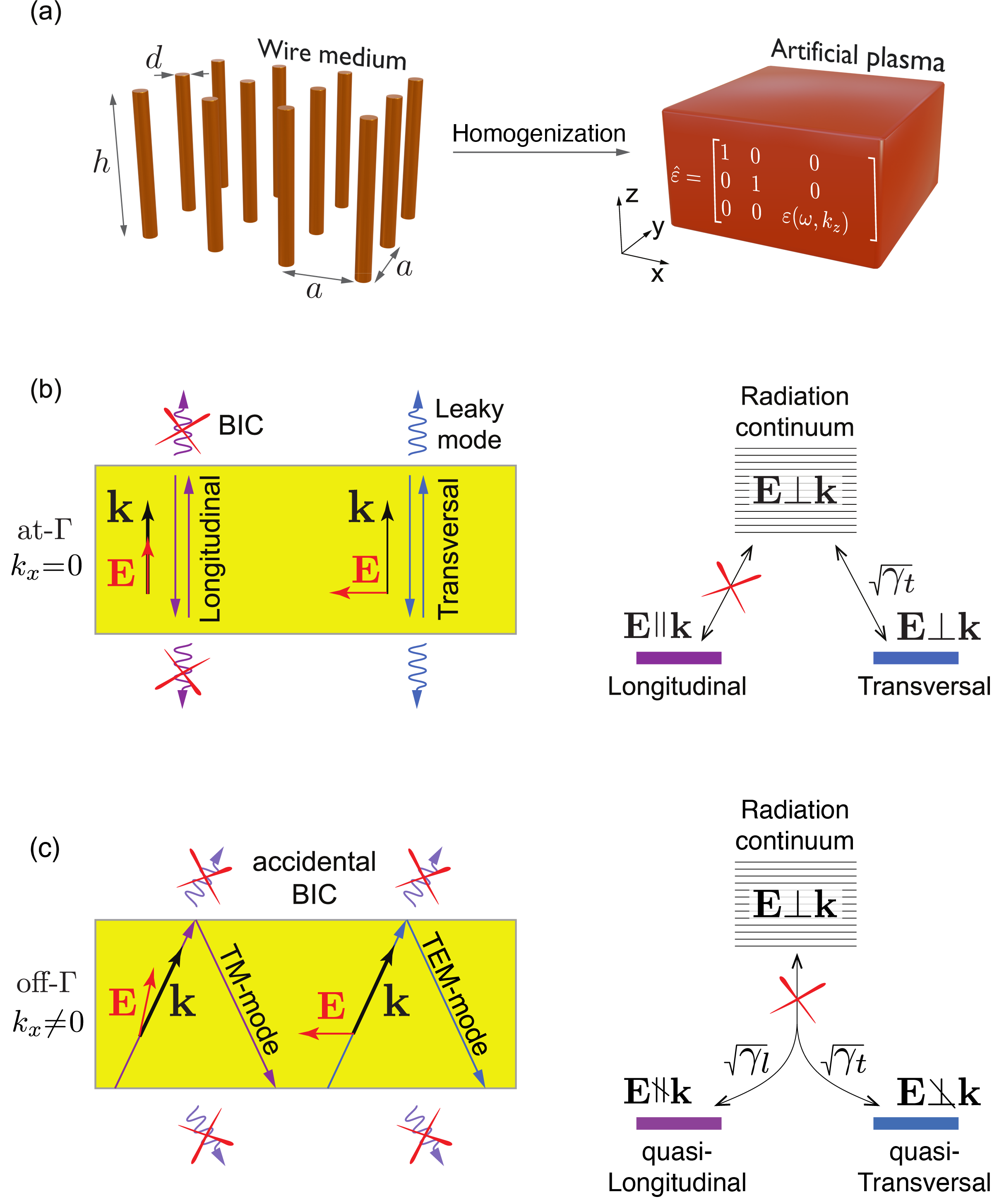
We consider a wire medium composed of finite-height thin metallic wires made of a perfect electric conductor (PEC) and arranged in a periodic pattern [see Fig. 1(a)]. Such media are well-studied in literature [27, 28, 29, 30, 31]. They have the ability to manipulate electromagnetic waves in a way that traditional materials cannot. Wire media can be designed to have a negative refractive index [32] or hyperbolic dispersion [33] and used for wave canalization [34], cloaking [35], and imaging with sub-wavelength resolution [36]. Within the EMA [27], the wire medium behaves as anisotropic 1D plasma with strong spatial dispersion that cannot be neglected even in the long-wave approximation when . Its dielectric tensor reads as [27]:
| (1) | |||
| (2) | |||
| (3) |
Here is the diameter of the PEC wires, is the lattice constant, is the plasma frequency of the wire medium.
The spectrum of a bulk wire medium consists of two types of modes: (i) plasma waves which are quasi-longitudinal and able to propagate only above the plasma frequency and (ii) TEM modes which can propagate at arbitrarily low frequencies. The dispersion of TEM modes do not depend on and and it is read as [28]. Therefore, the isofrequency surface is completely flat and energy propagates only along the wires. Finding the eigenmode spectrum in a slab of wire medium requires the introduction of additional boundary conditions [29, 37]. They can be found from the assumptions of zero current at the end-faces of the wires. The derivations of the dispersion equation and the reflection coefficient from the slab of wire medium are derived in the Supplemental Material [38].
A slab of a wire medium naturally supports two types of BICs that could be described within EMA without taking into account a periodic structure. At , the plasma modes are pure longitudinal () and the average on unit cell magnetic field tends to zero . Such a mode cannot couple to the transversal waves in the surrounding space due to the polarization mismatch and it turns into a symmetry-protected BIC [Fig. 1(b)]. Similar BICs appear in a slab of elastic material when the transverse (shear) acoustic wave does not couple to the longitudinal pressure waves in the surrounding fluid [24, 25, 26]. A similar mechanism of the BIC formation was recently studied in double-net metamaterials [39].
At or , both plasma and TEM waves are no longer independent. They mix forming leaky TM-modes which can be called quasi-plasma and leaky quasi-TEM modes depending on the dominant component. This mixture can be interpreted as interaction via the radiation continuum as shown in Fig. 1(c) but formally it is governed by the additional boundary conditions [29, 37]. At certain values of , the system can support the accidental BICs. They are formed when the radiative losses of the leaky mode are suppressed due to the destructive interference of plasma and TEM waves composing the mode (see the Supplemental Material for details [38]).
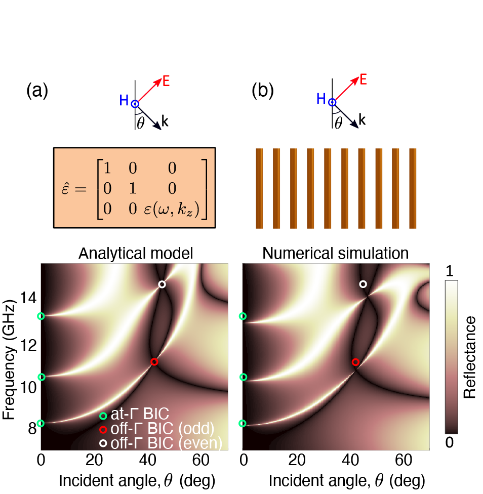
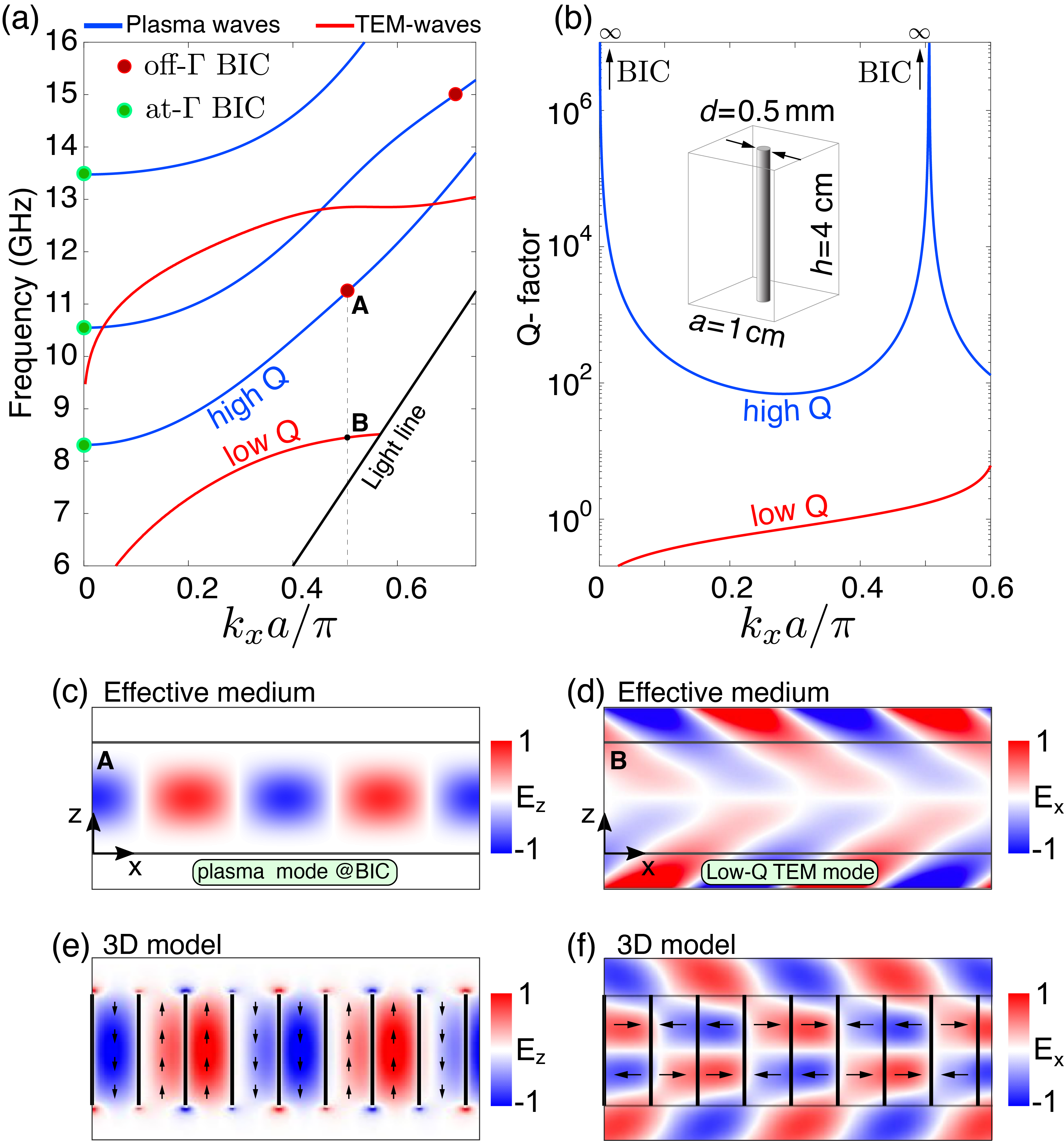
Figure 2(a) shows the eigenmode spectrum for the wire medium slab calculated within EMA (see Eq. S1). The dimension axes are introduced for reference. They correspond to the following parameters of a wire medium: mm; diameter of wires mm; length of wires mm [see Fig. 1(a)]. Such parameters give plasma frequency GHz. The red curves correspond to the quasi-TEM modes, while the blue curves correspond to the quasi-plasma modes discussed above. The divergence of the radiative Q-factor for and shown in Fig. 1(b) manifests the presence of symmetry-protected and accidental BICs. All accidental and symmetry-protected BICs are marked in Fig. 1(a) by red and green dots, respectively. It is worth mentioning that the accidental BICs in a wire medium appear in a weak coupling regime without characteristic avoid crossing in contrast to the majority of photonic systems where BICs appeared in the strong mode coupling regime [40].
The full wave 3D model and EMA match well and give the agreed values of the spectral and angular positions of BICs. However, the field distributions predicted from these two approaches are substantially distinct [see Figs. 2(c-f)]. In the full wave 3D model, BICs have no far-fields but have evanescent fields corresponding to the closed diffraction channels. Within the EMA, BICs have not both near- and far-fields. Thus, they become completely localized inside the slab. This is very unusual as even the waveguide modes have evanescent fields. The vanishing electric field outside the slab can be used as a feature for finding the angular and spectral positions of BICs (see the Supplemental Material [38]). The frequencies of the symmetry-protected BICs correspond to the Fabry-Perot resonance of the plasma wave across the slab:
| (4) |
Here is an integer. The frequencies of the accidental BICs correspond to the Fabry-Perot resonances of TEM mode, meanwhile is defined from the dispersion equation [38]:
| (5) |
Here and are integers of the same parity (odd/even).
Figure 3 shows the reflection spectra from the slab of wire medium calculated analytically within EMA [panel (a)] and using the full-wave numerical simulation [panel (b)]. The parameters of the medium are shown in the inset of Fig. 2(b). The incident waves are assumed to be p-polarized. Both methods are well agreed. Both symmetry-protected and accidental BICs manifest themselves as infinitely narrow peaks disappearing exactly at the BIC points. The circles in Figs. 3(a) and 3(b) indicate the spectral and angular positions of symmetry-protected and accidental BICs calculated with Eqs. (4) and (5). The slight deviations are explained by the framework of EMA. Thus, for thinner and longer wires the deviations are smaller.
BIC being a polarization vortex in the far- field, can be characterized by topological charge defined as the winding number of the polarization vortex which shows the number of counterclockwise rotations the electric field makes along the path in the k-space enclosed the BIC if going the counterclockwise direction [7, 20]. Therefore, BIC is robust against variations of any parameters preserving the symmetry of the system [41, 42, 43]. On the other hand, a BIC appears when the nodal line of the directivity diagram of the unit cell coincides with the direction of the open diffraction channel [44, 45]. The directivity diagram and topological charge of BIC can be well described by a few dominant multipoles of the mode which can be predicted from the group theory without direct calculations [7, 44, 46]. To gain deeper insight into the topological nature of BICs in a wire medium, we analyze their multipolar composition using the group theory [44].
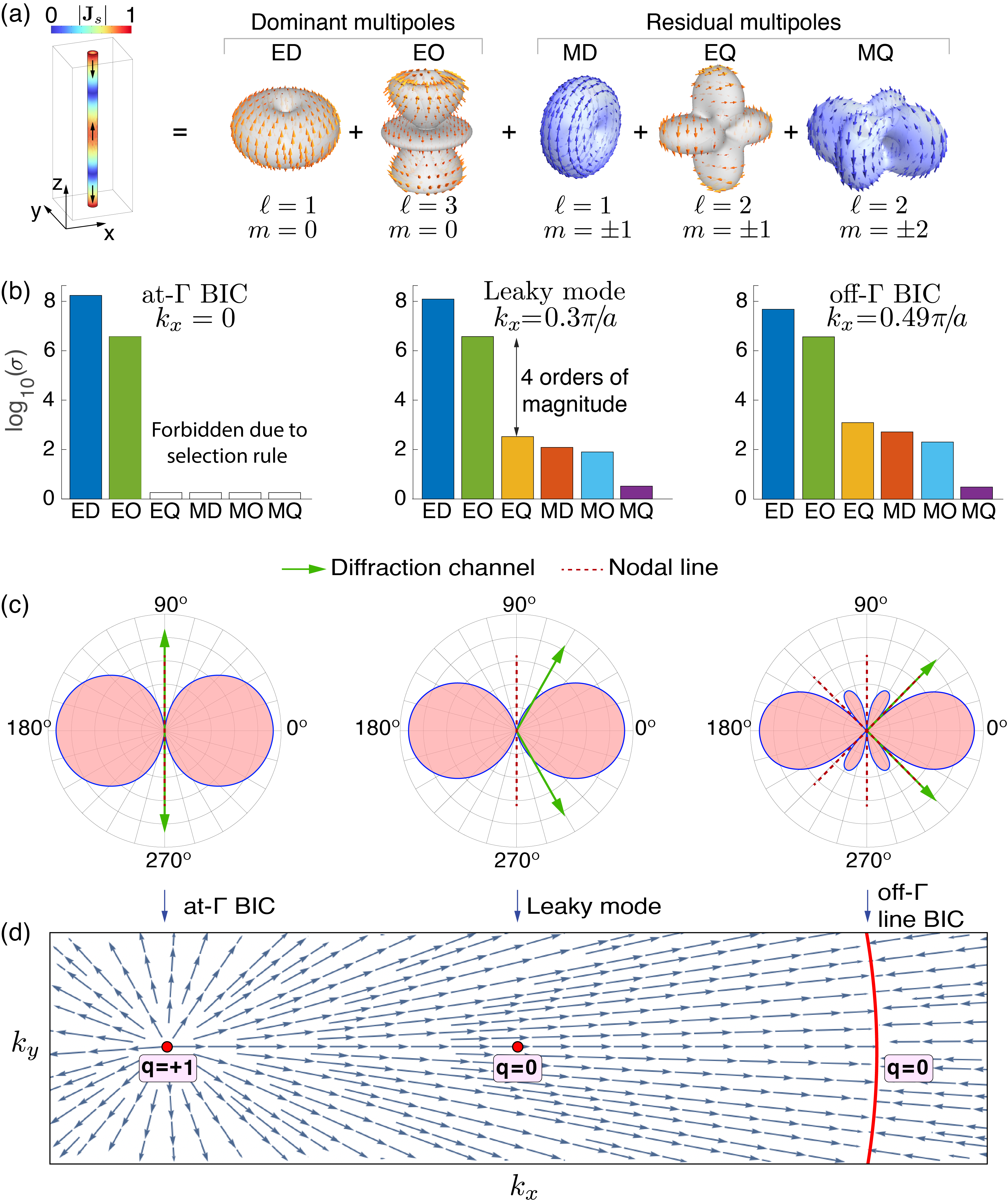
Figure 4(a) shows the multipolar general multipolar composition for the even plasma-like mode [] for the Bloch wavenumber along the direction. The multipolar harmonics are proportional to or , where is the azimuthal angle and is an integer. Because the unit cell is a thin wire ( and ), the main contribution is given only by the electrical multipoles with the rotation symmetry (), namely, vertical electric dipole, linear vertical electric octupole, etc. Figure 4(b) shows the amplitudes of the multipolar decomposition of the plasma-like mode for three different Bloch wavenumbers. The amplitudes are calculated by integrating the currents over the surface of the PEC wire [38]. One can see that the multipoles without rotating symmetry are suppressed at least by four orders of magnitude. This suppression ratio can be even higher for thinner wires. Figure 4(c) shows the numerically calculated directivity diagrams for the currents in the unit cell corresponding to at- BIC, leaky mode, and off- BIC. The Bloch wavenumbers are taken the same as in Fig. 4(b). The calculations demonstrate that both accidental and off- BICs are formed when the nodal lines of the directivity diagram (dashed red lines) coincide with the direction of the open diffraction channel (green arrows). It is worth mentioning that the directivity diagram remain symmetric with respect to the vertical axis even for non-zero Bloch wavenumbers indicating that the higher-order multipoles are suppressed.
BICs and the leaky states at the neighbor Bloch wavenumbers form a polarization vortex with a singularity at its center. Thus, BIC can be associated with polarization singularity carrying a topological charge which is usually defined as a winding number of the vortex [7]. The rigorous way for calculation of the topological charge of a BIC includes the finding of the far-field for the leaky states around the BIC followed by integration:
| (6) |
Here , and the complex amplitudes of the radiated plane waves, and is a simple counterclockwise oriented path enclosing the singular point. However, the far-field polarization structure and topological charge can be predicted using the multipolar decomposition of the polarization currents in the unit cell [44]. In combination with the group theory, this is a powerful tool for the analysis of the far-field polarization singularities of metasurfaces and single nanostructures [46, 47, 45, 48].
The EMA correctly predicts the frequency and angular position of symmetry-protected and accidental BICs [see Fig. 3] but does not completely describe their topological properties. The EMA neglects the internal structure of the wire medium and keeps only the multipoles with the rotational symmetry (), i.e. all in-plane directions are assumed to be identical [49, 50, 51]. Therefore, the accidental BIC within EMA forms a ring in the k-space [52, 53, 46]. Figure 4(h) shows the polarization map calculated within EMA. One can see that the topological charge of the symmetry-protected BIC is , while the accidental BIC forms a ring in the k-space for which topological charge is ill-defined with Eq. (6). The account for higher-order multipoles with transforms the ring of BICs to the ring of quasi-BIC with the genuine BICs only along the high-symmetry directions. However, it is difficult to distinguish this transformation even numerically as the amplitudes of higher-order multipoles are substantially suppressed. To visualize this transformation one can increase the radius of the wires (see the Supplemental Material [38]).
In summary, we have shown that the strong spatial dispersion in a slab of a wire medium composed of thin metallic wires results in the appearance of bound states in the continuum forming in an unusual way. The spatial dispersion makes possible propagation of longitudinal plasma-like waves. These waves form a symmetry-protected BIC in the -point, as they polarization orthogonal to the transversal waves in the surrounding space. The accidental BICs are formed due to the destructive interference of plasma-like waves and TEM waves according to the Friedrich-Wintgen scenario. Interaction between these waves occurs through the boundary of the slab that is formally described by the additional boundary conditions. Both types of BICs are well-described within effective medium approximation without the use of Bloch theorem and diffraction effects. We also show that the found BICs have a topological nature carrying an integer topological charge. An interesting feature of the revealed BICs is that they have no near-field within EMA being completely localized inside the structure in contrast to the conventional BICs in periodic metasurfaces. This property of BICs can be prospective for avoiding cross-talks in compact integrated photonic circuits. The developed theory of BICs is general and it can be equally applied to photonic, phononic, magnonic, and excitonic systems enhancing the capabilities of acoustic, magnetic, and polaritonic devices as the spatial dispersion effects in such systems can play a crucial role [54, 55].
Acknowledgement
The authors acknowledge useful discussions with Dmitriy Maksimov, Kirill Koshelev, Yuri Kivshar, and Mihail Petrov. The authors acknowledge Grigoriy Karsakov for technical support. The work is supported by the Federal program Priority 2030, the Russian Science Foundation, and the BASIS Foundation.
References
- Hsu et al. [2016] C. W. Hsu, B. Zhen, A. D. Stone, J. D. Joannopoulos, and M. Soljačić, Bound states in the continuum, Nat. Rev. Mater. 1, 1 (2016).
- Koshelev et al. [2023] K. L. Koshelev, Z. F. Sadrieva, A. A. Shcherbakov, Yu. S. Kivshar, and A. A. Bogdanov, Bound states in the continuum in photonic structures, Phys.-Usp. 66, 494 (2023).
- Liu and Xiao [2024] T. Liu and M. Xiao, A journey through bound states in the continuum in periodic optical structures, in Photonics Insights, Vol. 3, Issue 2, Vol. 3 (SPIE, 2024) p. C05.
- Kang et al. [2023] M. Kang, T. Liu, C. T. Chan, and M. Xiao, Applications of bound states in the continuum in photonics, Nat. Rev. Phys. 5, 659 (2023).
- Azzam and Kildishev [2021] S. I. Azzam and A. V. Kildishev, Photonic Bound States in the Continuum: From Basics to Applications, Adv. Opt. Mater. 9, 2001469 (2021).
- Xu et al. [2023] G. Xu, H. Xing, Z. Xue, D. Lu, J. Fan, J. Fan, P. P. Shum, and L. Cong, Recent Advances and Perspective of Photonic Bound States in the Continuum, Ultrafast Science 3, 10.34133/ultrafastscience.0033 (2023).
- Zhen et al. [2014] B. Zhen, C. W. Hsu, L. Lu, A. D. Stone, and M. Soljačić, Topological Nature of Optical Bound States in the Continuum, Phys. Rev. Lett. 113, 257401 (2014).
- Kodigala et al. [2017] A. Kodigala, T. Lepetit, Q. Gu, B. Bahari, Y. Fainman, and B. Kanté, Lasing action from photonic bound states in continuum, Nature 541, 196 (2017).
- Yu et al. [2021] Y. Yu, A. Sakanas, A. R. Zali, E. Semenova, K. Yvind, and J. Mørk, Ultra-coherent Fano laser based on a bound state in the continuum, Nat. Photonics 15, 758 (2021).
- Hwang et al. [2021] M.-S. Hwang, H.-C. Lee, K.-H. Kim, K.-Y. Jeong, S.-H. Kwon, K. Koshelev, Y. Kivshar, and H.-G. Park, Ultralow-threshold laser using super-bound states in the continuum, Nat. Commun. 12, 1 (2021).
- Wu et al. [2020] M. Wu, S. T. Ha, S. Shendre, E. G. Durmusoglu, W.-K. Koh, D. R. Abujetas, J. A. Sánchez-Gil, R. Paniagua-Domínguez, H. V. Demir, and A. I. Kuznetsov, Room-Temperature Lasing in Colloidal Nanoplatelets via Mie-Resonant Bound States in the Continuum, Nano Lett. 20, 6005 (2020).
- Romano et al. [2019] S. Romano, G. Zito, S. N. L. Yépez, S. Cabrini, E. Penzo, G. Coppola, I. Rendina, and V. Mocellaark, Tuning the exponential sensitivity of a bound-state-in-continuum optical sensor, Opt. Express 27, 18776 (2019).
- Romano et al. [2018] S. Romano, G. Zito, S. Torino, G. Calafiore, E. Penzo, G. Coppola, S. Cabrini, I. Rendina, and V. Mocella, Label-free sensing of ultralow-weight molecules with all-dielectric metasurfaces supporting bound states in the continuum, Photonics Res. 6, 726 (2018).
- Kravtsov et al. [2020] V. Kravtsov, E. Khestanova, F. A. Benimetskiy, T. Ivanova, A. K. Samusev, I. S. Sinev, D. Pidgayko, A. M. Mozharov, I. S. Mukhin, M. S. Lozhkin, Y. V. Kapitonov, A. S. Brichkin, V. D. Kulakovskii, I. A. Shelykh, A. I. Tartakovskii, P. M. Walker, M. S. Skolnick, D. N. Krizhanovskii, and I. V. Iorsh, Nonlinear polaritons in a monolayer semiconductor coupled to optical bound states in the continuum, Light Sci. Appl. 9, 1 (2020).
- Ardizzone et al. [2022] V. Ardizzone, F. Riminucci, S. Zanotti, A. Gianfrate, M. Efthymiou-Tsironi, D. G. Suàrez-Forero, F. Todisco, M. De Giorgi, D. Trypogeorgos, G. Gigli, K. Baldwin, L. Pfeiffer, D. Ballarini, H. S. Nguyen, D. Gerace, and D. Sanvitto, Polariton Bose–Einstein condensate from a bound state in the continuum, Nature 605, 447 (2022).
- Koshelev et al. [2019a] K. Koshelev, Y. Tang, K. Li, D.-Y. Choi, G. Li, and Y. Kivshar, Nonlinear Metasurfaces Governed by Bound States in the Continuum, ACS Photonics 6, 1639 (2019a).
- Liu et al. [2019a] Z. Liu, Y. Xu, Y. Lin, J. Xiang, T. Feng, Q. Cao, J. Li, S. Lan, and J. Liu, High- Quasibound States in the Continuum for Nonlinear Metasurfaces, Phys. Rev. Lett. 123, 253901 (2019a).
- Koshelev et al. [2020] K. Koshelev, S. Kruk, E. Melik-Gaykazyan, J.-H. Choi, A. Bogdanov, H.-G. Park, and Y. Kivshar, Subwavelength dielectric resonators for nonlinear nanophotonics, Science 367, 288 (2020).
- Azzam et al. [2018] S. I. Azzam, V. M. Shalaev, A. Boltasseva, and A. V. Kildishev, Formation of Bound States in the Continuum in Hybrid Plasmonic-Photonic Systems, Phys. Rev. Lett. 121, 253901 (2018).
- Hsu et al. [2013] C. W. Hsu, B. Zhen, J. Lee, S.-L. Chua, S. G. Johnson, J. D. Joannopoulos, and M. Soljačić, Observation of trapped light within the radiation continuum, Nature 499, 188 (2013).
- Sadrieva et al. [2017] Z. F. Sadrieva, I. S. Sinev, K. L. Koshelev, A. Samusev, I. V. Iorsh, O. Takayama, R. Malureanu, A. A. Bogdanov, and A. V. Lavrinenko, Transition from Optical Bound States in the Continuum to Leaky Resonances: Role of Substrate and Roughness, ACS Photonics 4, 723 (2017).
- Friedrich and Wintgen [1985] H. Friedrich and D. Wintgen, Interfering resonances and bound states in the continuum, Phys. Rev. A 32, 3231 (1985).
- Gomis-Bresco et al. [2017] J. Gomis-Bresco, D. Artigas, and L. Torner, Anisotropy-induced photonic bound states in the continuum, Nat. Photonics 11, 232 (2017).
- Quotane et al. [2018] I. Quotane, E. H. El Boudouti, and B. Djafari-Rouhani, Trapped-mode-induced Fano resonance and acoustical transparency in a one-dimensional solid-fluid phononic crystal, Phys. Rev. B 97, 024304 (2018).
- Mizuno [2019] S. Mizuno, Fano resonances and bound states in the continuum in a simple phononic system, Appl. Phys. Express 12, 035504 (2019).
- Deriy et al. [2022] I. Deriy, I. Toftul, M. Petrov, and A. Bogdanov, Bound States in the Continuum in Compact Acoustic Resonators, Phys. Rev. Lett. 128, 084301 (2022).
- Belov et al. [2003] P. A. Belov, R. Marqués, S. I. Maslovski, I. S. Nefedov, M. Silveirinha, C. R. Simovski, and S. A. Tretyakov, Strong spatial dispersion in wire media in the very large wavelength limit, Phys. Rev. B 67, 113103 (2003).
- Simovski et al. [2012] C. R. Simovski, P. A. Belov, A. V. Atrashchenko, and Y. S. Kivshar, Wire Metamaterials: Physics and Applications, Adv. Mater. 24, 4229 (2012).
- Silveirinha [2006] M. G. Silveirinha, Additional boundary condition for the wire medium, IEEE Trans. Antennas Propag. 54, 1766 (2006).
- Silveirinha [2009] M. G. Silveirinha, Artificial plasma formed by connected metallic wires at infrared frequencies, Phys. Rev. B 79, 035118 (2009).
- Maslovski et al. [2002] S. I. Maslovski, S. A. Tretyakov, and P. A. Belov, Wire media with negative effective permittivity: A quasi-static model, Microwave Opt. Technol. Lett. 35, 47 (2002).
- Silveirinha and Yakovlev [2010] M. G. Silveirinha and A. B. Yakovlev, Negative refraction by a uniaxial wire medium with suppressed spatial dispersion, Phys. Rev. B 81, 233105 (2010).
- Simovski and Belov [2004] C. R. Simovski and P. A. Belov, Low-frequency spatial dispersion in wire media, Phys. Rev. E 70, 046616 (2004).
- Belov et al. [2005] P. A. Belov, C. R. Simovski, and P. Ikonen, Canalization of subwavelength images by electromagnetic crystals, Phys. Rev. B 71, 193105 (2005).
- Ktorza et al. [2015] I. Ktorza, L. Ceresoli, S. Enoch, S. Guenneau, and R. Abdeddaim, Single frequency microwave cloaking and subwavelength imaging with curved wired media, Opt. Express 23, 10319 (2015).
- Ikonen et al. [2006] P. Ikonen, P. Belov, C. Simovski, and S. Maslovski, Experimental demonstration of subwavelength field channeling at microwave frequencies using a capacitively loaded wire medium, Phys. Rev. B 73, 073102 (2006).
- Silveirinha et al. [2008] M. G. Silveirinha, C. A. Fernandes, and J. R. Costa, Additional boundary condition for a wire medium connected to a metallic surface, New J. Phys. 10, 053011 (2008).
- [38] See Supplemental Material at URL-will-be-inserted-by-publisher for the data of the experiments.
- Wang et al. [2023] W. Wang, A. Günzler, B. D. Wilts, U. Steiner, and M. Saba, Unconventional bound states in the continuum from metamaterial-induced electron acoustic waves, in Advanced Photonics, Vol. 5, Issue 5, Vol. 5 (SPIE, 2023) p. 056005.
- Koshelev et al. [2019b] K. Koshelev, A. Bogdanov, and Y. Kivshar, Meta-optics and bound states in the continuum, Science Bulletin 64, 836 (2019b).
- Bulgakov and Maksimov [2017] E. N. Bulgakov and D. N. Maksimov, Bound states in the continuum and polarization singularities in periodic arrays of dielectric rods, Phys. Rev. A 96, 063833 (2017).
- Liu et al. [2019b] W. Liu, B. Wang, Y. Zhang, J. Wang, M. Zhao, F. Guan, X. Liu, L. Shi, and J. Zi, Circularly Polarized States Spawning from Bound States in the Continuum, Phys. Rev. Lett. 123, 116104 (2019b).
- Jin et al. [2019] J. Jin, X. Yin, L. Ni, M. Soljačić, B. Zhen, and C. Peng, Topologically enabled ultrahigh-Q guided resonances robust to out-of-plane scattering, Nature 574, 501 (2019).
- Sadrieva et al. [2019] Z. Sadrieva, K. Frizyuk, M. Petrov, Y. Kivshar, and A. Bogdanov, Multipolar origin of bound states in the continuum, Physical Review B 100, 115303 (2019).
- Chen et al. [2019] W. Chen, Y. Chen, and W. Liu, Singularities and Poincaré Indices of Electromagnetic Multipoles, Phys. Rev. Lett. 122, 153907 (2019).
- Gladyshev et al. [2022] S. Gladyshev, A. Shalev, K. Frizyuk, K. Ladutenko, and A. Bogdanov, Bound states in the continuum in multipolar lattices, Phys. Rev. B 105, L241301 (2022).
- Gladyshev et al. [2020] S. Gladyshev, K. Frizyuk, and A. Bogdanov, Symmetry analysis and multipole classification of eigenmodes in electromagnetic resonators for engineering their optical properties, Phys. Rev. B 102, 075103 (2020).
- Volkovskaya et al. [2020] I. Volkovskaya, L. Xu, L. Huang, A. I. Smirnov, A. E. Miroshnichenko, and D. Smirnova, Multipolar second-harmonic generation from high-Q quasi-BIC states in subwavelength resonators, Nanophotonics 9, 3953 (2020).
- Gorlach and Belov [2015] M. A. Gorlach and P. A. Belov, Nonlocality in uniaxially polarizable media, Phys. Rev. B 92, 085107 (2015).
- Petschulat et al. [2008] J. Petschulat, C. Menzel, A. Chipouline, C. Rockstuhl, A. Tunnermann, F. Lederer, and T. Pertsch, Multipole approach to metamaterials, Phys. Rev. A 78, 043811 (2008).
- Yaghjian et al. [2013] A. D. Yaghjian, A. Alù, and M. G. Silveirinha, Homogenization of spatially dispersive metamaterial arrays in terms of generalized electric and magnetic polarizations, Photonics Nanostruct. Fundam. Appl. 11, 374 (2013).
- Kostyukov et al. [2022] A. S. Kostyukov, V. S. Gerasimov, A. E. Ershov, and E. N. Bulgakov, Ring of bound states in the continuum in the reciprocal space of a monolayer of high-contrast dielectric spheres, Phys. Rev. B 105, 075404 (2022).
- Bulgakov and Maksimov [2019] E. N. Bulgakov and D. N. Maksimov, Bound states in the continuum and Fano resonances in the Dirac cone spectrum, J. Opt. Soc. Am. B, JOSAB 36, 2221 (2019).
- Basov et al. [2016] D. N. Basov, M. M. Fogler, and F. J. G. de Abajo, Polaritons in van der Waals materials, Science 354, 10.1126/science.aag1992 (2016).
- Bossart and Fleury [2023] A. Bossart and R. Fleury, Extreme Spatial Dispersion in Nonlocally Resonant Elastic Metamaterials, Phys. Rev. Lett. 130, 207201 (2023).