Emergent spin and orbital angular momentum of light in twisted photonic bilayer
Abstract
We demonstrate that the optical response of twisted photonic bilayers is sensitive to both spin angular momentum (SAM) and orbital angular momentum (OAM) of light. Due to the transfer of the angular momenta between the light and the bilayer, optical beams with zero SAM and OAM acquire SAM upon transmission and OAM upon reflection. Our numerical calculations and the developed analytical theory show that the values of the emergent SAM and OAM depend differently on the interlayer distance and can be controlled by tuning the twist angle. The predicted phenomena do not require light absorption and are caused by the helicity-dependent light diffraction on the moiré pattern, which inevitably occurs in the twisted structure, and SAM-OAM conversion. We also reveal strong SAM and OAM in the moiré-diffracted beams.
I Introduction
Chiral objects, which are different from their mirror image, are famous for their ability to interact differently with photons of right-handed and left-handed circular polarizations, i.e., photons with the opposite projections of spin angular momentum (SAM). This results in circular birefringence (CB) and circular dichroism (CD) manifesting, respectively, as the rotation of the polarization plane of linearly polarized light passing through the chiral medium and the emergence of a partial circular polarization for initially unpolarized beam [1, 2]. Recently, it became acknowledged that, in addition to SAM, photons can also possess orbital angular momentum (OAM) associated with the winding number of the wave phase [3, 4] and chiral structures can discriminate beams with opposite OAM projections giving rise to optical vortex (or helical) birefringence and vortex dichroism (VD) [5, 6]. For chiral molecules, which are much smaller than the light wavelength, VD becomes possible only beyond the electro-dipole electron-photon interaction [7, 8] or beyond the paraxial approximation [9]. Similarly to CD, VD can be used to distinguish enantiomers while providing extra sensitivity to the quadrupole transitions [10]. VD is also demonstrated for wavelength-scale particles made of chiral media [11, 12] or asymmetrically-shaped objects made of achiral media [13, 14]. Furthermore, the Raman scattering by chiral molecules can be sensitive to the OAM of light [15, 16] and, conversely, a beam with OAM can induce chirality in structures with nonlinear susceptibility [17, 18].
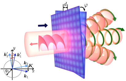
To enable chiral response in solid state optics, planar waveguides and microcavities with lithographically patterned chiral elements are proposed [19, 20]. Another approach to create a solid state chiral metasurface is to take a pair of achiral photonic layers and stack them with a twist [21], as shown in Fig. 1. Such a design provides additional tunabilty through the control of the twist angle and the interlayer distance . It is inspired by twisted van der Waals crystals, such as bilayer graphene, where the fine tuning of the twist angle enables the emergence of electronic flat bands and superconductivity [22, 23], and twisted TMDC heterostructures exhibiting intrinsic circularly polarized exciton emission [24]. Twisted bilayers of optical lattices for cold atoms [25, 26], mechanical crystals [27, 28], and nodal superconductors [29] are also considered. In twisted photonic lattices, light localization due to the optical flat bands [30], formation of solitons [31], the edge, corner, and other twist-dependent optical modes [32, 33, 34] are reported. However, the aforementioned effects are caused by the in-plane moiré modulation and do not require the chirality per se. The study of chiral optical response is limited so far to CD and CB, which was demonstrated for twisted bilayer graphene [35] and twisted stacks of other 2D semiconductors [36] as well as their optical counterparts [37, 38].
In this paper, we show that twisted photonic bilayers exhibit both SAM- and OAM-dependent response. In particular, the incident optical beam with zero SAM (i.e., unpolarized) and zero OAM acquires SAM and OAM upon transmission and reflection. While the two phenomena might seem conceptually similar, we reveal that they have rather different nature, which leads to their very distinct properties: (i) SAM decays with the interlayer distance while OAM oscillates and (ii) SAM is observed in transmission while OAM is maximal in reflection. Moreover, we show that both phenomena do not require light absorption and are observed also in transparent bilayers. The emergence of SAM in the transmitted beam is caused by the diffraction of light by the moiré pattern, which inevitably occurs in the twisted structure and appears to be highly sensitive to the helicity of incident photons. We also study the parameters of the moiré diffracted beams and show that the beams possess significant SAM and OAM.
II Model and Method
We consider a chiral bilayer consisting of two () thin dielectric slabs, Fig. 1. The layers are positioned at , and rotated relatively to each other by the angle . The permittivity of each layer is assumed to be periodically modulated in the form of a square lattice with the period , so that the in-plane polarizations are given by
| (1) |
where is the in-plane coordinate, is the uniform component of the layer polarizability and is the amplitude of its spatial modulation, and are the reciprocal lattice vectors of the modulation, , , , and is the local in-plane electric field.
The bilayer is illuminated by normally-incident monochromatic optical beam with the electric field where is the in-plane Fourier image, , , and is the radiation frequency. We consider Gaussian beams, with the width , so that the paraxial approximation is applicable and the electric field polarization can be assumed constant.
Solution of the Maxwell equations yields the field distribution in the whole space in the form, see Appendix A,
| (2) |
where is the Fourier harmonic of the scattered field and the summation is performed over all diffraction wave vectors
| (3) |
with integer and . We focus on the “metasurface” regime when the period of permittivity modulation in the layers is smaller than the wave length of incident light (). Then, individual layers do not produce propagating diffracted beams. However, in twisted bilayers, because of coupling via near fields, the diffraction by the moiré pattern becomes possible, since its wave vector can be smaller than , see Fig. 1.
For the incident beam much wider than the moiré scale (), the diffracted beams of different orders do not overlap in -space. Then, the Fourier components of the transmitted and reflected beams can be related to those of the incident beam via the 22 polarization Jones matrices and . Similarly, we introduce the Jones matrices and for the diffracted beams with propagating forward and backward, respectively, see Appendix A.
In the basis of circularly polarized plane waves (), the point-group symmetry of the bilayer, together with Lorentz reciprocity, imposes the constrains on the transmission and reflection coefficients at . At transmission, the sign of the circular polarization is conserved, , however enabling the emergence of SAM even for unpolarized incident beam. In reflection, and (we define the sign of the circular polarization with respect to the beam propagation direction), and the SAM vanishes. To understand the emergence of OAM one should consider optical beams constructed from plane waves with . At finite , the above constrains on the transmission and reflection coefficients are violated. The SAM-OAM conversion processes such as , where and are the OAM and SAM projections, get allowed. The difference in the amplitudes of these processes results in the OAM in the reflected beam even if the incident beam carries no OAM.
III Results
We now discuss the properties of the transmitted, reflected, and diffracted beams. We characterize each beam by the intensity, the SAM (the degree of circular polarization), and the OAM . The latter is calculated using the operator where is unit vector in the direction of beam propagation.
III.1 Transmitted and reflected beam
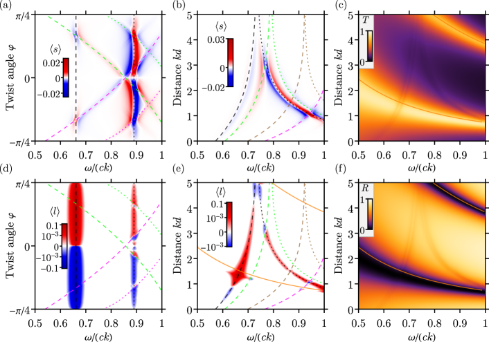
First, we discuss the transmitted and reflected beams. We suppose that the incident beam is unpolarized, i.e., consists of incoherent and contributions. Figure 2 reveals that the transmitted beam acquires SAM [Figs. 2(a) and 2(b)] while the reflected beam acquires OAM [Figs. 2(d) and 2(e)]. Both effects are odd in the twist angle and vanish at when the bilayer lacks chirality, see Figs. 2(a) and 2(d).
The optical response of the bilayer contains the Fabry-Pérot resonances (solid lines in Fig. 2) and the resonances associated with the guided modes confined between the two layers (dashed and dotted lines in Fig. 2) [37]. The frequencies of the symmetric and antisymmetric guided modes with the in-plane wave vector and of the Fabry-Pérot resonances with in the limit of vanishing are determined by
| (4) |
where are the diffraction vectors determined by Eq. (3). The in-plane modulation of the permittivity couples the guided modes to the free-space modes, therefore they acquire finite lifetime and can be excited by normally incident beam. The resonances are clearly seen in the transmittance and reflectance, see Figs. 2(c) and 2(f), respectively. Both SAM and OAM are enhanced at the resonances. For our case of weak dielectric modulation , the enhancement is particularly pronounced at the frequencies of the guided modes with the first-order diffraction wave vectors (black dashed and dotted lines in Fig. 2). The OAM of the reflected beam is additionally increased at the intersections of the guided modes with the Fabry-Pérot modes, where the conventional reflection is suppressed.
Though the SAM (circular polarization) of the beam transmitted through the chiral bilayer may seem to be natural, its microscopic origin is in fact unusual and differs from the known mechanism. In conventional chiral media, the circular polarization of the transmitted (initially unpolarized) beam is caused by the circular dichroism, i.e., the difference in the absorption of and waves. Here, the circular polarization emerges even in the absence of absorption. Surprisingly, the transmission coefficients for and photons are different although the photons retain their helicity and the reflection coefficients for and photons coincide. This puzzle is solved by taking into account the moiré pattern of twisted bilayers and unavoidable diffraction by the moiré wave vectors. In chiral bilayers, the intensity of the diffracted beams depends on the circular polarization of the incident beam. This difference in the decay of incident and photons over the diffraction channels gives rise to the circular polarization of the transmitted beam.
Simple analytic expressions for the SAM and OAM can be obtained in the case of small layer polarizability, , i.e. away from the resonances, see Appendix B. The spin-dependent contribution to the transmission coefficient comes from the fourth-order diffraction processes, e.g., consequently by , , , . For small , the SAM of the transmitted beam assumes the form
| (5) |
where is the reciprocal decay length of the near field. As the function of the interlayer distance , the SAM rises linearly at small , reaches maximum at , and then decreases exponentially at large . Such a non-monotonous dependence also persists in the full calculation Fig. 2(b), where the SAM is shown as a function of the light frequency and the interlayer distance. The exponential decrease at large clearly indicates that the SAM originates from the near field interaction between the layers. Indeed, at large interlayer distances , the interaction of light with each layer can be considered independently. Since the individual layer possesses high symmetry ( point group), it exhibits polarization-independent transmission and reflection in the paraxial approximation, so that the SAM vanishes.
The OAM for the reflected beam arises already in the second-order diffraction processes, e.g., consequently by and . Such processes occur from individual layers and lead to distortions of the Gaussian beam shape. Interference of the distortions induced by the first and the second layer leads to the OAM
| (6) |
Similarly to the SAM, the OAM vanishes at and reaches its maxima at the twist angle . However, being determined by the interference of the far fields rather than by the near fields, the OAM does not decay with the increase of the interlayer distance. In transmission, the optical paths of the beams distorted by the first and second layer are the same, suppressing their interference and leading to a much smaller value of the OAM than for the reflected beam.
III.2 Moiré diffracted beams
The emergence of moiré pattern in twisted bilayers gives rise to a series of propagating diffracted beams with the in-plane wave vectors . To the lowest order in the permittivity modulation, there are four forward diffracted beams with the in-plane wave vectors and , where and . In the bilayers with small twist angles , these beams slightly deviate from the incident beam direction.
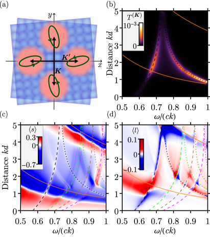
The diffracted beams are considerably polarized even for the unpolarized incident beam. Their polarization, in general, is elliptical, as sketched by green ellipses in Fig. 3(a), which results from the bilayer twist. Typically, the beams have strong linear polarization degree along the corresponding diffraction wave vectors.
Figure 3(b) shows the intensity of the diffracted beams as a function of the interlayer distance and light frequency. The moiré diffraction stems from the near field interaction and, therefore, is highly sensitive to the interlayer distance. The diffraction is most prominent at the waveguide resonances. The SAM and OAM are shown in Figs. 3(c) and 3(d). The diffracted beam acquires much larger spin and orbital angular momenta than the transmitted or reflected beams. This is especially noticeable for the SAM, Fig. 3(c).
In the case of small layer polarizability, , the analytic expression for amplitudes of the moiré diffracted beams can be obtained, see Appendix B. For small twist angles, , the SAM and OAM assume the form
| (7) | ||||
| (8) |
The SAM and OAM in the diffracted beams are much larger than those in the transmitted and reflected beams since the very occurrence of diffracted beams originates from the structure twist.
III.3 Field distribution in interference zone
Finally, we consider the polarization of the field behind the bilayer in the far zone at . In this region, the near field vanishes but the transmitted beam interferes with the forward diffracted beams. Thus, the total field reads
| (9) |
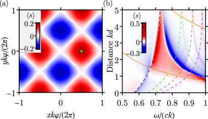
Now, we assume that the incident beam is linearly polarized at the angle to the axis. Due to the interference, the total field acquires strong local circular polarization which oscillates in the plane, see Fig. 4(a). The period of the oscillations is determined by the moiré pattern. Figure 4(b) shows the amplitude of the SAM spatial oscillations as a function of the interlayer distance and light frequency. The value of SAM at the waveguide resonances can be rather high.
In the case of small layer polarizability, , the spatial distribution of the SAM in the interference zone is given by
| (10) | ||||
The spin polarization follows dependence on the polarization direction of the incident light, as in a birefrigent medium. This local birefringence is induced by the moiré pattern and has maxima at the positions , where and are integers with different parity.
IV Summary
To summarize, we have developed a theory of the spin and orbital chiral optical response of a twisted photonic bilayer consisting of dielectric slabs with in-plane modulation of permittivity. Using the scattering formalism, we have calculated the Jones matrices relating the electric field of incident light with the electric fields of transmitted, reflected, and diffracted by the moiré pattern beams and studied the parameters of the beams as a function of the twist angle and the interlayer distance.
The interaction of light with twisted photonic bilayer includes the transfer of angular momentum. As a result, initially unpolarized beam carrying no orbital angular momentum acquires spin angular momentum upon transmission and orbital angular momentum upon reflection. The effects are particularly pronounced at the frequencies of the eigen optical modes of the twisted bilayer. Both effects are sensitive to the interlayer distance but exhibit different behavior: the orbital angular momentum in reflection oscillates with a constant amplitude when the interlayer distance is increased while the spin angular momentum in transmission decays exponentially at large distances. The spin angular momentum emerges from the near field interaction in the twisted bilayer and the related diffraction by the moiré pattern. The origin of the orbital angular momentum is the interference of the asymmetric distortions of the beam induced by the two layers. The moiré diffracted beams are also found to carry significant spin and orbital angular momenta.
Acknowledgements.
E.S.V. acknowledges the support by the Russian Science Foundation (Project No. 23-12-00142).Appendix A Solution of the Maxwell equations
To calculate the electric field in the whole space we solve the wave equation
| (11) |
with the sheet polarizations given by Eq. (1). Substituting the solution in the form of Eq. (2), we obtain the amplitudes of the diffracted waves
| (12) |
where
| (13) |
is the dyadic Green function and . Note that the terms with in the electric field distribution Eq. (12) correspond to evanescent waves.
The Fourier harmonics of the polarization in Eq. (12) are determined by the electric field in the layers,
| (14) | ||||
| (15) |
which follows from Eq. (1). We solve the set of Eqs. (12) and (14) numerically and, in some approximations, analytically. In numerical solution, to smoothen the sharp resonances we use the regularization with small which corresponds to the medium with weak losses.
The Jones matrices and for Fourier components of the diffracted beams propagating forward and backward are defined as
| (16) | ||||
| (17) |
In particular, and determine the amplitudes of the transmitted and reflected beams.
Appendix B Perturbative approach
If the polarizabilities of the layers are small, , they can be considered as a perturbation. Then, the electric field of the scattered waves can be obtained by an iterative solution of Eqs. (12)–(14).
To calculate the SAM of the transmitted beam, the transmission matrix up to fourth order in shall be calculated. Indeed, for that the diffraction by both the first and the second layer should be taken into account, e.g., consequently by the reciprocal lattice vectors , , , . This yields the spin-dependent contribution to the transmission matrix
| (18) | ||||
| (19) |
where . In the case of small twist angle , the dominant contribution is given by the terms with , or , . Then, the result simplifies to
| (20) | ||||
For the case of non-polarized excitation, the SAM of the transmitted wave is calculated as
| (21) |
which yields Eq. (5).
To calculate the OAM for the reflected beam, it is sufficient to take into account the second-order diffraction processes. However, the finite width of the beam and the dependence of the reflection amplitude on the in-plane wave vector should be considered. The second-order contribution to the reflection matrix reads
| (22) | ||||
Now we expand to the second order in as follows
| (23) |
where we use the fact that the linear-in- terms vanish. Then, the OAM is readily expressed via the expansion coefficients
| (24) |
Substituting the explicit expression from Eq. (22), we arrive to Eq. (6)
The amplitude of the beams diffracted by the moiré wave vector is also obtained in the second order and reads
| (25) |
We expand to the first order in as follows
| (26) |
Then, the SAM and OAM are given by
| (27) |
respectively.
References
- Fresnel [1866] A. Fresnel, Mémoire sur la double réfraction que les rayons lumineux éprouvent en traversant les aiguilles de cristal de roche suivant les directions parallèles à l’axe, in Œuvres complètes d’Augustin Fresnel, Vol. I, edited by H. de Sénarmont, E. Verdet, and L. Fresnel (Imprimerie Impériale, Paris, 1866) pp. 731–751.
- Agranovich and Ginzburg [1984] V. M. Agranovich and V. L. Ginzburg, Crystal Optics with Spatial Dispersion, and Excitons (Springer Berlin Heidelberg, 1984).
- Bliokh and Nori [2015] K. Y. Bliokh and F. Nori, Transverse and longitudinal angular momenta of light, Physics Reports 592, 1–38 (2015).
- Knyazev and Serbo [2018] B. A. Knyazev and V. G. Serbo, Beams of photons with nonzero orbital angular momentum projection: new results, Phys. Usp. 61, 449 (2018).
- Babiker et al. [2018] M. Babiker, D. L. Andrews, and V. E. Lembessis, Atoms in complex twisted light, Journal of Optics 21, 013001 (2018).
- Forbes and Andrews [2021] K. A. Forbes and D. L. Andrews, Orbital angular momentum of twisted light: chirality and optical activity, Journal of Physics: Photonics 3, 022007 (2021).
- Andrews et al. [2004] D. Andrews, L. Romero, and M. Babiker, On optical vortex interactions with chiral matter, Optics Communications 237, 133–139 (2004).
- Forbes and Andrews [2018] K. A. Forbes and D. L. Andrews, Optical orbital angular momentum: twisted light and chirality, Optics Letters 43, 435 (2018).
- Forbes and Jones [2021] K. A. Forbes and G. A. Jones, Optical vortex dichroism in chiral particles, Phys. Rev. A 103, 053515 (2021).
- Brullot et al. [2016] W. Brullot, M. K. Vanbel, T. Swusten, and T. Verbiest, Resolving enantiomers using the optical angular momentum of twisted light, Science Advances 2, e1501349 (2016).
- Wang et al. [2023] J. Wang, Z. Cui, Y. Shi, S. Guo, and F. Wu, Vortical differential scattering of twisted light by dielectric chiral particles, Photonics 10, 237 (2023).
- Cui et al. [2021] Z. Cui, S. Guo, J. Wang, F. Wu, and Y. Han, Light scattering of Laguerre–Gaussian vortex beams by arbitrarily shaped chiral particles, Journal of the Optical Society of America A 38, 1214 (2021).
- Woźniak et al. [2019] P. Woźniak, I. De Leon, K. Höflich, G. Leuchs, and P. Banzer, Interaction of light carrying orbital angular momentum with a chiral dipolar scatterer, Optica 6, 961 (2019).
- Ni et al. [2021] J. Ni, S. Liu, G. Hu, Y. Hu, Z. Lao, J. Li, Q. Zhang, D. Wu, S. Dong, J. Chu, and C.-W. Qiu, Giant helical dichroism of single chiral nanostructures with photonic orbital angular momentum, ACS Nano 15, 2893–2900 (2021).
- Forbes [2019] K. A. Forbes, Raman optical activity using twisted photons, Phys. Rev. Lett. 122, 103201 (2019).
- Müllner et al. [2022] S. Müllner, F. Büscher, A. Möller, and P. Lemmens, Discrimination of chiral and helical contributions to Raman scattering of liquid crystals using vortex beams, Phys. Rev. Lett. 129, 207801 (2022).
- Bégin et al. [2023] J.-L. Bégin, A. Jain, A. Parks, F. Hufnagel, P. Corkum, E. Karimi, T. Brabec, and R. Bhardwaj, Nonlinear helical dichroism in chiral and achiral molecules, Nature Photonics 17, 82 (2023).
- Nikitina and Frizyuk [2024] A. Nikitina and K. Frizyuk, Achiral nanostructures: perturbative harmonic generation and dichroism under vortex and vector beams illumination, arXiv:2402.13947 (2024).
- Konishi et al. [2011] K. Konishi, M. Nomura, N. Kumagai, S. Iwamoto, Y. Arakawa, and M. Kuwata-Gonokami, Circularly polarized light emission from semiconductor planar chiral nanostructures, Phys. Rev. Lett. 106, 057402 (2011).
- Maksimov et al. [2014] A. A. Maksimov, I. I. Tartakovskii, E. V. Filatov, S. V. Lobanov, N. A. Gippius, S. G. Tikhodeev, C. Schneider, M. Kamp, S. Maier, S. Höfling, and V. D. Kulakovskii, Circularly polarized light emission from chiral spatially-structured planar semiconductor microcavities, Phys. Rev. B 89, 045316 (2014).
- Han et al. [2023] Z. Han, F. Wang, J. Sun, X. Wang, and Z. Tang, Recent advances in ultrathin chiral metasurfaces by twisted stacking, Advanced Materials 35, 2206141 (2023).
- Cao et al. [2018] Y. Cao, V. Fatemi, S. Fang, K. Watanabe, T. Taniguchi, E. Kaxiras, and P. Jarillo-Herrero, Unconventional superconductivity in magic-angle graphene superlattices, Nature 556, 43–50 (2018).
- Törmä et al. [2022] P. Törmä, S. Peotta, and B. A. Bernevig, Superconductivity, superfluidity and quantum geometry in twisted multilayer systems, Nature Reviews Physics 4, 528–542 (2022).
- Michl et al. [2022] J. Michl, C. C. Palekar, S. A. Tarasenko, F. Lohof, C. Gies, M. von Helversen, R. Sailus, S. Tongay, T. Taniguchi, K. Watanabe, T. Heindel, B. Rosa, M. Rödel, T. Shubina, S. Höfling, S. Reitzenstein, C. Anton-Solanas, and C. Schneider, Intrinsic circularly polarized exciton emission in a twisted van der Waals heterostructure, Phys. Rev. B 105, L241406 (2022).
- González-Tudela and Cirac [2019] A. González-Tudela and J. I. Cirac, Cold atoms in twisted-bilayer optical potentials, Phys. Rev. A 100, 053604 (2019).
- Meng et al. [2023] Z. Meng, L. Wang, W. Han, F. Liu, K. Wen, C. Gao, P. Wang, C. Chin, and J. Zhang, Atomic Bose–Einstein condensate in twisted-bilayer optical lattices, Nature 615, 231–236 (2023).
- Deng et al. [2020] Y. Deng, M. Oudich, N. J. Gerard, J. Ji, M. Lu, and Y. Jing, Magic-angle bilayer phononic graphene, Phys. Rev. B 102, 180304 (2020).
- Rosendo López et al. [2020] M. Rosendo López, F. Peñaranda, J. Christensen, and P. San-Jose, Flat bands in magic-angle vibrating plates, Phys. Rev. Lett. 125, 214301 (2020).
- Volkov et al. [2023] P. A. Volkov, J. H. Wilson, K. P. Lucht, and J. H. Pixley, Magic angles and correlations in twisted nodal superconductors, Phys. Rev. B 107, 174506 (2023).
- Wang et al. [2019] P. Wang, Y. Zheng, X. Chen, C. Huang, Y. V. Kartashov, L. Torner, V. V. Konotop, and F. Ye, Localization and delocalization of light in photonic moiré lattices, Nature 577, 42–46 (2019).
- Fu et al. [2020] Q. Fu, P. Wang, C. Huang, Y. V. Kartashov, L. Torner, V. V. Konotop, and F. Ye, Optical soliton formation controlled by angle twisting in photonic moiré lattices, Nature Photonics 14, 663–668 (2020).
- Lu et al. [2023] C. Lu, Y. Gao, X. Cao, Y. Ren, Z. Han, Y. Cai, and Z. Wen, Linear and nonlinear edge and corner states in graphenelike moiré lattices, Phys. Rev. B 108, 014310 (2023).
- Arkhipova et al. [2023] A. A. Arkhipova, Y. V. Kartashov, S. K. Ivanov, S. A. Zhuravitskii, N. N. Skryabin, I. V. Dyakonov, A. A. Kalinkin, S. P. Kulik, V. O. Kompanets, S. V. Chekalin, F. Ye, V. V. Konotop, L. Torner, and V. N. Zadkov, Observation of linear and nonlinear light localization at the edges of moiré arrays, Phys. Rev. Lett. 130, 083801 (2023).
- Salakhova et al. [2023] N. S. Salakhova, I. M. Fradkin, S. A. Dyakov, and N. A. Gippius, Twist-tunable moiré optical resonances, Phys. Rev. B 107, 155402 (2023).
- Kim et al. [2016] C.-J. Kim, A. Sánchez-Castillo, Z. Ziegler, Y. Ogawa, C. Noguez, and J. Park, Chiral atomically thin films, Nature Nanotechnology 11, 520 (2016).
- Poshakinskiy et al. [2018] A. V. Poshakinskiy, D. R. Kazanov, T. V. Shubina, and S. A. Tarasenko, Optical activity in chiral stacks of 2D semiconductors, Nanophotonics 7, 753–762 (2018).
- Lou et al. [2021] B. Lou, N. Zhao, M. Minkov, C. Guo, M. Orenstein, and S. Fan, Theory for twisted bilayer photonic crystal slabs, Phys. Rev. Lett. 126, 136101 (2021).
- Tang et al. [2023] H. Tang, B. Lou, F. Du, M. Zhang, X. Ni, W. Xu, R. Jin, S. Fan, and E. Mazur, Experimental probe of twist angle-dependent band structure of on-chip optical bilayer photonic crystal, Science Advances 9, eadh8498 (2023).