3D Orbital Angular Momentum Nonlinear Holography
Abstract
Orbital angular momentum (OAM), due to its theoretically orthogonal and unbounded helical phase index, has been utilized as an independent physical degree of freedom for ultrahigh-capacity information encryption. However, the imaging distance of an OAM hologram is typically inflexible and determined by the focal length of the Fourier transform lens placed behind the hologram. Here, 3D orbital angular momentum holography is proposed and implemented. The Fourier transform between the holographic plane and imaging plane is performed by superimposing Fresnel zone plates (FZP) onto the computer-generated holograms (CGH). The CGH is binarized and fabricated on the birefringence lithium niobate crystal by femtosecond laser micromachining. Experimental verification demonstrates the feasibility of the encoding method. Moreover, by superimposing FZPs with different focal lengths into various OAM channels, OAM-multiplexing holograms are constructed. Target images are separately projected to different planes, thereby enabling 3D multi-plane holographic imaging with low crosstalk. The interval between adjacent imaging planes can be uniform and minimal, free from depth of field constraints, thus achieving high longitudinal resolution. This work achieves OAM holography in a more compact manner and further expands its applicability.
Introduction
Computer-generated holograms(CGHs) utilizing precise amplitude and phase modulation provide an advanced method to design and manipulate complex light fields, including in 3D display[1, 2, 3], image projection[4], beam shaping[5, 6], and nonlinear holography[7, 8], especially for Fresnel CGH, which can project multiple target images to arbitrary longitudinal position theoretically[9, 10]. However, due to the varying depth of field (DoF) at the corresponding imaging plane, the interval between adjacent imaging planes is non-uniform, with larger intervals at more distant planes, leading to low longitudinal resolution and small capacity, or equivalently, strong crosstalk under the condition of dense image plane distribution (see Supplementary Note 1). Orbital angular momentum (OAM), as a new physical degree of freedom, has attracted intensive and diverse research interests[11, 12]. It is promising in the multiplexing technique due to the orthogonality of its theoretically unbounded OAM modes[13]. In traditional OAM holography, a cumbersome Fourier transform lens is typically placed behind the hologram, resulting in a fixed and inflexible imaging distance for an OAM hologram, thereby limiting its further application.
In this paper, we propose and demonstrate a general approach to realize 3D orbital angular momentum nonlinear holography. By superimposing Fresnel zone plates onto CGHs, Fourier transform operations can be performed within the Fresnel regime[10], allowing flexible control of the projection depth in OAM holography by adjusting the focal length of the FZPs. Furthermore, the implementation of OAM-multiplexing hologram facilitates the independent control of the projection depth for each OAM channel, leading to the successful realization of low-crosstalk three-dimensional multi-plane imaging. Additionally, this holographic encoding technique obviates the necessity for the Fourier transform lens structure typically required in conventional OAM holography, thereby substantially simplifying the optical configuration. Femtosecond laser micromachining is becoming an advanced method used in various optical research[14, 15, 16, 17, 18], offering an efficient and integrated fabrication approach. The calculated CGH patterns are fabricated in monolithic lithium niobate crystals with binary modulation of quadratic susceptibility by femtosecond laser. Overall, our study contributes to the diversification of implementation methods for OAM holography. It also opens new possibilities for nonlinear multi-plane holography in a single piece of crystal.
Result
Design Principle of 3D OAM Nonlinear Holography
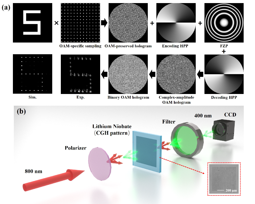
The encoding process of the OAM holography is shown in Fig. 1a. The target image is firstly sampled according to the spatial frequency of the selected encoding helical phase (see Supplementary Note 2). Then, the Gerchberg-Saxton (GS) algorithm is utilized to obtain the OAM-preserved hologram. To construct an OAM-selected hologram, a helical phase plate (HPP) with is encoded onto the OAM-preserved hologram. According to the nonlinear OAM conservation law[19] and nonlinear OAM-matching condition[20] , where is the topological charge carried by the incident fundamental beam. The target image can be clearly reconstructed only when an incident OAM beam with is used and the reconstructed image consists of pixels that feature Gaussian mode showing high-intensity distribution. On the contrary, if a mismatched OAM beam is incident, each pixel maintains the vortex characteristics and exhibits a lower intensity distribution, which can be regarded as background noise. In this work, a decoding HPP with is directly superimposed onto the hologram instead of the OAM beam incidence.
In the OAM holography, the electric field on the hologram plane and that on the image plane form a Fourier pair. Direct superposition of a FZP on a Fourier hologram will generate a single-plane Fresnel hologram (see Supplementary Note 3), where the focal length of the FZP can be used to translate the image to any distance[10] controllably. Notably, this flexibility is further exemplified by our ability to superimpose Fresnel zone plates with different focal lengths in various OAM channels, thereby projecting different target images onto planes at distinct depths, namely, the three-dimensional multi-plane OAM holography. Meanwhile, the traditional Fourier transform lens structure can be omitted, which greatly simplifies the optical configuration. The phase function of FZP can be written as:
| (1) |
where represents the Cartesian coordinates in the holographic plane, is the wavevector and represents the focal length. So the final complex-amplitude distribution of an OAM multiplexed hologram can be described mathematically as:
| (2) |
where n is the total OAM channel number, is the complex-amplitude distribution of the sampled target image obtained by GS algorithm encoded on the j-th OAM channel, is the phase distribution of the j-th encoding HPP, denotes the phase function of the FZP superimposed on the j-th OAM channel and is the phase distribution of the decoding HPP. It is worth noting that the depth controllability is achieved by loading different FZP phases onto different OAM channels. It should be emphasized that the size of the reconstructed target image is directly related to the focal length of the FZP. The larger the focal length, the larger the size of the image. Therefore, to achieve a realistic restoration of a three-dimensional object, the images of each plane need to be scaled accordingly in advance (Supplementary Note 4).
Finally, we choose a suitable way to encode the complex-amplitude field onto the holographic plane. Considering that we use the femtosecond laser to erase the nonlinear coefficient of the lithium niobate crystal which results in two states corresponding to the actual laser-nonirradiated area and laser-irradiated area, the binary Fresnel CGH was selected in our experiments (see Methods).
Notably, both the FZPs and the binarization process in the encoding process are wavelength-dependent. Therefore, we adopted a configuration where the beam was first frequency-doubled and then modulated, with the design of CGHs specifically tailored for the SH beam. Under the irradiation from the opposite direction, the target image can not be clearly reconstructed(see Supplementary Note 5), enabling nonreciprocal information processing.
To validate the effectiveness of this encoding method, the letter S was encoded with a HPP with and a FZP with . When a decoding HPP with was superimposed onto the hologram, a distinct SH pattern emerged at the corresponding distance with Gaussian-spot pixels under the condition of Gaussian beam incidence, as shown in Figure 1a. The slight difference between the experiment and theoretical simulation is the imperfection of the produced ferroelectric domain structure and the unavoidable random structure errors.
OAM-multiplexing holography at the same imaging plane
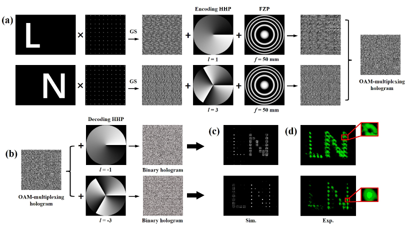
The more pronounced difference between the OAM-matching and OAM-mismatching can be demonstrated by constructing an OAM-multiplexing hologram. As can be seen from Figure 2a, letters L and N, namely the abbreviation for lithium niobate crystal, were encoded separately into two OAM channels, i.e. and , while superimposing identical FZPs with projects them onto the same imaging plane. The decoding process can be performed by superimposing corresponding decoding HPP onto the OAM-multiplexing hologram as shown in Figure 2b. Figure 2c and (d) show the simulation and experimental results, respectively. It is clear that the decoded target image consisted of Gaussian-shaped pixels showing high intensity, corresponding to the OAM-matching condition being satisfied. Due to the OAM mismatching, the other letter had donut-shaped pixels and relatively low intensity, which can be regarded as background noise and can be further removed through post-processing.
OAM-multiplexing holography for 3D multi-plane imaging
Suffering from strong crosstalk and varying DoFs between adjacent planes, it is challenging for traditional 3D holographic imaging techniques to achieve large-capacity and high-fidelity 3D information storage. By leveraging the orthogonality of OAM modes, crosstalk can be significantly reduced, especially since the proposed encryption method now enables precise and independent control over the imaging distances of each OAM channel. Additionally, the intervals between adjacent imaging planes are no longer constrained by the DoFs.
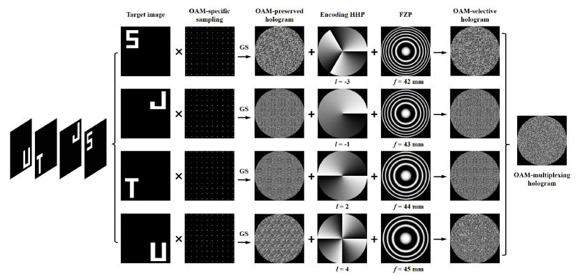
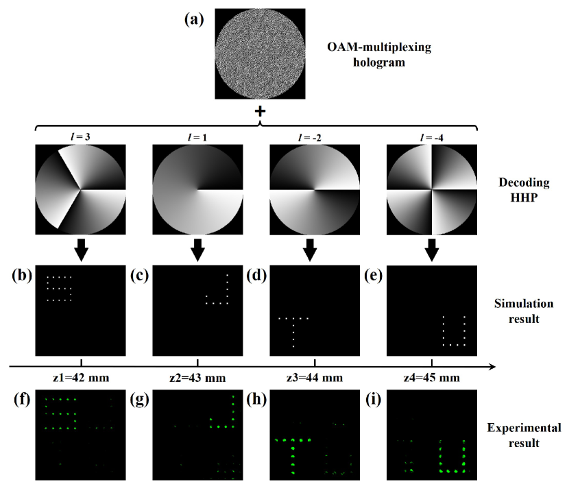
To characterize the 3D reconstruction performance of the proposed OAM holography, we chose multi-plane images of the letters "SJTU" as our 3D object model. As is illustrated in Figure 3, the four letters are divided into four layers which are positioned at different distances from the hologram (, , , ). After performing the GS algorithm, they were separately encoded into four different OAM channels (, , , ) and superimposed with corresponding FZPs for independent projection. The OAM-multiplexing hologram was obtained by superposing four DC-OAM-selective holograms. The decoding process is shown in Figure 4a. To reconstruct a specific target image, correct decoding HHP should be superimposed onto the OAM-multiplexing hologram. The numerical reconstructions under the Gaussian beam incidence at four different depth planes are shown in Figure 4b-e and the corresponding experimental reconstruction results are shown in Figure 4f-i. After applying a mode-selective aperture array in post-processing of the reconstructed holographic images, most of the OAM-mismatching target images were filtered. As we can see, the expected letters appeared at pre-designed distances. Due to inevitable discrepancies between the actual fabricated structures and the designed CGH pattern, the interference between OAM modes in adjacent pixels, termed as adjacent pixel interference (API), is unavoidable. Consequently, high-intensity pixels comparable to those in the signal regions appear in the non-signal areas during experiments, and these pixels cannot be filtered out.
Discussion
The imaging distances and the number of target images selected in this experiment are merely exemplary. In practice, smaller distance intervals and a greater number of images can be selected. Both of the transverse resolution and longitudinal resolution, or equivalently the capacity, are constrained by the OAM sampling condition and the numerical aperture of the CCD camera. A larger number of target images necessitates a larger sampling constant. This implies that the target images need to be magnified and a camera with a larger numerical aperture should be used; otherwise, the resolution of the images will degrade, potentially leading to distortion. If our holograms are loaded onto a spatial light modulator and a temporal multiplexing method is employed[21], this issue can be mitigated. A more detailed discussion of the capacity and resolution is provided in Supplementary Note 6. Meanwhile, our encryption method is compatible with other enhanced OAM holography techniques[22, 23, 24, 25, 26, 27, 28, 21], and their integration allows us to further enhance the capacity and resolution of three-dimensional holographic imaging.
In conclusion, we have proposed the concept of 3D OAM nonlinear holography and employed femtosecond laser micromachining technique to fabricate CGH pattern onto the lithium niobate crystal. Our approach utilizes superimposed FZPs in CGH replacing the Fourier transform lens used in the traditional OAM holography, enabling us to flexibly control over imaging distance. Meanwhile, the optical configuration is greatly simplified. Moreover, we constructed OAM-multiplexing holograms to independently project images that loaded in different OAM channels to distinct positions, thereby achieving low-crosstalk 3D multi-plane holographic imaging. Experimental verification has demonstrated the feasibility of 3D OAM nonlinear holography. It is worth mentioning that the proposed OAM holographic encoding strategy represents a universal approach compatible with the majority of OAM holography techniques, holding great promise for applications in various field including 3D display and optical manipulation.
Method
Binarization of the Complex-amplitude OAM Hologram
To record the information of the complex-amplitude OAM hologram onto the lithium niobate crystal, the method of binary interference CGH is used. Through the interference of the object wave and the planar reference wave , where and are the amplitude and phase term of the complex amplitude on the holographic plane, and are the amplitude and the carrier frequency respectively, we first obtain the transmittance function of the hologram:
| (3) |
The bright fringes equation of the hologram can be obtained as:
| (4) |
where represents the serial number of the bright fringes, .By solving the position of each bright fringe and opening a thin slit, a binary transmission grating is formed, that is, the phase of the object wave is encoded. The encoding of the amplitude is obtained by introducing an offset to modulate the width of the bright fringes[29], where and the amplitude takes the normalized value. This encoding method is widely used in standard wavefront generation and interference detection[30, 31]. Then, the final interference binary CGH is represented as follows:
| (5) |
Fabrication of CGH by Femtosecond Laser Erasure
The CGH is fabricated using a NIR laser working at wavelength, reputation rate, and pulse width (Coherent Legend Elite). A MgO-doped LiNbO3 crystal with a thickness of is used as a sample which is mounted on the computer-controlled XYZ translation stage with a resolution of . An objective lens with a numerical aperture of (Nikon CFI TU Plan Fluor BD) is applied to focus the laser pulse onto the surface of the crystal. The moving speed is and the moving direction is perpendicular to the laser beam. In our experiment, a single pulse of about is used. Controlled by the computer program, the ferroelectric domain of the crystal is selectively erased corresponding to the dark area of the CGHs. While the non-irradiated points correspond to the white area of the CGHs. The physical mechanism of the ferroelectric domain erasing process can be understood in that the crystallinity is reduced through laser irradiation[32].We fabricated the CGH patterns with pixels, where each pixel has a size approximately at . The fabricated CGHs were written within an area of and the total processing time is .
Experimental Set-up
Figure 1b shows the optical holographic imaging system. The fundamental frequency (FF) beam with a wavelength of is used for image reconstruction. A linear polarizer was utilized to adjust the polarization of the FF beam. Afterward, an ordinary polarized laser beam was irradiated onto the sample. Given that the CGH pattern was inscribed on the surface of the LiNbO3 crystal, we arranged the sample such that the FF beam initially traversed the unmodulated LiNbO3 crystal, where the second harmonic (SH) beam was generated at the wavelength of . Subsequently, the SH beam was modulated by the CGH and projected to the corresponding depth for imaging. Before the CCD camera, a filter was used to separate the FF and SH beams.
Acknowledgement
This work was supported by the National Natural Science Foundation of China (Grant Nos. 12134009), and Shanghai Jiao Tong University (SJTU) (Grant No. 21X010200828).
Author contributions
Feiyang Shen prepared the manuscript in discussion with all authors. Feiyang Shen and Yuping Chen designed the holographic method and analyzed the data. Feiyang Shen and Weiwen Fan fabricated the hologram onto the lithium niobate crystal and performed the experiments. Feiyang Shen, Yuping Chen and Yong Zhang revised the manuscript. Yuping Chen supervised the project.
Conflict of interest
The authors declare no competing interests.
References
- [1] Rainer G Dorsch, Adolf W Lohmann, and Stefan Sinzinger. Fresnel ping-pong algorithm for two-plane computer-generated hologram display. Applied optics, 33(5):869–875, 1994.
- [2] Lingling Huang, Xianzhong Chen, Holger Mühlenbernd, Hao Zhang, Shumei Chen, Benfeng Bai, Qiaofeng Tan, Guofan Jin, Kok-Wai Cheah, Cheng-Wei Qiu, et al. Three-dimensional optical holography using a plasmonic metasurface. Nature communications, 4(1):2808, 2013.
- [3] Ruidan Kang, Juan Liu, Gaolei Xue, Xin Li, Dapu Pi, and Yongtian Wang. Curved multiplexing computer-generated hologram for 3d holographic display. Optics Express, 27(10):14369–14380, 2019.
- [4] Monjurul Meem, Apratim Majumder, and Rajesh Menon. Multi-plane, multi-band image projection via broadband diffractive optics. Applied Optics, 59(1):38–44, 2020.
- [5] Maria Manousidaki, Dimitrios G Papazoglou, Maria Farsari, and Stelios Tzortzakis. 3d holographic light shaping for advanced multiphoton polymerization. Optics Letters, 45(1):85–88, 2020.
- [6] Bing Zhu, Haigang Liu, Yuping Chen, and Xianfeng Chen. High conversion efficiency second-harmonic beam shaping via amplitude-type nonlinear photonic crystals. Optics Letters, 45(1):220–223, 2020.
- [7] Bing Zhu, Haigang Liu, Xiongshuo Yan, Yuping Chen, Xianfeng Chen, et al. Second-harmonic computer-generated holographic imaging through monolithic lithium niobate crystal by femtosecond laser micromachining. Optics Letters, 45(15):4132–4135, 2020.
- [8] Pengcheng Chen, Xiaoyi Xu, Tianxin Wang, Chao Zhou, Dunzhao Wei, Jianan Ma, Junjie Guo, Xuejing Cui, Xiaoyan Cheng, Chenzhu Xie, et al. Laser nanoprinting of 3d nonlinear holograms beyond 25000 pixels-per-inch for inter-wavelength-band information processing. Nature Communications, 14(1):5523, 2023.
- [9] Honghuan Tu, Tingge Yuan, Zhiwei Wei, Yuping Chen, and Xianfeng Chen. Fabrication of 3d computer-generated hologram inside glass by femtosecond laser direct writing. Optical Materials, 135:113228, 2023.
- [10] Ghaith Makey, Özgün Yavuz, Denizhan K Kesim, Ahmet Turnalı, Parviz Elahi, Serim Ilday, Onur Tokel, and F Ömer Ilday. Breaking crosstalk limits to dynamic holography using orthogonality of high-dimensional random vectors. Nature photonics, 13(4):251–256, 2019.
- [11] Xinyuan Fang, Xiaonan Hu, Baoli Li, Hang Su, Ke Cheng, Haitao Luan, and Min Gu. Orbital angular momentum-mediated machine learning for high-accuracy mode-feature encoding. Light: Science & Applications, 13(1):49, 2024.
- [12] Chenhao Wan, Qian Cao, Jian Chen, Andy Chong, and Qiwen Zhan. Toroidal vortices of light. Nature Photonics, 16(7):519–522, 2022.
- [13] Xinyuan Fang, Haoran Ren, and Min Gu. Orbital angular momentum holography for high-security encryption. Nature Photonics, 14(2):102–108, 2020.
- [14] Xiao-Jie Wang, Hong-Hua Fang, Zhen-Ze Li, Dan Wang, and Hong-Bo Sun. Laser manufacturing of spatial resolution approaching quantum limit. Light: Science & Applications, 13(1):6, 2024.
- [15] Yuying Wang, Lijing Zhong, Kuen Yao Lau, Xuhu Han, Yi Yang, Jiacheng Hu, Sergei Firstov, Zhi Chen, Zhijun Ma, Limin Tong, et al. Precise mode control of laser-written waveguides for broadband, low-dispersion 3d integrated optics. Light: Science & Applications, 13(1):130, 2024.
- [16] Zhen-Ze Li, Lei Wang, Hua Fan, Yan-Hao Yu, Qi-Dai Chen, Saulius Juodkazis, and Hong-Bo Sun. O-fib: far-field-induced near-field breakdown for direct nanowriting in an atmospheric environment. Light: Science & Applications, 9(1):41, 2020.
- [17] Shan Liu, Leszek Mateusz Mazur, Wieslaw Krolikowski, and Yan Sheng. Nonlinear volume holography in 3d nonlinear photonic crystals. Laser & Photonics Reviews, 14(11):2000224, 2020.
- [18] Han Zhu, Lingrui Chu, Weijie Liu, Saulius Juodkazis, and Feng Chen. Ultrafast laser-induced plasmonic modulation of optical properties of dielectrics at high resolution. Advanced Optical Materials, 11(22):2300929, 2023.
- [19] Xiaopeng Hu, Yong Zhang, and Shining Zhu. Nonlinear beam shaping in domain engineered ferroelectric crystals. Advanced Materials, 32(27):1903775, 2020.
- [20] Xinyuan Fang, Huijun Wang, Haocheng Yang, Zhilin Ye, Yongmei Wang, Yong Zhang, Xiaopeng Hu, Shining Zhu, and Min Xiao. Multichannel nonlinear holography in a two-dimensional nonlinear photonic crystal. Physical Review A, 102(4):043506, 2020.
- [21] Zijian Shi, Zhensong Wan, Ziyu Zhan, Kaige Liu, Qiang Liu, and Xing Fu. Super-resolution orbital angular momentum holography. Nature Communications, 14(1):1869, 2023.
- [22] Pengyu Cheng, Sujuan Huang, and Cheng Yan. Ellipticity-encrypted orbital angular momentum multiplexed holography. JOSA A, 38(12):1875–1883, 2021.
- [23] Guoxuan Zhu, Zhiyong Bai, Jiayan Chen, Churou Huang, Luping Wu, Cailing Fu, and Yiping Wang. Ultra-dense perfect optical orbital angular momentum multiplexed holography. Optics Express, 29(18):28452–28460, 2021.
- [24] Feili Wang, Xiangchao Zhang, He Yuan, Rui Xiong, and Xiangqian Jiang. Enhancing the information capacity with modulated orbital angular momentum holography. IEEE Photonics Journal, 14(1):1–5, 2022.
- [25] Feili Wang, Xiangchao Zhang, Rui Xiong, Xinyang Ma, and Xiangqian Jiang. Angular multiplexation of partial helical phase modes in orbital angular momentum holography. Optics Express, 30(7):11110–11119, 2022.
- [26] Fajing Li, Shouping Nie, Jun Ma, and Caojin Yuan. Multiple-dimensional multiplexed holography based on modulated chiro-optical fields. Optics Express, 30(23):41567–41579, 2022.
- [27] Fajing Li, Hao Ding, Shouping Nie, Jun Ma, and Caojin Yuan. Multiple-image encryption using phase jump gradient factors-based oam multiplexing holography. Optics and Lasers in Engineering, 160:107303, 2023.
- [28] Nian Zhang, Baoxing Xiong, Xiang Zhang, and Xiao Yuan. Multiparameter encrypted orbital angular momentum multiplexed holography based on multiramp helicoconical beams. Advanced Photonics Nexus, 2(3):036013–036013, 2023.
- [29] Wai-Hon Lee. Binary synthetic holograms. Applied optics, 13(7):1677–1682, 1974.
- [30] JC Wyant and VP Bennett. Using computer generated holograms to test aspheric wavefronts. Applied Optics, 11(12):2833–2839, 1972.
- [31] James H Burge. Applications of computer-generated holograms for interferometric measurement of large aspheric optics. In International Conference on Optical Fabrication and Testing, volume 2576, pages 258–269. SPIE, 1995.
- [32] Dunzhao Wei, Chaowei Wang, Huijun Wang, Xiaopeng Hu, Dan Wei, Xinyuan Fang, Yong Zhang, Dong Wu, Yanlei Hu, Jiawen Li, et al. Experimental demonstration of a three-dimensional lithium niobate nonlinear photonic crystal. Nature Photonics, 12(10):596–600, 2018.