Dispersion Characteristics of a Glide-Symmetric Square Patch Metamaterial with Giant Anisotropy
Abstract
This paper investigates the dispersion characteristics of a highly anisotropic metamaterial comprised of metal square patches arranged in a glide symmetry pattern and submerged in vacuum. Theoretical formulas are proposed to describe the electromagnetic tensors of a corresponding uniaxial effective medium with dielectric and magnetic responses. In addition, this work employs theoretical analysis and numerical simulations to examine the interaction between the metamaterial and electromagnetic waves across a broad spectral range. Band diagrams and isofrequency contours show good agreement between theoretical and numerical results for low frequencies and certain directions of propagation at higher frequencies. The ease of designing the metamaterial structure for various applications is facilitated by the derived theoretical formulas, which enable accurate prediction of the electromagnetic response across a wide range of frequencies based on geometric parameters.
I Introduction
Metamaterials are artificial materials with electromagnetic properties beyond those found in natural materials. One particular class of metamaterial exhibits anisotropy, meaning that material responses depend on the direction of propagation of electromagnetic waves. Studies have revealed exotic electromagnetic properties in anisotropic metamaterials such as negative-refraction [1], near-zero parameters [2], and manipulation of polarization states in reflection [3].
Symmetries, together with an adequate selection of parameters and constituents of metamaterial structures, enable the design of materials with particular electromagnetic wave propagation properties. A symmetry that has been exploited to attain exceptional electromagnetic responses is a higher symmetry known as glide symmetry. Structures with gliding symmetry are those built by reflecting and translating building blocks. It has been shown that with an adequate selection of parameters, metamaterials based on glide symmetry allow to reduce the dispersion [4, 5] and increase the effective refractive index [6, 7].
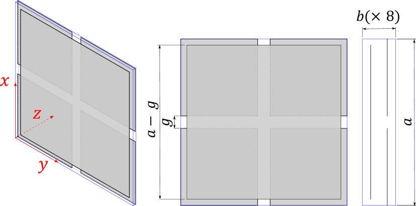
A unique anisotropic metamaterial based on glide symmetry consist of an array of square metal patches that are repeated with a period along the directions parallel to the patches (transverse directions), and a period along the direction perpendicular to the patches (axial direction), as shown Fig. 1 for a supercell of the structure. With a much larger period along the transversal directions compared to the axial direction (), a high dielectric permittivity uniaxial material is obtained [8, 9]. Taking advantage of the unique characteristics of the metamaterial, it has been proposed as a component of practical applications related with microwave engineering [10, 11] and magnetic resonance imaging [12].
Effective medium models have been proposed to study the dispersion characteristics of the square patch metamaterial along the axial direction, considering a uniform electric charge across the metal patches [8]. Furthermore, analytical models have been put forth to realize the scattering parameters of plane waves impinging structures based on layers with non aligned metal patches [13]. However, the magnetic behavior of the structure and the frequency range of validity for existing effective medium models are not well established yet. In this article, we present theoretical formulas that predict the dispersion properties of the square patch metamaterial depending on the geometrical parameters of the structure. The theoretical results are compared with numerical ones to check the scope of validity of the proposed effective medium. Dispersion diagrams and isofrequency contours of propagating modes supported by the structure are analyzed. In addition, the electromagnetic parameters are theoretically and numerically retrieved for low frequencies. Our results show that the effective medium approach is valid for low frequencies and for high frequencies along certain directions of propagation.
II Theory
The theoretical model is based on a quasi-static approach including both electrostatic and magnetostatic studies [14]. For simplicity, the host medium is considered as vacuum, and the metallic patches are considered made of Perfect Electric Conductor (PEC). Bianisotropic effects are discarded because of the presence of a center of symmetry in the unit cell and non-linear effects are not considered. Consequently, linear constitutive relations are assumed. Moreover, due to mirror symmetries of the unit cell, both the permittivity and permeability tensors are diagonal. Therefore, the constitutive relations can be written as,
| (1) |
| (2) |
in which the unknown parameters are the relative transverse permittivity () and the relative axial permeability (). For identifying the components of the electromagnetic tensors it is considered that the field components , , and do not interact with the conducting patches, then . In addition, the structure is symmetric under a rotation around the -axis, implying .
II.1 Transverse relative permittivity
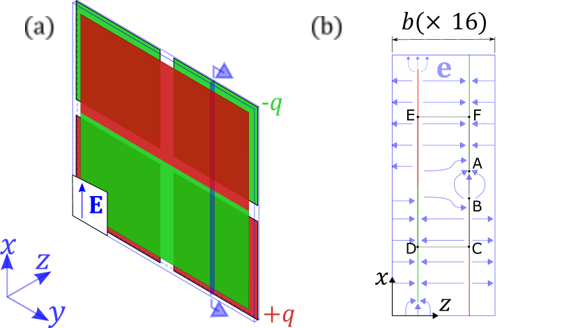
It is assumed that both the macroscopic electric field and the polarization are oriented along the -axis, considering that the macroscopic electric field is understood as the average electric field along the unit cell. The electric responses within the unit cell due to this -oriented are illustrated in Fig. 2. As a consequence, from the usual constitutive relation connecting the electric vectors,
| (3) |
the transverse permittivity can be obtained,
| (4) |
Therefore, it is needed to analyze and to estimate the transverse permittivity.
To analyze , the microscopic electric field is used, which is the electric field in each point of the unit cell (see Fig. 2b). Following a vertical line passing through the points F, A, B, and C marked in Fig. 2b, it is noted that due to the boundary conditions in PEC, it is possible to obtain a non-zero electric field only in the gap of vacuum, so that,
| (5) |
Conversely, applying Faraday’s Law in the quasi-static regime along the closed integration path ABCDEF depicted in Fig. 2b,
| (7) |
where is the surface density in the half of a patch.
The polarization () is obtained by calculating the dipole moment due to two quarters of patches divided by the quarter of volume of the supercell since there are two patches in the cell,
| (8) |
where represents the overlapping area between quarters of patches in adjacent layers. Substituting Eqs. (7), and (8) into Eq. (4) yields,
| (9) |
Including edge effects of the electric charge, the polarization is corrected as,
| (10) |
where the last term comes from the charge density along the edges of quarter of patches. is a linear charge density, which is derived in Supplemental Material, . Therefore, substituting Eqs. (7) and (10) into Eq. (4),
| (11) |
II.2 Axial relative permeability
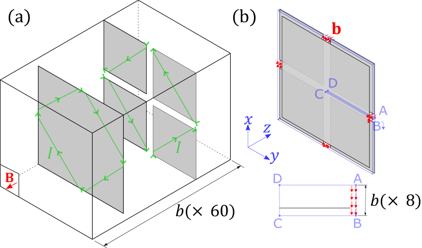
It is assumed that both the macroscopic magnetic flux density and the magnetization are oriented along the -axis, considering that the macroscopic magnetic flux density is understood as the average magnetic flux density along the unit cell. The magnetic responses within the unit cell due to this -oriented are illustrated in Fig. 3. Consequently, from the usual constitutive relation connecting the magnetic vectors,
| (12) |
the axial permeability can be obtained,
| (13) |
Once and are identified, the axial permeability can be estimated. To analyze , the microscopic magnetic flux density is used, which is the magnetic flux density in each point of the unit cell. According to the boundary conditions for PEC, should be negligible in the regions bounded by parallel plates since they are tightly packed and over the PEC. On the other hand, along the canals formed by the crosses of orthogonal slots, see Fig. 3b. Therefore, applying Ampere’s Law in the quasi-static regime along the closed integration path ABCD depicted in Fig. 3b results in,
| (14) |
Equating the magnetic flux in the unit cell across the -plane from the macroscopic and microscopic points of view and using Eq. (14),
| (15) |
II.3 Dispersion relations
Using Maxwell’s equations and considering plane wave propagation, the dispersion equations for the modes supported by the effective uniaxial medium are derived in accordance with [15],
| (20) |
| (21) |
When waves propagate perpendicular to the metal patches, the material’s behavior is primarily governed by the transverse permittivity (). However, for grazing incidence, the transverse permeability () also becomes a significant factor. This type of metamaterial belongs to the class of uniaxial dielectric-magnetic media, established in the [16, 17]. Recent studies have proposed the use of uniaxial dielectric-magnetic materials as a foundation for realizing angle-selective surfaces [18] and impedance matching layers [19].
III Numerical investigation
To illustrate the highly anisotropic response of the studied structure, we consider the following geometrical parameters: , and . Substituting these values into Eqs. (11) and (19) yields in a relative transversal permittivity of and a relative axial permeability of .
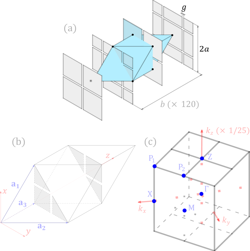
The periodic nature of the square patch metamaterial reassembles a body-centered tetragonal crystal system [20]. Therefore, a supercell of the structure consists in translation vectors , , and containing two patches, as illustrates Fig. 1. In this study, we consider a primitive unit cell to numerically analyze the dispersion of the square patch metamaterial, as shown Fig. 4b. The election of a primitive unit cell to study a metamaterial is important to completely describe the dispersion characteristics of the structure and avoid redundant information, as was shown in [21], [22]. In addition, the selected unit cell fully exploits the glide symmetry of the structure, considering that each node in the cell is connected to adjacent points in different planes that are translated along both and directions (see Fig. 4a). Consequently, the components of the translation vectors of the primitive unit cell are given by,
| (22) |
The Brillouin zone corresponding to the primitive unit cell, with the shape of a dodecahedron, is illustrated in Fig. 4c. The dispersion characteristics of the square patch metamaterial are numerically studied using the commercial software COMSOL MULTIPHYSICS, implementing periodic boundary conditions to the primitive unit cell, with spatial dependence.
III.1 Dispersion relations
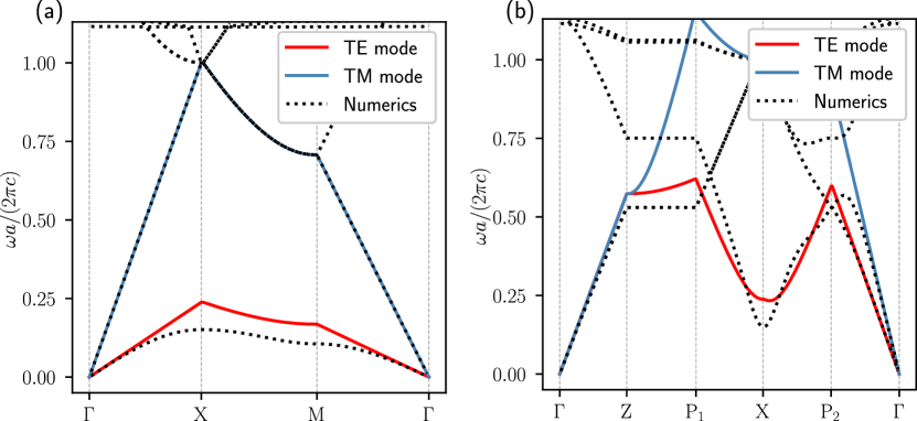
The dispersion relations are analyzed along paths involving the high symmetric points illustrated in Fig 4c. As a result, Fig. 5 illustrates theoretical and computational dispersion diagrams, in which TE mode and TM mode correspond to Eqs. (20) and (21), respectively.
The dispersion relations along path are illustrated in Fig. 5a. The TM mode is characterized by a lack of interaction with the metal patches, resulting in a perfect degree of similarity with numerical results and resembling the propagation of light in vacuum, as shown Eq. (21) with . Conversely, the TE mode demonstrates good agreement for low frequencies, with a relative error of observed at the point. The agreement between theoretical and computational results starts to degrade for regions close to the edges of the first Brillouin zone, which is a typical limitation of effective medium models [23]. In this work, the relative error is calculated by comparing simulation results relative to theoretical predictions.
Including points with , Fig. 5b illustrates the dispersion relations along path . There is a notable concurrence between theoretical and numerical results for both TE and TM modes below . In addition, along direction, which is the direction exhibiting a giant relative permittivity, the higher the frequency, the higher the relative error, with a maximum value of observed at point.
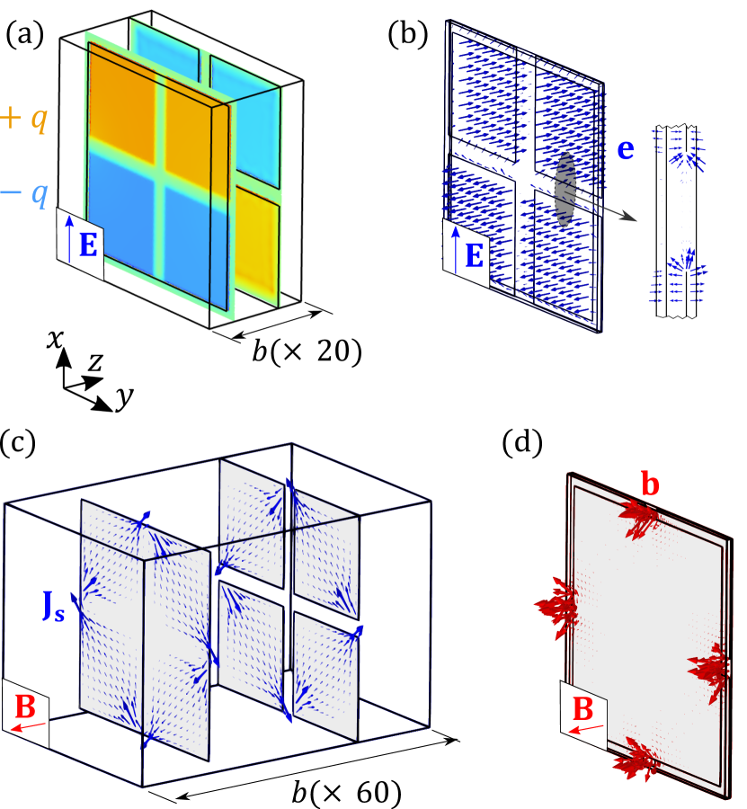
The agreement between theoretical and numerical results for the dispersion relations is further supported by the computational validation of the assumed electric and magnetic responses of the metamaterial. To this end, plane waves with frequency are impinged upon a supercell of the structure, as shown in Fig. 6. The results corroborate the theoretical electric responses in Fig. 2 and the theoretical magnetic responses in Fig. 3.
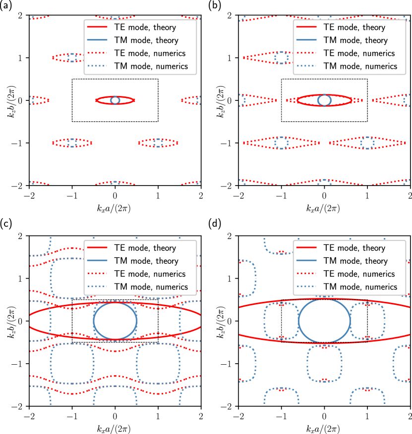
Following the dispersion analysis of the structure, isofrequency contours in plane are illustrated in Fig. 7, in which the black dotted line indicates the edges of the first Brillouin zone. At low frequencies, i.e. , Fig. 7a shows a perfect agreement between theory and simulations for both TE and TM modes. However, this agreement weakens at higher frequencies. At , illustrated in Fig. 7b, it is noted that there is a perfect agreement for the TM mode, but the TE mode shows a discrepancy between theoretical and numerical results along directions close to -direction. At , the agreement for the TE mode is limited to -direction, and the agreement for TM mode is limited to - and - directions, see Fig. 7c. Finally, Fig. 7d shows a significant discrepancy at , indicating a breakdown of the model’s validity due to a topological transition in the isofrequency contours.
III.2 Electromagnetic parameters dependence on geometry
In order to investigate the performance of the model under variations of the gap () between metallic patches, Fig. 8 shows theoretical and simulations results for the effective permittivity and permeability of the structure as a function of when . The theoretical results are obtained directly from equations (9) and (17) for Model 1, and from equations (11) and (19) for Model 2, which include edge effects. On the other hand, numerical results are obtained from the dispersion along -direction to retrieve first the transversal permittivity, considering that a linear dispersion is evidenced in Fig. 5b (path ) at low frequencies,
| (23) |
Then, the axial permeability is retrieved from the dispersion along -direction, considering a linear dispersion at low frequencies (see Fig. 5a , path ),
| (24) |
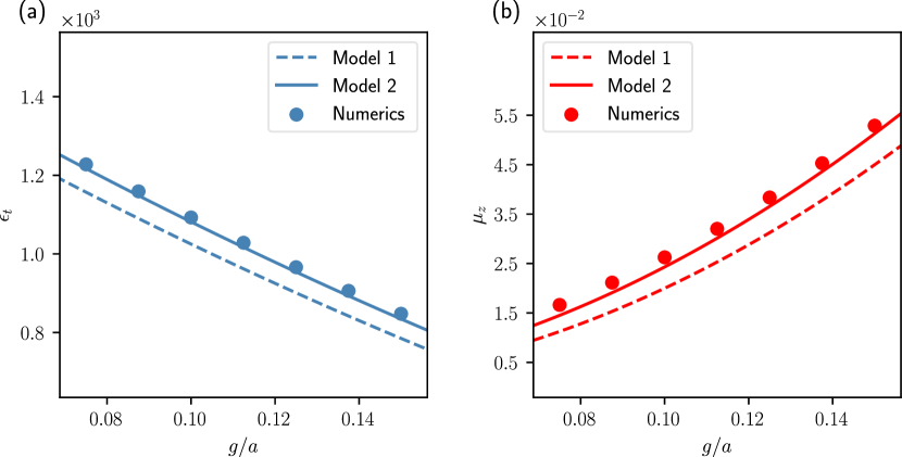
Fig. 8a illustrates the effective relative permittivity (), showing an advantageous range of values from approximately to for the interval . Similarly, Fig. 8b demonstrates a range of effective relative permeability values () from approximately to within the same interval. It is worth noting that Model 2 exhibits improved agreement with the numerical results compared to Model 1. A smaller ratio weakens the assumption of an exponential decay for the edge effect (see Supplemental Material), leading to a larger relative error in the calculated magnetic permeability.
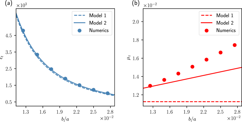
Figure 9 presents theoretical and simulation results, obtained using the aforementioned methodology, for the effective relative permittivity and effective relative permeability of the structure as a function of when . Within the domain a wide range of transversal permittivity values are achieved in Fig. 9a (from approximately to ). In contrast, Fig. 9b shows minimal variation in permeability within the same domain, with values ranging from approximately to . Notably, Model 2 exhibits significantly improved agreement with the numerical results compared to Model 1. When the ratio increases, the agreement of the theoretical models decreases with respect to numerical results since the assumption of tightly packet patches weakens.
IV Conclusions
A theoretical and computational study was conducted to elucidate the dispersion characteristics of the square patch metamaterial. Our findings reveal that the structure emulates the behavior of a uniaxial dielectric magnetic material at low frequencies. Furthermore, we have established accurate and straightforward theoretical formulas for estimating the key electromagnetic parameters of these metamaterials. These formulas unveil the critical dependence of both the transversal permittivity and the axial permeability on the spatial periods and the gaps between the constituent patches. Moreover, the derived expressions predict that the square patch metamaterial not only exhibits an exceptionally large transverse permittivity but also possesses an extremely small axial permeability.
Comparing theoretical results with computational simulations based on a body-centered tetragonal representation of the square patch metamaterial, the theoretical model demonstrates its efficacy in predicting the dispersion characteristics up to approximately coinciding with the onset of topological transitions. Notably, good agreement is observed between theory and simulations, with a relative error of at point and at point. Furthermore, the theoretical formulas allow for the prediction of the relative transverse permittivity within a range of 800 to 4500, and the relative permeability within a range of approximately 0.010 to 0.050. These findings highlight the potential of the developed theoretical model for guiding the design of square patch metamaterials with tailored electromagnetic properties. Further research could explore the application of this model to similar structures with even more degrees of freedom, such as glide-symmetric structures with metallic objects with shapes different to the square shape, and investigate the influence of fabrication tolerances on the predicted properties. This would significantly advance the development of practical metamaterial devices, enabling functionalities such as angle-selective surfaces with even finer control over electromagnetic wave propagation or impedance matching layers with broader bandwidths.
References
- Poddubny et al. [2013] A. Poddubny, I. Iorsh, P. Belov, and Y. Kivshar, Nature Photonics 7, 948 (2013) .
- Zhang and Wu [2015] X. Zhang and Y. Wu, Scientific Reports 5, 7892 (2015).
- Hao et al. [2007] J. Hao, Y. Yuan, L. Ran, T. Jiang, J. A. Kong, C. T. Chan, and L. Zhou, Physical Review Letters 99, 063908 (2007).
- Quevedo-Teruel et al. [2020] O. Quevedo-Teruel, G. Valerio, Z. Sipus, and E. Rajo-Iglesias, IEEE Microwave Magazine 21, 36 (2020).
- Quevedo-Teruel et al. [2021] O. Quevedo-Teruel, Q. Chen, F. Mesa, N. J. Fonseca, and G. Valerio, IEEE Journal of Microwaves 1, 457 (2021).
- Ebrahimpouri and Quevedo-Teruel [2019] M. Ebrahimpouri and O. Quevedo-Teruel, IEEE Antennas and Wireless Propagation Letters 18, 1547 (2019).
- Arnberg et al. [2020] P. Arnberg, O. Barreira Petersson, O. Zetterstrom, F. Ghasemifard, and O. Quevedo-Teruel, Applied Sciences 10, 3216 (2020).
- Chang et al. [2016] T. Chang, J. U. Kim, S. K. Kang, H. Kim, D. K. Kim, Y.-H. Lee, and J. Shin, Nature Communications 7, 12661 (2016).
- Barzegar-Parizi and Rejaei [2015] S. Barzegar-Parizi and B. Rejaei, IET Microwaves, Antennas & Propagation 9, 1287 (2015).
- Ma et al. [2008] Y. Ma, B. Rejaei, and Y. Zhuang, IEEE Microwave and Wireless Components Letters 18, 431 (2008).
- Takahagi and Sano [2011] K. Takahagi and E. Sano, IEEE Transactions on Antennas and Propagation 59, 3624 (2011).
- Vorobyev et al. [2020] V. Vorobyev, A. Shchelokova, I. Zivkovic, A. Slobozhanyuk, J. D. Baena, J. P. del Risco, R. Abdeddaim, A. Webb, and S. Glybovski, Journal of Magnetic Resonance 320, 106835 (2020).
- Cavallo and Felita [2017] D. Cavallo and C. Felita, IEEE Transactions on Antennas and Propagation 65, 5303 (2017).
- Baena et al. [2020] J. D. Baena, J. P. del Risco, and A. C. Escobar, in 2020 Fourteenth International Congress on Artificial Materials for Novel Wave Phenomena (Metamaterials) (2020) pp. 367–369.
- Depine et al. [2006] R. A. Depine, M. E. Inchaussandague, and A. Lakhtakia, JOSA A 23, 949 (2006).
- Lakhtakia and Weiglhofer [1997] A. Lakhtakia and W. S. Weiglhofer, International Journal of Applied Electromagnetics and Mechanics 8, 167 (1997).
- Weiglhofer and Lakhtakia [1996] W. Weiglhofer and A. Lakhtakia, International journal of infrared and millimeter waves 17, 1365 (1996).
- Huang and Shen [2020] H. Huang and Z. Shen, IEEE Antennas and Wireless Propagation Letters 19, 2457 (2020).
- He and Eleftheriades [2018] Y. He and G. V. Eleftheriades, Phys. Rev. B 98, 205404 (2018).
- Mehl et al. [2017] M. J. Mehl, D. Hicks, C. Toher, O. Levy, R. M. Hanson, G. Hart, and S. Curtarolo, Computational Materials Science 136, S1 (2017).
- Sakhno et al. [2021] D. Sakhno, E. Koreshin, and P. A. Belov, Physical Review B 104, L100304 (2021).
- Yang et al. [2023] S. Yang, O. Zetterstrom, F. Mesa, and O. Quevedo-Teruel, IEEE Journal of Microwaves (2023).
- Belov and Simovski [2005] P. A. Belov and C. R. Simovski, Phys. Rev. E 72, 026615 (2005).