Pure kinetic inductance coupling for cQED with flux qubits
Abstract
We demonstrate a qubit-readout architecture where the dispersive coupling is entirely mediated by a kinetic inductance. This allows us to engineer the dispersive shift of the readout resonator independent of the qubit and resonator capacitances. We validate the pure kinetic coupling concept and demonstrate various generalized flux qubit regimes from plasmon to fluxon, with dispersive shifts ranging from 60 kHz to 2 MHz at the half-flux quantum sweet spot. We achieve readout performances comparable to conventional architectures with quantum state preparation fidelities of 99.7 % and 92.7 % for the ground and excited states, respectively, and below 0.1 % leakage to non-computational states.
The ability to convert model Hamiltonians into programmable physical systems is a stepping stone for quantum information processing. Circuit quantum electrodynamics (cQED) has been at the forefront of quantum hardware development over the past two decades [1, 2], benefitting from the freedom to design various microelectronic circuit elements such as qubits, control, readout and coupler structures from the same basic building blocks. This has led to the development of increasingly complex quantum processors [3, 4, 5, 6, 7] and facilitated the exploration of fundamental quantum effects [8, 9, 10, 11, 12, 13, 14].
Dispersive coupling between qubits and harmonic oscillators is a pivotal resource for cQED, enabling single shot readout [15, 16, 17, 18], the creation of non-classical photonic states [19, 20], reservoir engineering for qubit state preparation [21, 22] and even the autonomous stabilisation of entangled states [23]. Conventionally, dispersive coupling is mediated via electromagnetic interaction, most commonly using the electric field and a coupling capacitor. However, in complex devices, stray capacitors inevitably introduce unwanted cross-talk, renormalize the dispersive shift and even induce undesired electromotive forces across non-linear elements in the presence of alternating magnetic fields or field gradients [24]. In order to reduce the number of spurious electromagnetic modes and parasitic capacitances, several mitigation strategies are currently being developed in the community, including deep silicon vias [25, 26, 27], flip chip architectures [26, 28, 5, 4] and chiplets [29, 30].
Here, we present an alternative coupling approach that implements dispersive readout via pure kinetic inductance coupling between a generalized flux qubit and a harmonic oscillator and enables the complete suppression of capacitive coupling. We achieve this by designing a three-island circuit with two normal modes, i.e. qubit and resonator, coupled solely by a kinetic inductance. While the kinetic inductance can be realized with Josephson junction (JJ) arrays, we demonstrate the concept with a high kinetic inductance material, namely granular aluminum (grAl) [31, 32]. The circuit’s symmetry effectively eliminates capacitive contributions to the qubit-readout interaction, rendering the coupling local.
To design the qubit-readout coupling we follow three design rules that will be expanded in the following paragraphs. First, we use the minimally required complexity for two electromagnetic modes, i.e. three circuit nodes. Second, we allocate different roles to the common and differential modes to implement the resonator and qubit. The qubit mode is obtained by connecting two nodes with a JJ. The electromagnetic mode that charges these nodes out of phase inherits a large anharmonicity from the JJ, while the orthogonal in-phase mode remains harmonic. Third, electric field coupling between the resonator and the qubit is eliminated by enforcing symmetric capacitors for the circuit nodes connecting the JJ, resulting in a permutation invariance of the capacitance matrix for these nodes.
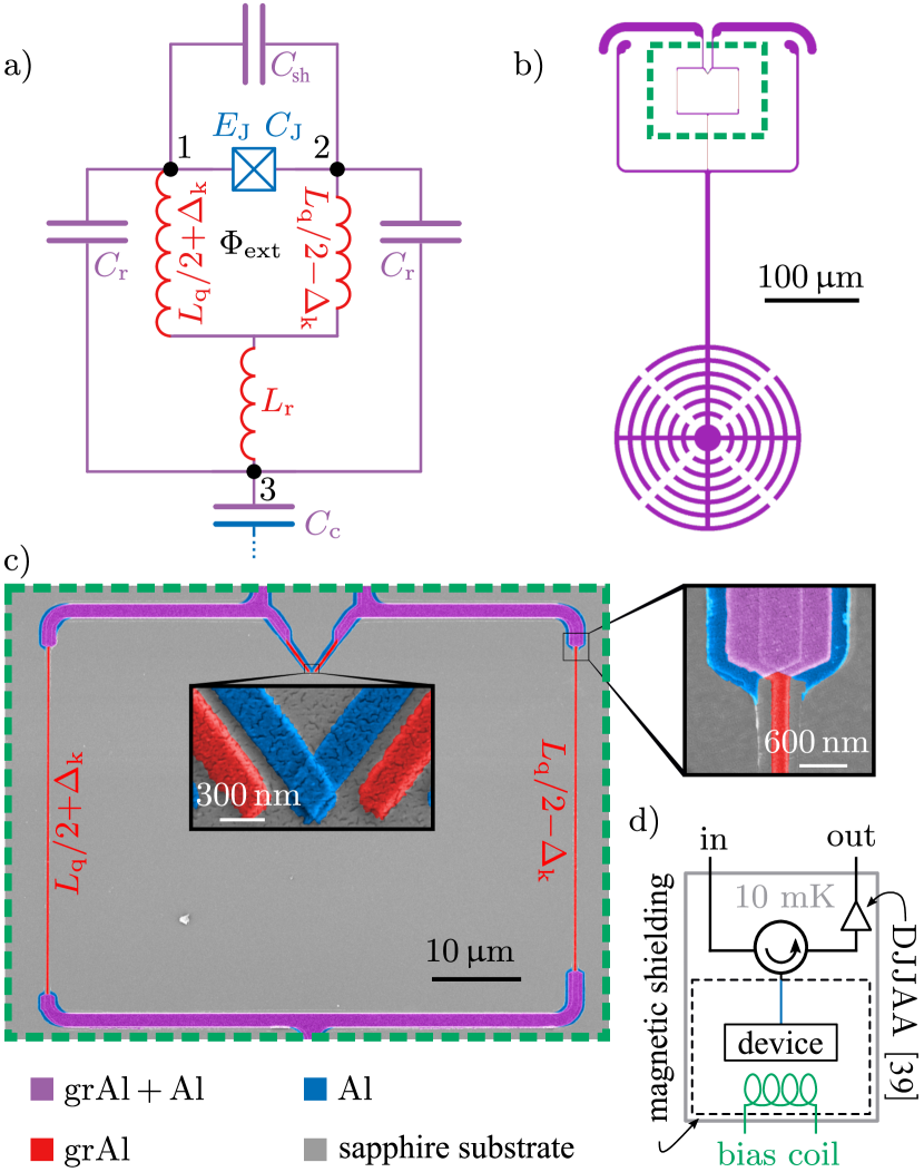
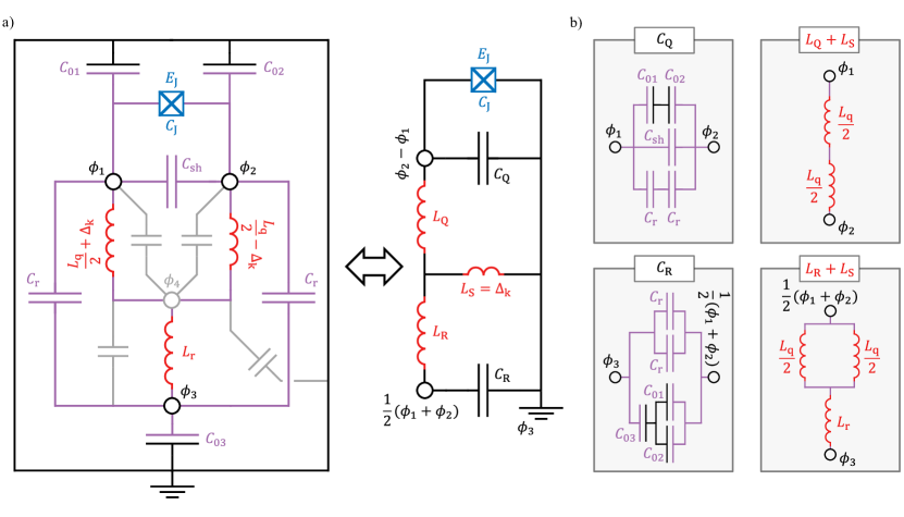
In Fig. 1a we present our lumped-element circuit design which consists of three superconducting islands, i.e. circuit nodes 1, 2 and 3, connected via kinetic inductors made of grAl. The resulting superconducting loop, interrupted by the JJ and threaded by external flux , implements a generalized flux qubit (GFQ) [33]. The loop inductance defines the inductive energy of the qubit, where is the magnetic flux quantum.
If the circuit is symmetric with respect to the vertical symmetry line through node 3, which means that nodes 1 and 2 have equal capacitances as well as equal inductances , the qubit and resonator modes are electromagnetically uncoupled. The main stray capacitances of the design are discussed in App. .1.
The current in the readout mode splits between the qubit loop branches and in case of perfect symmetry the net shared current with the qubit mode is zero. To engineer qubit-readout coupling we introduce the kinetic inductive asymmetry by designing different grAl inductor lengths for the two qubit inductors in the qubit loop with a total difference of squares of grAl wire with sheet inductance . In case of JJ arrays, this would translate into using different junction numbers or junction sizes for the two inductors. As a result, the readout mode current splits unevenly in the qubit loop and the circuit is equivalent to an inductively coupled qubit [34], where plays the role of the shared inductance.
In contrast to capacitive [35, 36] or conventional inductive [34, 31] coupling of flux qubits, one circuit node is eliminated by collapsing the readout mode into the qubit loop. We would like to highlight several practical advantages of this coupling scheme. First, removing a circuit node pushes the parasitic modes to higher frequencies, improving the spectral purity of the device. Second, by coupling the resonator mode capacitively to a readout line using the capacitance at node 3, the direct coupling of the qubit mode remains minimal thanks to the axial symmetry. Third, the qubit-resonator coupling can be designed to be purely inductive, loosening constraints on capacitor design, and possibly facilitating innovative flux-pumping schemes [24].
We model the Fig. 1a circuit in the harmonic oscillator basis of the linearized circuit eigenmodes:
| (1) |
where is the Josephson energy, and and are the bosonic creation and annihilation operators for the readout and qubit modes with eigenfrequencies and , calculated without the Josephson inductance. The qubit and readout modes are linear combinations of the common and differential modes, defined by the dimensionless coupling coefficients , derived in App. .1. If we neglect the nonlinearity of the granular aluminum wire, the JJ is the sole source of nonlinearity in the system, such that the intuitive picture of a nonlinear qubit and linear readout mode is justified for . Note that the coupling between readout and qubit vanishes for perfect symmetry, i.e. for .
In Fig. 1b we show the layout of the qubit-resonator design. A scanning electron micrograph of the qubit loop is shown in Fig. 1c. The qubit parameters can be tuned independently by adapting the length of the inductor , the junction area defining and , and the size of the shunt capacitor electrodes determining . This can be done entirely geometrically, without changing the circuit topology nor the oxidation parameters for the JJ or the grAl film. The lateral inset in Fig. 1c shows a section of the grAl wire. Thanks to the relatively large kinetic inductance offered by grAl [37, 38], it is sufficient to add a few squares of grAl film to one qubit branch to span the range from zero up to several nH of inductive asymmetry . Notably, this can be done with minimal disturbance to the geometric inductance and the capacitance matrix.
The central inset of Fig. 1c shows a scanning electron micrograph of the qubit Al/AlOx/Al junction. The entire device is fabricated on a c-plane sapphire substrate in a single lithographic step using a three-angle shadow evaporation technique, similar to Ref. [31]. The aluminum layers (20 nm and 30 nm) are shadow evaporated to define the junction, followed by a zero-angle deposition of a 70 nm layer of grAl with resistivities between 450 cm and 1000 cm depending on the device (cf. App. .2). The sample is mounted in a modular flip-chip architecture, anchored to the base plate of a dilution-cryostat at approx. 10 mK and it is measured in reflection, as shown in Fig. 1d. The output signal is amplified using a dimer Josephson junction array amplifier (DJJAA) [39] operating close to the quantum noise limit.
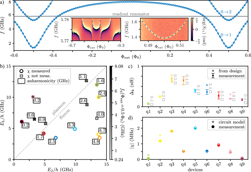
We measure the spectra of 14 different GFQs as a function of the external flux using two-tone spectroscopy. A typical spectrum is shown in Fig. 2a. Using the circuit Hamiltonian in Eq. 1 we fit the qubit and resonator spectra simultaneously to obtain the circuit parameters , , , and , while capacitors and are inferred from finite-element simulations (see App. .4). The coupling asymmetry is determined by the width of the avoided level crossing and , and are given by the measured qubit level structure.
The qubit spectra can be understood in terms of universal double-well physics [33], ranging from the fluxon-tunneling regime in which the barrier height exceeds the confining quadratic potential, to the single-well plasmon regime for . As summarized in Fig. 2b, the distribution of qubit frequencies and anharmonicities follow the underlying single and double-well physics: Towards the plasmon regime, the qubit frequencies increase whereas the anharmonicities decrease. Towards the fluxon regime, frequencies decrease while anharmonicities increase as expected from the exponential scaling of the qubit frequency with the barrier height [40]. At half-flux bias we measure coherence times in the range of 1 to 10 , likely limited by inductive losses in grAl as summarized in App. .5.
In Fig. 2c we compare the fitted and designed coupling asymmetry . The qubit-readout coupling is given by the sum of designed inductive coupling via and spurious capacitive asymmetries, which we parametrize as . These asymmetries can arise from asymmetric spurious capacitances of islands 1 and 2 to ground. From finite-element simulations we estimate a maximal value of due to a possible asymmetric displacement of the qubit chip with respect to ground. The corresponding uncertainties in the extraction of are given as errorbars in Fig. 2c.
The dispersive shift of the readout resonator is
where is the energy level sorted by the readout () and qubit () photon number. In Fig. 2d we compare the measured dispersive shifts to the expected model values using the extracted from spectroscopic measurements for nine qubits. The measured data is consistent with circuit model predictions for , validating the pure kinetic inductance coupling design.
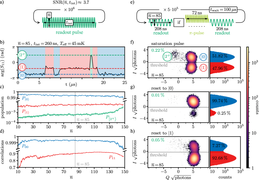
To quantify the readout performance of our device we have performed two sets of characterization: contiguous measurement correlations and active state reset, with pulse sequences detailed in Fig. 3a & e, respectively. We define the signal to noise ratio (SNR) in the - plane of the readout mode as the distance between pointer states corresponding to qubit in and , divided by the sum of their standard deviations. In all experiments we fix SNR , which is obtained by adjusting the integration times , ) ns depending on the different average photon numbers in the resonator.
In Fig. 3b we show an example section of a contiguously measured quantum jump trace for GFQ device q7. By applying a Gaussian mixture model to quantum jump traces with points for a given , we extract qubit populations in , and (see Fig. 3c) and correlations and for two successive measurements in the ground and excited state (see Fig. 3d), respectively. The correlations and serve as a measure of qubit readout fidelity, particularly useful to assess quantum demolition effects introduced by the readout drive. Similarly to Ref. [41], the resilience of the grAl GFQ to readout-induced leakage [42, 43, 44] is illustrated by the fact that up to , the qubit populations remain approximately constant, corresponding to an effective temperature of about 40 mK to 45 mK and residual excitations outside of the computational subspace remain below 0.1 %.
Within the qubit subspace, we observe a significant difference in the correlation of successive readout outcomes when the qubit is in the ground or excited state. Qubit measurements in the ground state are highly correlated, with for a broad range of readout powers. In contrast, we find that depends on the readout strength, with for . The difference between the measured and perfect correlation can be accounted for by summing three contributions: Energy decay during the measurement reduces by , which for can be as high as 6 % given the measured for device q7. Second, the qubit spectral shift and broadening induced by the readout tone will change the dissipative environment of the qubit [45] and might accelerate the relaxation from the excited to the ground state. The third contribution comes from demolishing effects activated when increasing [46], such as leakage outside of the qubit subspace [42]. The second and third contributions, which sum up to give at least of the infidelity, provide a measure for the performance of the qubit-readout coupling scheme and motivate future research efforts.
We implement active state preparation starting from the thermal state of the qubit by playing a conditional -pulse. The threshold to discriminate states and is determined by measuring the - plane distributions after a saturation pulse, as shown in Fig. 3f. Using , the fidelities to reset the qubit to its ground and excited state read and , respectively (cf. Fig. 3g & h). In the error budget for quantum state preparation, the fidelity of the -pulse of 99 % (cf. App. .6) is a negligible contribution compared to the decay during readout and quantum demolition effects. The measured performance for our GFQ devices are similar to results reported for fluxoniums and transmons [41, 47, 48] but below state-of-the-art fidelity reaching [49]. Currently, the main limitation for the readout performance is the energy relaxation time of the qubit, which can be significantly improved via material and design optimization [50].
We have demonstrated dispersive coupling between a harmonic mode and a generalized flux qubit consisting of a single junction shunted by a granular aluminum inductor. By embedding the harmonic readout mode into the high kinetic inductance loop of the flux qubit we implement a mechanism conceptually equivalent to inductive coupling, where the loop asymmetry is equivalent to the shared inductance. We validate the kinetic inductance coupling concept by comparing the spectra of 14 devices obtained via two-tone spectroscopy to a model including parasitic capacitances. We assess the suitability of the coupling mechanism for dispersive readout by performing quantum non-demolition readout with active state preparation fidelity and less than 0.1 % leakage outside the qubit computational space. Thanks to its ability to provide a local qubit-resonator interaction unaffected by on-chip capacitors, we believe that the minimalist qubit-resonator design presented here will provide an advantageous avenue for up-scaling superconducting quantum devices.
Acknowledgements
We are grateful to L. Radtke and S. Diewald for technical assistance. We acknowledge funding from the European Commission (FET-Open AVaQus GA 899561). Facilities use was supported by the KIT Nanostructure Service Laboratory. We acknowledge the measurement software framework qKit. The authors acknowledge support by the state of Baden-Württemberg through bwHPC. M.S., P.P, N.G. and T.R. acknowledge support from the German Ministry of Education and Research (BMBF) within the project GEQCOS (FKZ: 13N15683). D.B. and M.F. acknowledge funding from the German Federal Ministry of Education and Research (BMBF) within the project QSolid (FKZ: 13N16151). N.Z. acknowledges funding from the Deutsche Forschungsgemeinschaft (DFG – German Research Foundation) under project number 450396347 (GeHoldeQED). S.Gü., D.R. and W.W. acknowledge support from the Leibniz award WE 4458-5.
References
- Wallraff et al. [2004] A. Wallraff, D. I. Schuster, A. Blais, L. Frunzio, R.-S. Huang, J. Majer, S. Kumar, S. M. Girvin, and R. J. Schoelkopf, Strong coupling of a single photon to a superconducting qubit using circuit quantum electrodynamics, Nature 431, 162 (2004).
- Blais et al. [2021] A. Blais, A. L. Grimsmo, S. M. Girvin, and A. Wallraff, Circuit quantum electrodynamics, Rev. Mod. Phys. 93, 025005 (2021).
- Sung et al. [2021] Y. Sung, L. Ding, J. Braumüller, A. Vepsäläinen, B. Kannan, M. Kjaergaard, A. Greene, G. O. Samach, C. McNally, D. Kim, A. Melville, B. M. Niedzielski, M. E. Schwartz, J. L. Yoder, T. P. Orlando, S. Gustavsson, and W. D. Oliver, Realization of high-fidelity cz and -free iswap gates with a tunable coupler, Phys. Rev. X 11, 021058 (2021).
- Conner et al. [2021] C. R. Conner, A. Bienfait, H.-S. Chang, M.-H. Chou, É. Dumur, J. Grebel, G. A. Peairs, R. G. Povey, H. Yan, Y. P. Zhong, and A. N. Cleland, Superconducting qubits in a flip-chip architecture, Appl. Phys. Lett. 118, 10.1063/5.0050173 (2021).
- Kosen et al. [2022] S. Kosen, H.-X. Li, M. Rommel, D. Shiri, C. Warren, L. Grönberg, J. Salonen, T. Abad, J. Biznárová, M. Caputo, L. Chen, K. Grigoras, G. Johansson, A. F. Kockum, C. Križan, D. P. Lozano, G. J. Norris, A. Osman, J. Fernández-Pendás, A. Ronzani, A. F. Roudsari, S. Simbierowicz, G. Tancredi, A. Wallraff, C. Eichler, J. Govenius, and J. Bylander, Building blocks of a flip-chip integrated superconducting quantum processor, Quantum Science and Technology 7, 035018 (2022).
- Wu et al. [2021] Y. Wu, W.-S. Bao, S. Cao, F. Chen, M.-C. Chen, X. Chen, T.-H. Chung, H. Deng, Y. Du, D. Fan, M. Gong, C. Guo, C. Guo, S. Guo, L. Han, L. Hong, H.-L. Huang, Y.-H. Huo, L. Li, N. Li, S. Li, Y. Li, F. Liang, C. Lin, J. Lin, H. Qian, D. Qiao, H. Rong, H. Su, L. Sun, L. Wang, S. Wang, D. Wu, Y. Xu, K. Yan, W. Yang, Y. Yang, Y. Ye, J. Yin, C. Ying, J. Yu, C. Zha, C. Zhang, H. Zhang, K. Zhang, Y. Zhang, H. Zhao, Y. Zhao, L. Zhou, Q. Zhu, C.-Y. Lu, C.-Z. Peng, X. Zhu, and J.-W. Pan, Strong quantum computational advantage using a superconducting quantum processor, Phys. Rev. Lett. 127, 180501 (2021).
- Arute et al. [2019] F. Arute, K. Arya, R. Babbush, D. Bacon, J. C. Bardin, R. Barends, R. Biswas, S. Boixo, F. G. S. L. Brandao, D. A. Buell, B. Burkett, Y. Chen, Z. Chen, B. Chiaro, R. Collins, W. Courtney, A. Dunsworth, E. Farhi, B. Foxen, A. Fowler, C. Gidney, M. Giustina, R. Graff, K. Guerin, S. Habegger, M. P. Harrigan, M. J. Hartmann, A. Ho, M. Hoffmann, T. Huang, T. S. Humble, S. V. Isakov, E. Jeffrey, Z. Jiang, D. Kafri, K. Kechedzhi, J. Kelly, P. V. Klimov, S. Knysh, A. Korotkov, F. Kostritsa, D. Landhuis, M. Lindmark, E. Lucero, D. Lyakh, S. Mandrà, J. R. McClean, M. McEwen, A. Megrant, X. Mi, K. Michielsen, M. Mohseni, J. Mutus, O. Naaman, M. Neeley, C. Neill, M. Y. Niu, E. Ostby, A. Petukhov, J. C. Platt, C. Quintana, E. G. Rieffel, P. Roushan, N. C. Rubin, D. Sank, K. J. Satzinger, V. Smelyanskiy, K. J. Sung, M. D. Trevithick, A. Vainsencher, B. Villalonga, T. White, Z. J. Yao, P. Yeh, A. Zalcman, H. Neven, and J. M. Martinis, Quantum supremacy using a programmable superconducting processor, Nature 574, 505 (2019).
- Campagne-Ibarcq et al. [2016] P. Campagne-Ibarcq, P. Six, L. Bretheau, A. Sarlette, M. Mirrahimi, P. Rouchon, and B. Huard, Observing quantum state diffusion by heterodyne detection of fluorescence, Phys. Rev. X 6, 011002 (2016).
- Minev et al. [2019] Z. K. Minev, S. O. Mundhada, S. Shankar, P. Reinhold, R. Gutiérrez-Jáuregui, R. J. Schoelkopf, M. Mirrahimi, H. J. Carmichael, and M. H. Devoret, To catch and reverse a quantum jump mid-flight, Nature 570, 200 (2019).
- Léger et al. [2019] S. Léger, J. Puertas-Martínez, K. Bharadwaj, R. Dassonneville, J. Delaforce, F. Foroughi, V. Milchakov, L. Planat, O. Buisson, C. Naud, W. Hasch-Guichard, S. Florens, I. Snyman, and N. Roch, Observation of quantum many-body effects due to zero point fluctuations in superconducting circuits, Nature Communications 10, 10.1038/s41467-019-13199-x (2019).
- Stevens et al. [2022] J. Stevens, D. Szombati, M. Maffei, C. Elouard, R. Assouly, N. Cottet, R. Dassonneville, Q. Ficheux, S. Zeppetzauer, A. Bienfait, A. N. Jordan, A. Auffèves, and B. Huard, Energetics of a single qubit gate, Phys. Rev. Lett. 129, 110601 (2022).
- Chakram et al. [2022] S. Chakram, K. He, A. V. Dixit, A. E. Oriani, R. K. Naik, N. Leung, H. Kwon, W.-L. Ma, L. Jiang, and D. I. Schuster, Multimode photon blockade, Nature Physics 18, 879 (2022).
- Mehta et al. [2023] N. Mehta, R. Kuzmin, C. Ciuti, and V. E. Manucharyan, Down-conversion of a single photon as a probe of many-body localization, Nature 613, 650 (2023).
- Roch et al. [2014] N. Roch, M. E. Schwartz, F. Motzoi, C. Macklin, R. Vijay, A. W. Eddins, A. N. Korotkov, K. B. Whaley, M. Sarovar, and I. Siddiqi, Observation of measurement-induced entanglement and quantum trajectories of remote superconducting qubits, Phys. Rev. Lett. 112, 170501 (2014).
- Vijay et al. [2011] R. Vijay, D. H. Slichter, and I. Siddiqi, Observation of Quantum Jumps in a Superconducting Artificial Atom, Phys. Rev. Lett. 106, 110502 (2011).
- Heinsoo et al. [2018] J. Heinsoo, C. K. Andersen, A. Remm, S. Krinner, T. Walter, Y. Salathé, S. Gasparinetti, J.-C. Besse, A. Potočnik, A. Wallraff, and C. Eichler, Rapid High-fidelity Multiplexed Readout of Superconducting Qubits, Phys. Rev. Appl. 10, 034040 (2018).
- Swiadek et al. [2023] F. Swiadek, R. Shillito, P. Magnard, A. Remm, C. Hellings, N. Lacroix, Q. Ficheux, D. C. Zanuz, G. J. Norris, A. Blais, S. Krinner, and A. Wallraff, Enhancing Dispersive Readout of Superconducting Qubits Through Dynamic Control of the Dispersive Shift: Experiment and Theory, arXiv 10.48550/arXiv.2307.07765 (2023), 2307.07765 .
- Dumas et al. [2024a] M. F. Dumas, B. Groleau-Paré, A. McDonald, M. H. Muñoz-Arias, C. Lledó, B. D’Anjou, and A. Blais, Unified picture of measurement-induced ionization in the transmon, arXiv 10.48550/arXiv.2402.06615 (2024a), 2402.06615 .
- Hofheinz et al. [2009] M. Hofheinz, H. Wang, M. Ansmann, R. C. Bialczak, E. Lucero, M. Neeley, A. D. O’Connell, D. Sank, J. Wenner, J. M. Martinis, and A. N. Cleland, Synthesizing arbitrary quantum states in a superconducting resonator, Nature 459, 546 (2009).
- Kirchmair et al. [2013] G. Kirchmair, B. Vlastakis, Z. Leghtas, S. E. Nigg, H. Paik, E. Ginossar, M. Mirrahimi, L. Frunzio, S. M. Girvin, and R. J. Schoelkopf, Observation of quantum state collapse and revival due to the single-photon Kerr effect, Nature 495, 205 (2013).
- Geerlings et al. [2013] K. Geerlings, Z. Leghtas, I. M. Pop, S. Shankar, L. Frunzio, R. J. Schoelkopf, M. Mirrahimi, and M. H. Devoret, Demonstrating a Driven Reset Protocol for a Superconducting Qubit, Phys. Rev. Lett. 110, 120501 (2013).
- Murch et al. [2012] K. W. Murch, U. Vool, D. Zhou, S. J. Weber, S. M. Girvin, and I. Siddiqi, Cavity-Assisted Quantum Bath Engineering, Phys. Rev. Lett. 109, 183602 (2012).
- Shankar et al. [2013] S. Shankar, M. Hatridge, Z. Leghtas, K. M. Sliwa, A. Narla, U. Vool, S. M. Girvin, L. Frunzio, M. Mirrahimi, and M. H. Devoret, Autonomously stabilized entanglement between two superconducting quantum bits, Nature 504, 419 (2013).
- Lu et al. [2023] Y. Lu, A. Maiti, J. W. O. Garmon, S. Ganjam, Y. Zhang, J. Claes, L. Frunzio, S. M. Girvin, and R. J. Schoelkopf, High-fidelity parametric beamsplitting with a parity-protected converter, Nat. Commun. 14, 1 (2023).
- Gambino et al. [2015] J. P. Gambino, S. A. Adderly, and J. U. Knickerbocker, An overview of through-silicon-via technology and manufacturing challenges, Microelectronic Engineering 135, 73 (2015).
- Yost et al. [2020] D. R. W. Yost, M. E. Schwartz, J. Mallek, D. Rosenberg, C. Stull, J. L. Yoder, G. Calusine, M. Cook, R. Das, A. L. Day, E. B. Golden, D. K. Kim, A. Melville, B. M. Niedzielski, W. Woods, A. J. Kerman, and W. D. Oliver, Solid-state qubits integrated with superconducting through-silicon vias, npj Quantum Information 6, 10.1038/s41534-020-00289-8 (2020).
- Alfaro-Barrantes et al. [2021] J. A. Alfaro-Barrantes, M. Mastrangeli, D. J. Thoen, S. Visser, J. Bueno, J. J. A. Baselmans, and P. M. Sarro, Highly-conformal sputtered through-silicon vias with sharp superconducting transition, Journal of Microelectromechanical Systems 30, 253 (2021).
- Yu et al. [2022] J. Yu, Y. Zheng, S. Zhou, Q. Wang, S. Wu, H. Wu, T. Li, and J. Cai, Indium-based flip-chip interconnection for superconducting quantum computing application, in 2022 23rd International Conference on Electronic Packaging Technology (ICEPT) (2022) pp. 1–6.
- Smith et al. [2022] K. N. Smith, G. S. Ravi, J. M. Baker, and F. T. Chong, Scaling superconducting quantum computers with chiplet architectures, in 2022 55th IEEE/ACM International Symposium on Microarchitecture (MICRO) (2022) pp. 1092–1109.
- Field et al. [2024] M. Field, A. Q. Chen, B. Scharmann, E. A. Sete, F. Oruc, K. Vu, V. Kosenko, J. Y. Mutus, S. Poletto, and A. Bestwick, Modular superconducting-qubit architecture with a multichip tunable coupler, Phys. Rev. Appl. 21, 054063 (2024).
- Grünhaupt et al. [2019] L. Grünhaupt, M. Spiecker, D. Gusenkova, N. Maleeva, S. T. Skacel, I. Takmakov, F. Valenti, P. Winkel, H. Rotzinger, W. Wernsdorfer, A. V. Ustinov, and I. M. Pop, Granular aluminium as a superconducting material for high-impedance quantum circuits, Nature Materials 18, 816–819 (2019).
- Rieger et al. [2022] D. Rieger, S. Günzler, M. Spiecker, P. Paluch, P. Winkel, L. Hahn, J. K. Hohmann, A. Bacher, W. Wernsdorfer, and I. M. Pop, Granular aluminium nanojunction fluxonium qubit, Nature Materials 22, 194 (2022).
- Yan et al. [2020] F. Yan, Y. Sung, P. Krantz, A. Kamal, D. K. Kim, J. L. Yoder, T. P. Orlando, S. Gustavsson, and W. D. Oliver, Engineering Framework for Optimizing Superconducting Qubit Designs, arXiv 10.48550/arXiv.2006.04130 (2020), 2006.04130 .
- Smith et al. [2016] W. C. Smith, A. Kou, U. Vool, I. M. Pop, L. Frunzio, R. J. Schoelkopf, and M. H. Devoret, Quantization of inductively shunted superconducting circuits, Phys. Rev. B 94, 144507 (2016).
- Manucharyan et al. [2009] V. E. Manucharyan, J. Koch, L. I. Glazman, and M. H. Devoret, Fluxonium: Single Cooper-Pair Circuit Free of Charge Offsets, Science 326, 113 (2009).
- Bao et al. [2022] F. Bao, H. Deng, D. Ding, R. Gao, X. Gao, C. Huang, X. Jiang, H.-S. Ku, Z. Li, X. Ma, X. Ni, J. Qin, Z. Song, H. Sun, C. Tang, T. Wang, F. Wu, T. Xia, W. Yu, F. Zhang, G. Zhang, X. Zhang, J. Zhou, X. Zhu, Y. Shi, J. Chen, H.-H. Zhao, and C. Deng, Fluxonium: An alternative qubit platform for high-fidelity operations, Phys. Rev. Lett. 129, 010502 (2022).
- Rotzinger et al. [2016] H. Rotzinger, S. T. Skacel, M. Pfirrmann, J. N. Voss, J. Münzberg, S. Probst, P. Bushev, M. P. Weides, A. V. Ustinov, and J. E. Mooij, Aluminium-oxide wires for superconducting high kinetic inductance circuits, Supercond. Sci. Technol. 30, 025002 (2016).
- Grünhaupt et al. [2018] L. Grünhaupt, N. Maleeva, S. T. Skacel, M. Calvo, F. Levy-Bertrand, A. V. Ustinov, H. Rotzinger, A. Monfardini, G. Catelani, and I. M. Pop, Loss mechanisms and quasiparticle dynamics in superconducting microwave resonators made of thin-film granular aluminum, Phys. Rev. Lett. 121, 117001 (2018).
- Winkel et al. [2020] P. Winkel, I. Takmakov, D. Rieger, L. Planat, W. Hasch-Guichard, L. Grünhaupt, N. Maleeva, F. Foroughi, F. Henriques, K. Borisov, J. Ferrero, A. V. Ustinov, W. Wernsdorfer, N. Roch, and I. M. Pop, Nondegenerate parametric amplifiers based on dispersion-engineered josephson-junction arrays, Phys. Rev. Appl. 13, 024015 (2020).
- Rastelli et al. [2013] G. Rastelli, I. M. Pop, and F. W. J. Hekking, Quantum phase slips in josephson junction rings, Phys. Rev. B 87, 174513 (2013).
- Gusenkova et al. [2021] D. Gusenkova, M. Spiecker, R. Gebauer, M. Willsch, D. Willsch, F. Valenti, N. Karcher, L. Grünhaupt, I. Takmakov, P. Winkel, D. Rieger, A. V. Ustinov, N. Roch, W. Wernsdorfer, K. Michielsen, O. Sander, and I. M. Pop, Quantum nondemolition dispersive readout of a superconducting artificial atom using large photon numbers, Phys. Rev. Appl. 15, 064030 (2021).
- Dumas et al. [2024b] M. F. Dumas, B. Groleau-Paré, A. McDonald, M. H. Muñoz-Arias, C. Lledó, B. D’Anjou, and A. Blais, Unified picture of measurement-induced ionization in the transmon, arXiv 10.48550/arXiv.2402.06615 (2024b), 2402.06615 .
- Shillito et al. [2022] R. Shillito, A. Petrescu, J. Cohen, J. Beall, M. Hauru, M. Ganahl, A. G. Lewis, G. Vidal, and A. Blais, Dynamics of transmon ionization, Phys. Rev. Appl. 18, 034031 (2022).
- Cohen et al. [2023] J. Cohen, A. Petrescu, R. Shillito, and A. Blais, Reminiscence of classical chaos in driven transmons, PRX Quantum 4, 020312 (2023).
- Thorbeck et al. [2024] T. Thorbeck, Z. Xiao, A. Kamal, and L. C. G. Govia, Readout-induced suppression and enhancement of superconducting qubit lifetimes, Phys. Rev. Lett. 132, 090602 (2024).
- Walter et al. [2017] T. Walter, P. Kurpiers, S. Gasparinetti, P. Magnard, A. Potočnik, Y. Salathé, M. Pechal, M. Mondal, M. Oppliger, C. Eichler, and A. Wallraff, Rapid High-Fidelity Single-Shot Dispersive Readout of Superconducting Qubits, Phys. Rev. Appl. 7, 054020 (2017).
- Tholén et al. [2022] M. O. Tholén, R. Borgani, G. R. Di Carlo, A. Bengtsson, C. Križan, M. Kudra, G. Tancredi, J. Bylander, P. Delsing, S. Gasparinetti, and D. B. Haviland, Measurement and control of a superconducting quantum processor with a fully integrated radio-frequency system on a chip, Rev. Sci. Instrum. 93, 10.1063/5.0101398 (2022).
- Ristè et al. [2012] D. Ristè, C. C. Bultink, K. W. Lehnert, and L. DiCarlo, Feedback control of a solid-state qubit using high-fidelity projective measurement, Phys. Rev. Lett. 109, 240502 (2012).
- Sunada et al. [2022] Y. Sunada, S. Kono, J. Ilves, S. Tamate, T. Sugiyama, Y. Tabuchi, and Y. Nakamura, Fast readout and reset of a superconducting qubit coupled to a resonator with an intrinsic purcell filter, Phys. Rev. Appl. 17, 044016 (2022).
- Siddiqi [2021] I. Siddiqi, Engineering high-coherence superconducting qubits, Nat. Rev. Mater. 6, 875 (2021).
- Rymarz and DiVincenzo [2023] M. Rymarz and D. P. DiVincenzo, Consistent quantization of nearly singular superconducting circuits, Phys. Rev. X 13, 021017 (2023).
Appendix
.1 Circuit Models
The circuit is modeled in terms of the flux node variables and illustrated in Fig. S1. Following the canonical circuit quantization procedure, the Lagrangian reads
| (S1) |
where is the linearized circuit Lagrangian without the junction cosine potential, is the external flux through the qubit loop, is the capacitance matrix and the inverse inductance matrix, given by
and
The capacitances are obtained by finite-element simulations and include the capacitances between the islands on the chip and the sample holder (ground) . The junction parallel plate capacitance is excluded from the simulations and enters as an additional capacitance between nodes 1 and 2. A possible misalignment of the floating chip with respect to the symmetric sample holder environment gives the capacitive asymmetry
Extended circuit model
We start with a coordinate transformation from to , in which the linearized Lagrangian reads
The bare normal modes are then found by solving the eigenvalue problem
via the transformation matrix , such that the eigenbasis is written as . By introducing the conjugate momenta we obtain the diagonal linearized Hamiltonian
The eigenmodes are sorted with respect to their even and odd amplitudes across the junction, meaning that the qubit mode is defined as with and the readout mode as with . The back transformation from the harmonic oscillator (H.O) basis to the original flux node variables then reads
The common and differential modes can then be expressed in terms of qubit and readout modes as
| (S2) |
where we neglect the presence of the zero mode and the higher frequency mode associated with island 4. This simplification [51] is justified in our case because the mode associated with island 4, at , is sufficiently detuned from the spectrum of the device to give negligible corrections.
In the H.O. basis, coupling is solely mediated by the junction cosine term driven by the differential mode. To quantify it, we express the cosine argument in Eq. S1 via the above transformation and quantize the qubit-readout system and apply the canonical quantization procedure to the qubit and readout variables
Using this procedure we obtain the main text Hamiltonian
with
To obtain the qubit-resonator spectrum, we numerically diagonalize the Hamiltonian in the photon number basis using 15 and 30 basis states for the resonator and qubit, respectively.
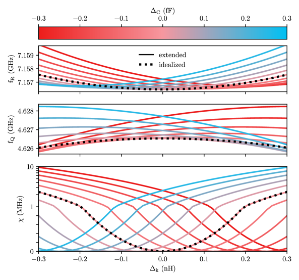
Idealized circuit model
While the procedure discussed in the previous section is sufficient to calculate the qubit-resonator spectrum, in order to gain intuition on the current and future designs, we find it instructive to also discuss the idealized model for a symmetric capacitive environment with . Below, we simplify the linearized extended circuit model in terms of the flux nodes , c.f. Eq. S2. Neglecting the capacitances to the center node 4, we can eliminate this inactive node via Kirchhoff’s rule of conserved currents
Further removing the zero mode with respect to the sample holder (ground), we can gauge as the new reference potential and write
| (S3) |
where we define
The inductive contribution to the Lagrangian is
Using Eq. S3,
which can be rewritten in matrix form as , with the inverse inductance matrix
To account for the contribution of the stray capacitances to ground, we treat the ground as a free node with conserved charge with respect to the floating islands and eliminate it from the Lagrangian by writing
where is the junction electrode capacitance to ground. The capacitive contribution to the Lagrangian then is
which can be rewritten in matrix form as , with the capacitance matrix
For , a transformation that diagonalizes both and simultaneously is
with the corresponding basis
Applying the above transformation for finite yields the matrices in the new basis
and
Finally, we define the qubit (Q) and readout (R) effective parameters, c.f Fig. S1b, as
such that the matrices can be rewritten as
and
as expected from the idealized inductively coupled circuit Fig. S1b which is similar to Ref. [41]. A numerical comparison between the idealized circuit and the extended circuit is shown in Fig. S2.
.2 Fabrication
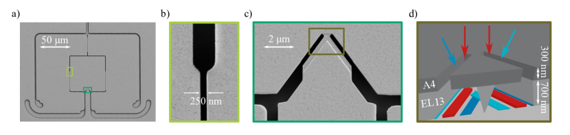
The devices are fabricated on a double-side polished c-plane 2 inch sapphire wafer with a thickness of 330 m. A two level resist stack MMA(8.5)MAA EL 13 (700 nm thick layer) / 950 PMMA A4 (300 nm thick layer) is spin-coated onto the wafer. An approx. thick gold layer is sputtered onto the wafer before e-beam writing. A 50 keV e-beam writer is used to pattern the mask. After e-beam exposure a 15 % Lugol solution is used to remove the gold. The resist stack is developed in an IPA/H20 3:1 solution at 6∘C for 90 s. Images of the resulting mask are shown in Fig. S3a to Fig. S3c. A Niemeyer-Dolan bridge shown in Fig. S3c & d is used to fabricate the Josephson junction. A commercial, controlled-angle e-beam evaporation machine (Plassys MEB 550S) is used to implement the three-angle evaporation process as shown in Fig. S3d. The evaporation steps are detailed in the paragraph below. For the mask liftoff, the wafer is immersed for two hours in a 60∘C Acetone bath, which is stirred for 2 minutes every 20 minutes.
Evaporation procedure
The evaporation machine has two chambers. The first chamber is used as loadlock and for oxidation, while the second UHV chamber is used for evaporation. In detail the following steps are used during evaporation:
-
•
Pump the loadlock for a minimum of 2 hours until the pressure is smaller than mbar.
-
•
Plasma cleaning process at 0∘ angle (Kaufman source parameters: 200 V beam voltage, 10 mA, 10 sccm O2, 5 sccm Ar)
-
•
Titanium evaporation with closed shutter (10 s with 0.2 nm/s)
-
•
Aluminium evaporation at - with open shutter (Al crucible 1, 20 nm with 1 nm/s)
-
•
Static oxidation (pure O2) of Josephson junction at 50 mbar for 4 min (+20 s to linearly increase the pressure to 50 mbar)
-
•
Aluminium evaporation at with open shutter (Al crucible 1, 30 nm with 1 nm/s)
-
•
Argon milling process at 0∘ angle (Kaufman source parameters: 400 V beam voltage, 15 mA, 0 sccm O2, 4 sccm Ar)
-
•
Regulate aluminium evaporation at 0∘ angle to 2 nm/s (Al crucible 2)
-
•
Regulate oxygen flow to 9.4 sccm and start planetary rotation with 5 rpm
-
•
Open shutter and evaporate for 35 s (corresponds to 70 nm of grAl)
-
•
Close shutter, terminate oxygen flow, stop planetary rotation, ramp down aluminium evaporation rate
Using the process described above grAl film resistivities at room temperature vary between 450 cm and 1000 cm as can be seen in Table S1.
| Date | [cm] |
|---|---|
| Sep 2022 | 620 |
| Sep 2022 | 660 |
| Nov 2022 | 840 |
| Nov 2022 | 940 |
| Nov 2022 | 640 |
| Dec 2022 | 880 |
| Dec 2022 | 1000 |
| Feb 2023 | 720 |
| Mar 2023 | 530 |
| Sep 2023 | 520 |
| Dec 2023 | 470 |
.3 Measured and fitted spectra
The circuit model described in App. .1 is fitted to the qubit spectra using a minimization method based on the python module scipy.minimize. In Fig. S4 the extracted data points are shown for each qubit. The resulting fit parameters , , , and are listed in Table S2 for each qubit. The measured dispersive shift is compared to its calculated value in the columns 7 and 8 of Table S2.
| device | [nH] | [nH] | [nH] | [GHz] | [fF] | [MHz] | [MHz] |
|---|---|---|---|---|---|---|---|
| q1 | |||||||
| q2 | |||||||
| q3 | |||||||
| q4 | |||||||
| q5 | |||||||
| q6 | |||||||
| q7 | |||||||
| q8 | |||||||
| q9 | |||||||
| q10 | - | - | |||||
| q11 | - | - | |||||
| q12 | - | - | |||||
| q13 | - | - | |||||
| q14 | - | - |
![[Uncaptioned image]](/html/2407.16342/assets/x7.png)
![[Uncaptioned image]](/html/2407.16342/assets/x8.png)
.4 Electrostatic finite-element simulations
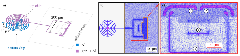
To obtain the capacitance matrix , electrostatic simulations are conducted, for which the electrostatic finite element solver Ansys Maxwell is used. The simulations are performed with a detailed 3D model of the copper sample box with refined mesh regions used for finer structures, as can be seen in Fig. S5. The mesh is automatically generated and therefore not perfectly symmetric with respect to the islands 1 and 2 (see Fig. S5.b) leading to convergence errors of 10 aF for the simulated capacitances, which are listed in Table S3 for all simulated devices.
| Qubit | [fF] | [fF] | [fF] | [fF] | [fF] | [fF] | [fF] | [fF] | [fF] | [fF] |
|---|---|---|---|---|---|---|---|---|---|---|
| q1 | ||||||||||
| q2 | ||||||||||
| q3 | ||||||||||
| q4 | ||||||||||
| q5 | ||||||||||
| q6 | ||||||||||
| q7 | ||||||||||
| q8 | ||||||||||
| q9 | ||||||||||
| q10 | ||||||||||
| q11 | ||||||||||
| q12 | ||||||||||
| q13 | ||||||||||
| q14 |
.5 Coherence times
A summary of the measured coherence times for 11 GFQ devices is shown in Table S4. We measure the free energy relaxation time , Ramsey decoherence time and echo decoherence time . Depending on the qubit, coherence times range from 1 - 10 and for each qubit we observe fluctuations in time on the order of microseconds.
The most dominant loss channel for the generalized flux qubits presented in this study is inductive loss, which can be estimated by evaluating Fermi’s Golden Rule via
| (S4) |
where is the inductive energy, the inductive quality factor, the flux operator in units of , and the qubit frequency. The measured energy relaxation times correspond to inductive quality factors of the order of to which is consistent with the expected inductive loss of granular aluminum [38]. The quality factors calculated from the measured energy relaxation times are tabulated in the fifth column in Table S4.
| device | T1 () | T () | T () | |
|---|---|---|---|---|
| q1 | / / / | / / | / / | 0.9 / 1.16 / 0.56 / 0.38 |
| q2 | 1.57 | |||
| q3 | 1.31 | |||
| q4 | 1.27 | |||
| q5 | 0.90 | |||
| q7 | 0.61 | |||
| q8 | 0.07 | |||
| q10 | 0.56 | |||
| q11 | / / / | / / | / / | 1.03 / 0.97 / 0.66 / 0.61 |
| q13 | 0.28 | |||
| q15 |
.6 Pulse calibration
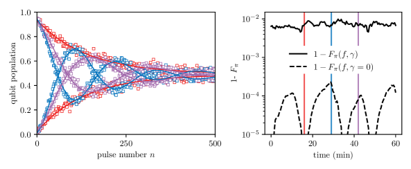
We fine-tune the -pulse amplitude by minimizing the beating pattern in the qubit population measured after a sequence of successive pulses. Three typical measurements are shown in Fig. S6a. The qubit population vs. pulse number is given by
| (S5) |
where is the frequency of the beating and accounts for energy decay. The amplitude and offset account for measurement errors. Using the parameters extracted from a fit of the data using Eq. S5, we define the - pulse fidelity as
In Fig. S6.b we plot and for repeated measurements over one hour. While the pulse calibration error drifts in time, the dominant error source is energy decay.
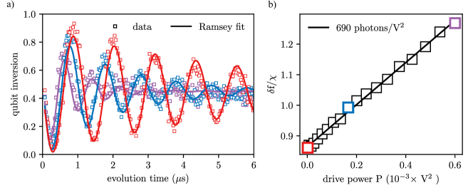
The photon number for the figures in the main text is calibrated using Ramsey interferometry while populating the readout resonator as depicted in Fig. S7.a. We use the linear AC-Stark shift in the dispersive regime
| (S6) |
where is the frequency shift of the qubit and is the dispersive shift of the resonator, to relate the circulating photon number to the power of the readout drive by fitting the Ramsey fringes for different . We apply a linear fit as it is depicted in Fig. S7.b.