long-short \setabbreviationstyle[acronym]long-short \NewEnvironeqn
| (1) |
A New Tightly-Coupled Dual-VIO for a Mobile Manipulator with Dynamic Locomotion
Abstract
This paper introduces a new dual monocular visual-inertial odometry (dual-VIO) strategy for a mobile manipulator operating under dynamic locomotion, i.e. coordinated movement involving both the base platform and the manipulator arm. Our approach has been motivated by challenges arising from inaccurate estimation due to coupled excitation when the mobile manipulator is engaged in dynamic locomotion in cluttered environments. The technique maintains two independent monocular VIO modules, with one at the mobile base and the other at the end-effector (EE), which are tightly coupled at the low level of the factor graph. The proposed method treats each monocular VIO with respect to each other as a positional anchor through arm-kinematics. These anchor points provide a soft geometric constraint during the VIO pose optimization. This allows us to stabilize both estimators in case of instability of one estimator in highly dynamic locomotions. The performance of our approach has been demonstrated through extensive experimental testing with a mobile manipulator tested in comparison to running dual VINS-Mono in parallel. We envision that our method can also provide a foundation towards active-SLAM (ASLAM) with a new perspective on multi-VIO fusion and system redundancy.
Index Terms:
mobile manipulator, visual-inertial odometry, dynamic locomotion, sensor fusionI Introduction
Mobile robots have been increasingly adopted in warehouses, while the manipulator arm has long operated in many manufacturing plants. A mobile manipulator, a combination of both, has become an attractive candidate for various tasks requiring dynamic movement and dexterous manipulation [puGeneralMobileManipulator2023a].
Historically, the mobile robot navigation problem comprises three sub-problems; mapping, localization, and motion planning [lluviaActiveMappingRobot2021a]. The first two problems are combined in the context of SLAM, proposed by Smith et al. in 1986 [chenOverviewMultiRobotCollaborative2023].
As the interest in this field grows, SLAM has progressed in various forms with different sensors (inertial measurement unit (IMU), light detection and ranging (LIDAR), time-of-flight (ToF), encoders and vision) with various fusion approaches (filtering or graph optimization) [servieresVisualVisualInertialSLAM2021]. In particular, visual-SLAM (VSLAM) has been popular in recent years due to its low cost and rich perception [chenOverviewVisualSLAM2022]. Often, VSLAM and visual odometry (VO) are used interchangeably in the literature with slightly different objectives; the former focuses on the global and consistent estimate of a device’s path, while the latter emphasizes the real-time pose estimations[servieresVisualVisualInertialSLAM2021]. One may regard the VO with loop-closure as a complete SLAM. To enhance the robustness and performance of SLAM, high rate IMU data have been incorporated to realize visual-inertial-SLAM (VISLAM) and visual inertial odometry (VIO), which was used for a tightly-coupled fusion with vision in multi-state constraint Kalman filter (MSCKF) [mourikisMultiStateConstraintKalman2007].
As the SLAM becomes more mature, a new frontier work in active-SLAM (ASLAM) has gained attention, aiming to unify all three sub-problems of navigration by bringing the task of actively planning robot locomotion to balance between exploitation (to decrease pose uncertainty) and exploration (to increase the map coverage) [ahmedActiveSLAMReview2023, lluviaActiveMappingRobot2021a].
A mobile manipulator can be a great platform to adopt ASLAM with additional sensor at the end-effector (EE) of the manipulator. However, many SLAM modules of mobile manipulators rely solely on the base platform aided by other costly sensors such as LIDAR [heOnTheGoRobottoHumanHandovers2022]. Some use EE localization with markers (e.g. ArUco Markers) [sandyConFusionSensorFusion2019, makinenRedundancyBasedVisualTool2020] which are often unusable in a rapidly changing unknown environment with dynamic locomotion [sandyConFusionSensorFusion2019, puGeneralMobileManipulator2023a]. Manipulator arms provide greater spatial flexibility and precise kinematic information through high-resolution encoders. However, due to transmission gaps and mechanical vibration, the EE may run into uncontrollable instability in global poses [ubezioKalmanFilterBased2019]. As a result, the manipulator can be in an uncertain state of kinematics and dynamics [luoEndEffectorPoseEstimation2021, makinenRedundancyBasedVisualTool2020], especially in the vicinity of singularity. Consequently, the nominal calibration of IMU noise is practically unsuitable for VIO systems when the EE is in dynamic motion.
Many mobile platforms use omnidirectional wheels to enable agile and holonomic movements. However, the performance of dead-reckoning estimates can be poor due to wheel slippage [aguilera-marinovicGeneralDynamicModel2017, puGeneralMobileManipulator2023a]. These wheels are not ideal for VIO, because excitations from uneven terrains can make the odometry diverge, especially when the field of view (FOV) is limited and features are poorly extracted with frequent occlusions [chaeRobustAutonomousStereo2020a]. Moreover, the initialization of VIO may become degenerative for some planar motions, resulting in inaccurate or unobservable spatiotemporal calibration [caoGVINSTightlyCoupled2022, yangOnlineSelfCalibrationVisualInertial2023]. In fact, for VINS-Mono [qinVINSMonoRobustVersatile2018], these motions can be problematic for its initial structure from motion (SfM), causing a delayed initialization.
Mobile manipulators are frequently equipped with an additional camera with IMU near the wrist or the EE (a.k.a. the eye-in-hand vision) for perception and manipulation. This makes two VIOs readily available from the system, one at the mobile base and the other near the EE. Combining these two sensory modules offers great flexibility when one sensor is unreliable or unavailable. However, the increased degree-of-freedom (DOF) comes at a price: increased system uncertainties due to coupled excitation when engaged in dynamic movement on different unknown terrains [puGeneralMobileManipulator2023a, vihonenLinearAccelerometersRate2016]. This results in highly non-uniform pose uncertainties for both VIO modules. Current SLAM systems often fail when the robot’s motion is too complex or the environment is too challenging, e.g. highly dynamic locomotion in cluttered environments [cadenaPresentFutureSimultaneous2016].
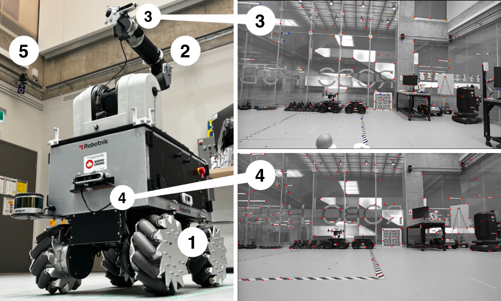
This motivates us to develop a more robust low-cost real-time dual-VIO system for a mobile manipulator with dynamic locomotion. In this paper, dynamic locomotion refers to coordinated movement involving both the base platform and the manipulator arm. Figure 1 depicts a basic setup for our study, which employs one set of a monocular camera with an IMU installed on the holonomic mobile base (3-DOF SUMMIT XL from Robotnik Inc.) and another set at the EE of the manipulator (7-DOF WAM Arm from Barrett Inc.).
To the authors’ best knowledge, this is the first paper introducing a tightly-coupled dynamic dual monocular VIOs on a mobile manipulator by combining proprioception (VIO) and kinesthesia (arm odometry) at the low level of the factor graph. Our key contributions are two-fold;
-
•
Construction of a new tightly coupled dual-VIO approach that balances robustness and computational complexity by incorporating the arm odometry factor.
-
•
Implementation of a modular distributed dual-VIO architecture that can be applied to general configurations of mobile manipulator platforms such as the one with multiple manipulators or a legged robot with a manipulator.
II Related Works
II-A Visual Inertial Odometry (VIO)
VIO is often divided into stereo-VIO and monocular VIO. We are interested in monocular VIO due to its simplicity and low cost without losing richness in information [chenOverviewVisualSLAM2022]. The stereo-VIO allows better 3D reconstruction but requires much higher data bandwidth. Since the monocular VIO relies on the triangulation between consecutive-frame features (as opposed to calibrated stereo triangulation), it is more prone to translational errors in the pose estimation [jeonRunYourVisualInertial2021].
Similar to most of SLAM algorithms, VIO consists of two main concurrent components:
II-A1 Front-end
The front-end module handles feature tracking and data extraction, which can be either sparse (feature) or dense (direct). The sparse methods have been predominant due to its robustness and efficiency. The performance of the front-end has a direct impact on the accuracy of the back-end [strasdatVisualSLAMWhy2012]. Hence, many works focused on improving the front-end with additional features (e.g. point and line features [hePLVIOTightlyCoupledMonocular2018], shape features[aslsabbaghianhokmabadiShapedbasedTightlyCoupled2023]), or image enhancements [songIRVIOIlluminationRobustVisualInertial2023].
II-A2 Back-end
The back-end module is often associated with sensor fusion. It may be categorized into either filter-based or graph-based. Filter-based methods rely on the principle of Bayes filters as their foundational form with certain relaxation [thrunProbabilisticRobotics2005], such as Gaussian approximation with EKF (e.g. MSCKF [mourikisMultiStateConstraintKalman2007]). Meanwhile, most graph-based methods (a.k.a. optimization-based) are derived from Bayesian inference and draw on recent advances in non-linear optimization solvers (e.g. Ceres [agarwalsameerandmierlekeirandtheceressolverteamCeresSolver2023] used in VINS-Mono [qinVINSMonoRobustVersatile2018]). When we assume simple linear Gaussian additive noise, maximum-a-posteriori (MAP) inference becomes equivalent to Kalman smoothing, and the tracking problem leads to the Kalman filter (KF) [dellaertFactorGraphsExploiting2021]. In practice, the filtering is preferred for high-rate and locally consistent data (IMU), while graph-based techniques are more efficient with low-rate, globally consistent, sparse features (images).
II-B VIO Fusion on Different Platforms
Modelling errors, sensor noise, feature mis-identification, and external disturbances are inevitable, hindering accurate estimation and introducing drifts [zhangRobustVisualOdometry2023]. To address these issues, VIO is frequently integrated with other sensors (e.g. global positioning system (GPS) or encoders) tailored towards a specific platform (e.g. aerial, legged, or mobile manipulator) for different environments (e.g. indoor or outdoor). For instance, unmanned aerial vehicles (UAVs) often require additional fixed positioning systems to provide low-rate correction. In outdoors, global navigation satellite system (GNSS) is commonly combined with VIO through optimization (e.g. [caoGVINSTightlyCoupled2022, zhangLightweightDriftFreeFusion2023]) or filtering (e.g. [xuHighAccuracyPositioningGNSSBlocked2023] based on MSCKF). Similarly, ultra wide-band (UWB) data can be fused with VIO (e.g. [caoVIRSLAMVisualInertial2021]) in indoors. However, fixed positioning systems are often unavailable in cluttered and unknown environments where mobile and legged robots operate. Instead, dead reckoning sensors are used with VIO. Vehicle encoders are commonly fused tightly into the VIO through the vehicle dynamics model (e.g. [liOnlineCalibrationSingleTrack2023]) or the kinematics model (e.g. [zhuVisualInertialRGBDSLAM2022]) to improve its robustness.
For legged robots, dynamic locomotion involves more sudden, jerky movements and impacts from ground touchdowns. These movements can significantly disrupt vision sensors, making it challenging for general VIO to estimate the robot’s state accurately [zhuEventCamerabasedVisual2023]. Hence, the additional joint encoders can be tightly coupled with VIO in the form of legged odometry factor in the factor graph to minimize the drift [wisthRobustLeggedRobot2019, kimSTEPStateEstimator2022, kangExternalForceEstimation2023].
In mobile manipulators, similar challenges arise not only from the ground impacts but also from the dynamic coupling between the base and the arm during the dynamic locomotion. As a result, the base disturbances (from wheel-ground interactions) propagate to the arm vibration, while the arm vibrations propagate back to the base body [aguilera-marinovicGeneralDynamicModel2017]. This oscillatory coupling amplifies the disturbance experienced at both the base and the EE VIO modules at certain modes, depending on the arm configuration. To address this challenge, [sandyConFusionSensorFusion2019] has tried to combine the VIO at the mobile base and that at the EE through moving horizon estimator (MHE) with the help of fiducial markers. The study suggests that the IMU is more effective in measuring the EE when compared to the base. The results also indicate that combining the base camera with the arm odometry helps to calibrate the cameras’ position with respect to the manipulator and the joint angle biases.
These findings motivated us to develop a dual-VIO system capable of localizing during dynamic locomotion in an unstructured, marker-free environment. This is achieved by simultaneously maintaining two factor-graph-based VIOs closely interacting with each other through arm kinematics.
II-C Multi-VIO Fusion
Depending on the degree or level with which multiple sensors are fused, one may classify a general multi-sensor fusion into two categories;
II-C1 Loosely-coupled
The core idea of loosely-coupled fusion is to blend poses from different estimators through a weighted combination. It is a simple and efficient way to unite various sensors and odometry algorithms through a filter-based method, and thus widely used in classical multi-modal fusion (e.g. [wuMultimodalInformationFusion2022]). [miillerRobustVisualInertialState2018] showed improved robustness in estimation and faster reconstruction of dense point cloud through a delayed fusion of multiple-VO integrating IMU into an error-state space KF. In fact, the multi-VIO can be considered as an example of mixture of experts (MoE) problem [morraMIXOMixtureExpertsBased2023]. However, failure of one sensor may cause deterioration or divergence of the whole estimation [wangHierarchicalDistributionbasedTightlyCoupled2023]. In practice, it is not easy to characterize different uncertainties and errors [morraMIXOMixtureExpertsBased2023].
II-C2 Tightly-coupled
Tightly-coupled methods prefer to fuse sensor data locally through a single optimization (e.g. non-overlapping multi-cameras [zhangVINSMKFTightlyCoupledMultiKeyframe2018, abateMultiCameraVisualInertialSimultaneous2023, zhangBalancingBudgetFeature2022]) and solve the pose and position jointly. Often, this approach relies on the flexibility and modularity of graph optimization. It may suffer from computational complexity due to scaling issues; the network keeps growing as more optimization states are introduced [morraMIXOMixtureExpertsBased2023].
In Multi-VIO Fusion, all methods above improved robustness with faster reconstruction, benefiting from the increased FOV and sensory redundancy. We propose a new technique involving a moderate tight-coupling111In some literature (e.g. [alkendiStateArtVisionBased2021]), the term ”semi-tight-coupling” has been used, but we adopt ”tight-coupling” as a more generally accepted term. to balance robustness and computational complexity while maintaining the independence of each VIO for system redundancy and failure recovery.
II-D Monocular-VIO and VINS-Mono
We are particularly interested in monocular-VIO due to its simplicity, as discussed in Section I. In particular, VINS-Mono has already demonstrated its robust performance with fewer resources [wisthRobustLeggedRobot2019],[jeonRunYourVisualInertial2021],[sharafutdinovComparisonModernOpensource2023] making it the baseline of many relevant works including ours. Readers interested in VINS-Fusion with a monocular setup may refer to the original works [qinVINSMonoRobustVersatile2018, lluviaActiveMappingRobot2021a] for in-depth fundamentals and architecture.
III Formulation of Proposed Dual VIOs
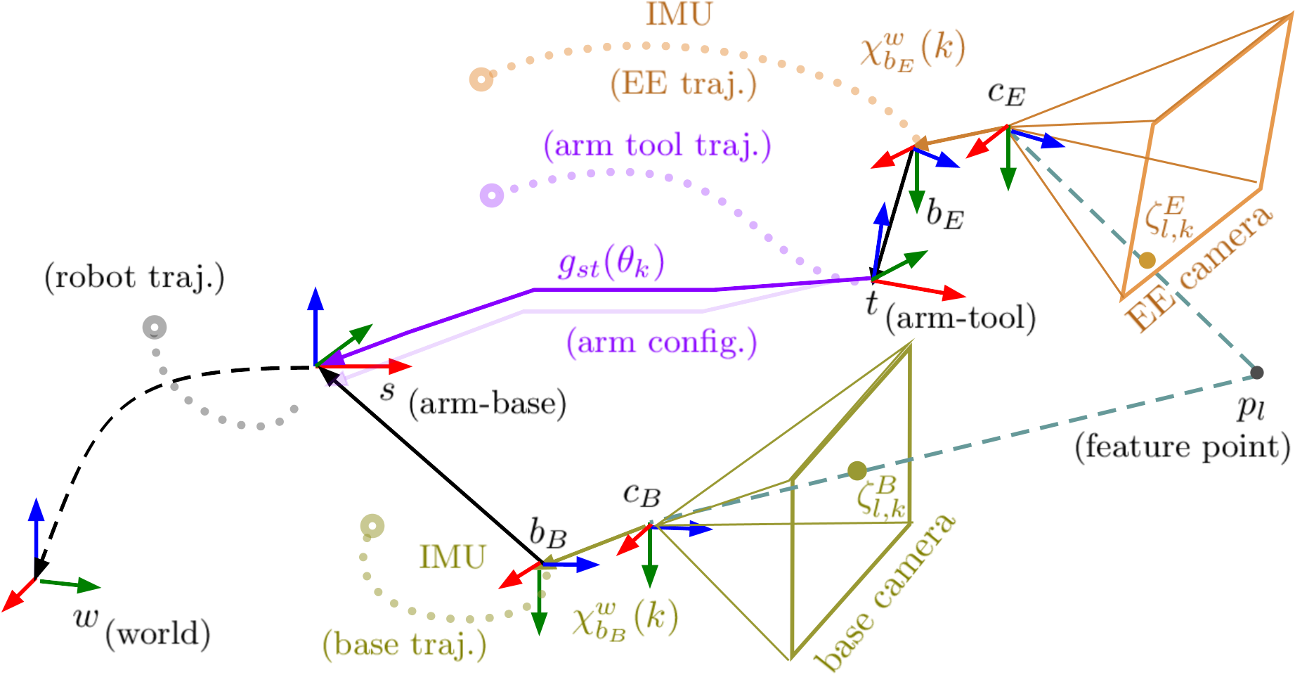
The objective of the dual-VIO is to estimate the poses () of the camera bodies with respect to their initial poses in the world frame () both at the mobile base () and the EE (), concurrently on the fly throughout locomotion. Figure 2 depicts configuration of coordinate frames used in this paper. For each motion variable (e.g. the ), the superscript denotes its frame of reference while the subscript denotes the frame whose motion is described by the variable. The pose estimate is directly obtained from the state at frame (denoted by ), which is to be estimated by the factor graph (See Eq. (III-A)).
III-A Formulation of Factor Graph
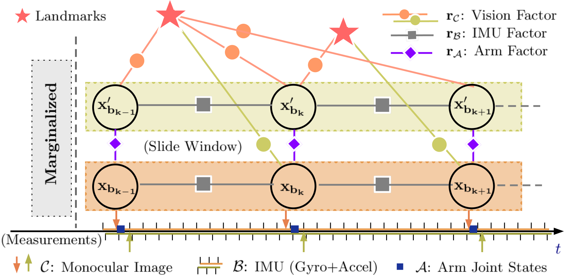
The proposed dual-VIO maintains two sets of factor graphs running concurrently in parallel to optimize two independent sets of states, one for the EE and the other for the base (i.e. and , respectively, in Fig. 2). This is distinct from fusing the optimized odometry in a later stage globally (i.e. loosely-coupled fusion) or jointly optimizing both states (i.e. tightly-coupled fusion). Instead, a moderate coupling is introduced through the arm odometry factor from the previously optimized states at the opposing VIO, propagated through the arm kinematics. This process is depicted in Fig. 3 in the form of primary and secondary VIO. Since either VIO is merely mirroring each other, we will denote as the primary VIO state and as the secondary one at the frame . For instance, from the EE’s standpoint, its primary VIO state (i.e. ) is , while its complementary one () is . This relative designation also applies to the geometric pose , i.e. the complementary VIO pose is if its primary VIO pose is .
Let us define as the set of integer indices for all the frames from to within the horizon. At each frame ( is also the discrete-time index for estimation within the horizon), the set of measurements from arm odometry is denoted by , and that for the IMU is denoted by between two consecutive frames . Similarly, denotes the set of all the image measurements associated with features that had occurred more than once until frame . We denote as an element of , i.e. (, ) to associate it explicitly with -th feature in -th camera frame that occurs more than once, starting from initial appearance.
Each VIO operates over the optimization variable for an independent receding horizon sliding window. Thus, contains all state vectors ’s () in the horizon. Besides, it also includes and which denote the relative position and the relative orientation, respectively, between the camera frame and the corresponding body frame. For computational efficiency, also contains inverse feature depth (denoted by , ) computed from all image measurements . Namely, the sliding window operates its optimization over {eqn} X = [x_b_0, …, x_b_n, p^b_c, q^b_c, λ_0, …, λ_m] In detail, the state at each frame is a vector {eqn} x_b_k = col(p_b_k^w, v_b_k^w, q_b_k^w, b_a, b_g), k ∈K where, denotes position, is velocity, is quaternion for orientation, and denote biases of accelerometer and gyroscope, respectively. Note that , and all convey pose information while taking different mathematical forms for different purposes.
The proposed factor graph can be solved by maximizing the posterior estimate of using optimization solvers (e.g. the Ceres solver [agarwalsameerandmierlekeirandtheceressolverteamCeresSolver2023]) with the objective function formulated based on bundle adjustment (BA) (similar to [kangExternalForceEstimation2023, qinVINSMonoRobustVersatile2018]) as {eqn} min_X &