Performance Analysis and Low-Complexity Beamforming Design for Near-Field Physical Layer Security
Abstract
Extremely large-scale arrays (XL-arrays) have emerged as a key enabler in achieving the unprecedented performance requirements of future wireless networks, leading to a significant increase in the range of the near-field region. This transition necessitates the spherical wavefront model for characterizing the wireless propagation rather than the far-field planar counterpart, thereby introducing extra degrees of freedom (DoFs) to wireless system design. In this paper, we explore the beam focusing-based physical layer security (PLS) in the near field, where multiple legitimate users and one eavesdropper are situated in the near-field region of the XL-array base station (BS). First, we consider a special case with one legitimate user and one eavesdropper to shed useful insights into near-field PLS. In particular, it is shown that 1) Artificial noise (AN) is crucial to near-field security provisioning, transforming an insecure system to a secure one; 2) AN can yield numerous security gains, which considerably enhances PLS in the near field as compared to the case without AN taken into account. Next, for the general case with multiple legitimate users, we propose an efficient low-complexity approach to design the beamforming with AN to guarantee near-field secure transmission. Specifically, the low-complexity approach is conceived starting by introducing the concept of interference domain to capture the inter-user interference level, followed by a three-step identification framework for designing the beamforming. Finally, numerical results reveal that 1) the PLS enhancement in the near field is pronounced thanks to the additional spatial DoFs; 2) the proposed approach can achieve close performance to that of the computationally-extensive conventional approach yet with a significantly lower computational complexity.
Index Terms:
Physical layer security (PLS), extremely large-scale array (XL-array), near-field communications.I Introduction
To fulfill the growing demands for applications like extended reality, metaverse, and holographic telepresence, the future sixth-generation (6G) wireless networks are anticipated to deliver significantly enhanced performance requirements than those of fifth-generation (5G) [1, 2]. Among others, by drastically boosting the number of antennas deployed at the base station (BS), the extremely large-scale array (XL-array) has been envisioned as a key enabler to significantly improve the spectral efficiency and spatial resolution of future wireless communication systems [3, 4, 5]. In particular, the huge aperture of XL-array introduces a fundamental change in the electromagnetic channel modeling, leading to a paradigm shift from traditional far-field communications towards new near-field communications [4]. More specifically, the electromagnetic waves in the near-field region should be precisely modeled by the spherical wavefront, which differs from the planar one typically assumed in the far-field counterpart.
This unique characteristic facilitates the beam energy to be focused at a specific location/region, termed beam focusing [6], bringing new design opportunities in various wireless systems [7, 8, 9, 10, 11, 12]. For example, for the typical multi-user communication systems, the authors of [7, 8] showed that using maximum ratio transmission (MRT)-based transmit beamforming can lead to near-optimal performance when the number of antennas is sufficiently large, thanks to the beam focusing gain. Later on, the beam focusing property was further investigated in near-field wideband multi-user communication systems for alleviating the spatial wideband effect [9]. In [10], a novel location division multiple access capitalizing on the beam focusing property was proposed to serve multiple near-field users simultaneously to enhance the spectrum efficiency. Meanwhile, the beam focusing characteristic stimulates plentiful novel applications, especially in the realm of sensing/localization-related scenarios. For instance, power in near-field simultaneous wireless information and power transfer (SWIPT) systems can be intentionally concentrated on the power-hungry receivers with very limited energy leakage rather than being dispersed along a specific direction as in the far-field SWIPT [11]. Furthermore, by properly exploiting the electromagnetic wavefront curvature, both angle and distance information can be inferred for near-field tracking using only a single XL-array, which is unachievable with its far-field counterpart [12]. Besides, the authors of [13] proposed a near-field integrated sensing and communications framework for multi-target detection. Despite the prominent merits of the beam focusing characteristic in various communication scenarios, security has been a long-standing concern in wireless communication systems, which deserves more in-depth research in the new near-field communications.
Physical layer security (PLS) is an effective complement to cryptography for safeguarding system security [14], making use of the physical attributes of wireless channels, such as interference, fading, noise, and disparity, while avoiding the complexity of generating and managing secret keys. There have been some initial attempts made to investigate PLS in the near-field communications [15, 16, 17, 18, 19, 20]. The work in [15] and [16] explored analog beam focusing for near-field PLS enhancement, considering the hardware costs associated with XL-arrays. Specifically, in [15], the PLS improvement in near-field wideband communications was investigated, wherein the interplay between near-field propagation and wideband beam split were addressed by utilizing the true-time delayer (TTD)-based analog beam focusing. The authors of [16] proposed an analog directional modulation precoding algorithm to offer secure transmissions at both angular and distance scales for a single-user multiple-input single-output (MISO) system. Further studies have shown various benefits of beam focusing in near-field secure transmission. In particular, it was shown in [17] that the beam focusing effect can be utilized to significantly improve the jamming rejection and the secrecy performance in near-field communications. The authors of [18] showed through numerical results that utilizing the new spatial DoF under spherical-wave propagation can enhance the secrecy rate and reduce the secure-blind areas. In [19], the authors studied PLS in the spherical-wave channel model, in which a secure transmission scheme was proposed to combat the cooperative eavesdropping for achieving the distance-domain security. Moreover, the authors of [20] introduced a near-field secure transmission framework using the classical hybrid beamforming architecture, revealing that the secrecy transmission of near-field communications is mainly determined by the relative distance of the eavesdropper with respect to the legitimate user.
However, most of the existing works either numerically demonstrated the performance improvement by exploiting the beam focusing effect or directly applied conventional far-field designs to near-field secure transmission. This thus fails to fully unveil the potential of near-field PLS, highlighting the need for more in-depth research on the sophisticated secure transmission design. For example, artificial noise (AN) has been extensively utilized in conventional far-field secure communications for PLS enhancement, which is designed deliberately to impair the channel of the eavesdropper while at the same time having a limited effect on the signal-to-interference-plus-noise ratio (SINR) at the legitimate users [21, 22]. However, it still remains unknown whether AN is advantageous to the near-field beam focusing-based PLS, and the analytical secrecy performance characterizations of near-field PLS remain lacking. More specifically, the following aspects are worthy of investigation: 1) whether the AN can utilize the beam focusing property embedded in near-field spherical wavefront; 2) under what conditions is AN most beneficial. Moreover, although the beam focusing function is appealing for its flexibility in controlling the beam energy distribution, its realization in practice is typically accompanied by prohibitively high computational complexity. For example, to fully exploit the potential of beam focusing, semidefinite programming is commonly adopted for designing the beamformer, whose computational complexity is on the order of [13] with denoting the number of antennas. This is far from practical, especially in the XL-array systems. Thus, it necessitates the computationally-efficient designs tailored for near-field PLS. To the best of the authors’ knowledge, the above two aspects have not yet been studied in the literature.
Motivated by the above, in this paper, we consider the security provisioning for a near-field communication system, where the BS equipped with an XL-array transmits confidential information to multiple near-field legitimate users in the presence of one near-field eavesdropper. Specifically, we delve into a challenging scenario in which the eavesdropper possesses the most favorable channel condition, under which joint beamforming with AN for achievable secrecy rate maximization is studied. The main contributions are summarized as follows.
-
•
First, we investigate secrecy provisioning in a near-field multi-user communication system using the beam focusing effect, where the achievable secrecy rate is maximized by jointly optimizing the transmit beamforming with AN subject to the transmit power constraint at the BS.
-
•
Second, to shed important insights into the new characteristics of near-field PLS, we consider a special case with one legitimate user and one eavesdropper involved. In particular, it is shown that incorporating AN into the beam focusing-based PLS can bring two prominent benefits. On the one hand, AN is essential to security provisioning, being capable of transforming an insecure system into a secure one. On the other hand, we reveal an interesting fact that allocating only a small proportion of power to AN can lead to significant security gain enhancement compared to the case without AN taken into account.
-
•
Third, for the general case with multiple legitimate users, we further propose an efficient yet low-complexity approach compared to the classical approach capitalizing on the semidefinite relaxation (SDR) and successive convex approximation (SCA). Specifically, the proposed approach starts with defining an interference domain to conceptualize the interference level among users, followed by a customized three-step identification framework for determining the beamforming optimization.
-
•
Finally, numerical results are provided to verify the performance gains attained by near-field secure transmission over the conventional far-field secure communication system, as well as the effectiveness of the proposed low-complexity approach. In particular, it is shown that 1) the AN can make good use of the beam focusing effect; 2) the extra spatial resources in the distance domain are highly beneficial to near-field PLS improvement; 3) the proposed low-complexity approach achieves very close secrecy performance to that of the conventional approach but with much lower computation cost.
Notations: We adopt the upper-case calligraphic letters, e.g., to denote discrete and finite sets. The superscript denote the conjugate transpose. represents the complex Gaussian distribution with mean and variance . Moreover, denotes the absolute value for a real number and the cardinality for a set. and denote the trace and rank of matrix ; indicates that is a positive semidefinite (PSD) matrix. stands for . denotes the standard big-O notation.
II System Model
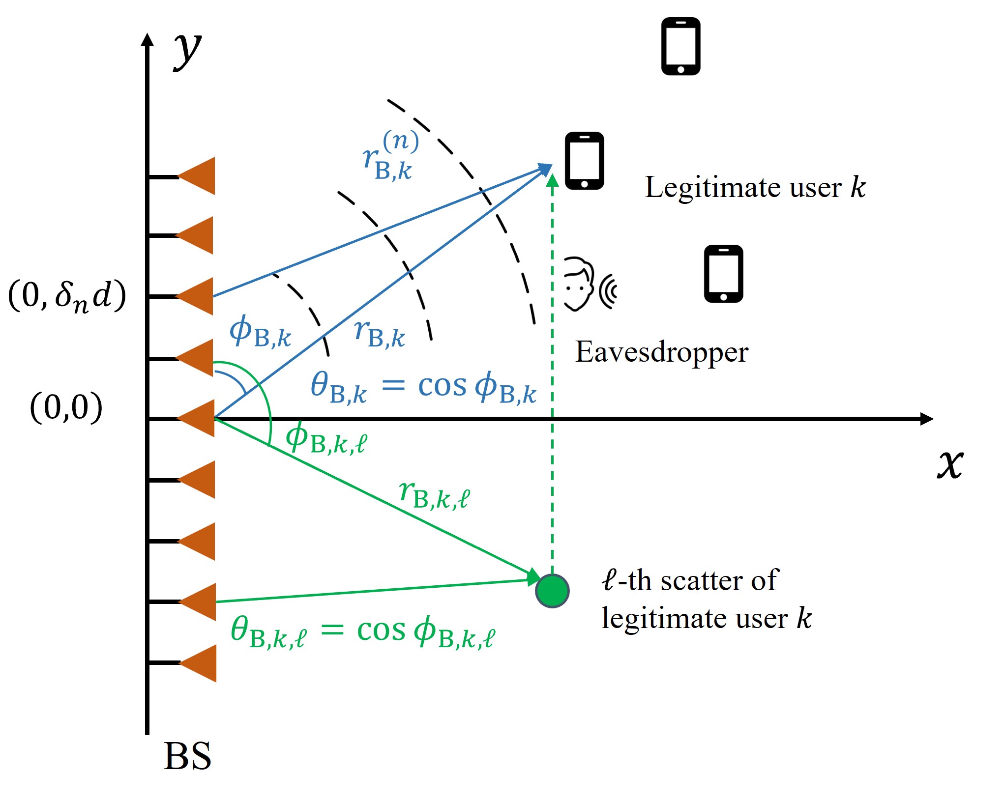
We consider a near-field multi-user downlink communication system as shown in Fig. 1, consisting of an XL-array BS, an eavesdropper, and multiple legitimate users, indexed by . The BS employs a uniform linear array (ULA) composed of antenna elements, while the legitimate users and the eavesdropper are single-antenna receivers. We assume that the legitimate users and eavesdropper are located in the near-field region, where the BS-user distances are greater than the Fresnel distance and smaller than the Rayleigh distance , with and denoting the antenna array aperture and carrier wavelength, respectively. Moreover, perfect channel state information (CSI) of the legitimate users and the eavesdropper is assumed to be available at the BS via effective near-field channel estimation and/or beam training methods, e.g., [23, 24, 25].
II-A Channel Model
For a typical near-field user, its channel should be modeled by the more accurate spherical wavefront, which is explained as follows. First, without loss of generality, we assume that the XL-array is placed along the -axis, centered at the origin of the coordinate system, i.e., . Accordingly, the coordinate of the -th antenna element, is given by , where and denotes the antenna spacing. As such, the distance between the -th antenna element of the XL-array and the legitimate user can be expressed as
| (1) |
where and denote the propagation distance and spatial angle from the origin to the legitimate user , respectively, with being the physical angle-of-departure (AoD). In this paper, we adopt the general near-field multipath channel model for each user, consisting of a line-of-sight (LoS) path and several non-line-of-sight (NLoS) paths induced by environment scatterers. Specifically, the LoS component of the near-field channel between the BS and the legitimate user can be modeled as
| (2) |
where denotes the complex-valued channel gain from the origin to the legitimate user ; is the channel steering vector, given by
| (3) |
Similarly, the NLoS channel components can be modeled as
| (4) |
where denotes the number of scatterers associated with the legitimate user . is the corresponding complex-valued channel gain of the -th NLoS path between the origin and the legitimate user . and denote the distance and spatial angle of the -scatterer with respect to the origin with being the physical AoD. Based on the above, the multipath near-field channel between the XL-array BS and the legitimate user is given by
| (5) |
The near-field channel between the XL-array BS and the eavesdropper can be characterized in a similar way, which is given by
| (6) |
where is the steering vector from the XL-array BS to the eavesdropper. and denote the corresponding complex-valued channel gains. In this paper, we consider the near-field PLS in high-frequency bands, e.g., millimeter-wave (mmWave) and terahertz (THz), for which the NLoS paths suffer from more severe path loss and thus have negligible power [26, 27]. Therefore, the channels between the XL-array BS and the legitimate user and the eavesdropper can be approximated as and , respectively.
II-B Signal Model
Let denote the signal vector emitted by the BS to the legitimate users, consisting of information-bearing signals and AN, given by
| (7) |
where and denote the beamforming vector and the information-bearing signal for -th legitimate user, respectively. In particular, to achieve secure communication, the AN vector is injected into the desired signal that is transmitted by the BS to impair the eavesdropper. As such, the received signals at the legitimate user and the eavesdropper are given by
| (8) | ||||
| (9) |
respectively, where and represent the additive white Gaussian noise (AWGN) at the legitimate user and eavesdropper, respectively. As such, the achievable rate of legitimate user is given by , where
| (10) |
In particular, to shed new insights into the PLS in near-field communications, we consider a challenging scenario, where the eavesdropper is closer to the BS than all the legitimate users. Furthermore, we assume that the eavesdropper is capable of canceling all multi-user interference before decoding the desired information [21, 22]. Accordingly, the channel capacity between the BS and the eavesdropper for wiretapping legitimate user is given by
| (11) |
The achievable secrecy rate of the legitimate user is given by . In this paper, we consider a general system sum secrecy rate maximization by optimizing the beamforming vectors and AN, i.e., and . The resulting optimization problem is formulated as
| (12a) | ||||
| s.t. | (12b) | |||
where (12b) denotes the transmit power constraint of the BS with being the maximum transmit power.
III Is AN Beneficial to PLS in Near-Field Communications?
To shed useful insights into the near-field secure transmission design, we consider in this section a special case with one legitimate user and one eavesdropper. Here, the index of legitimate user is dropped for notational convenience. In addition, for ease of implementation, we consider the MRT-based analog beamforming for both the legitimate user and the eavesdropper, i.e., and , to facilitate beam focusing, where and denote the power allocations to the legitimate user and eavesdropper, respectively. Accordingly, the achievable secrecy rate is given by
| (13) |
where holds by letting ;111To simplify the analysis, we assume that both the legitimate user and the eavesdropper have the same noise power. While for the case where the noise power differs, this equation still holds by performing the normalization of the noise power through the respective channel gains, i.e., and . and . To obtain a more tractable form of (III), we first make a key definition below.
Definition 1.
The correlation between any two near-field steering vectors is defined as
| (14) |
Remark 1.
In fact, the defined correlation can be viewed as two key factors affecting the system secrecy performance from different perspectives, as described below. First, from the perspective of security provisioning, the correlation measures the amount of information leakage from the legitimate user to the eavesdropper. On the other hand, from a communication perspective, the correlation reflects the interference intensity among legitimate users. Besides, it is worth noting that the correlation belongs to a fixed interval, that is, and has a symmetry property, i.e., . Accordingly, the secrecy rate in (III) can be reformulated as
| (15) |
where
| (16) |
III-A Near-field Secure Transmission without AN
First, we consider the case without AN and derive the secure condition directly.
Lemma 1.
The near-field secure transmission without AN is attainable only when the following condition holds
| (17) |
Proof: By removing the terms related to AN in (1), we have
| (18) |
The system is secure only when the condition holds, i.e., . This completes the proof.
Lemma 1 provides the secure condition for the case where AN is not adopted and reveals three key factors that affect the near-field secure transmission: the channel gains of the legitimate user and the eavesdropper, as well as the correlation between them. Notably, the secure condition is of the differential form and can, in fact, be considered as the effective quantity of information received by the legitimate user. Specifically, the first term indicates the quantity of transmitted information, whereas the second item signifies the information leaked to the eavesdropper. However, it is intractable to analyze the effects of these factors on the secure condition because the correlation generally decreases when the legitimate user is farther away from the eavesdropper, and vice versa. Furthermore, it can be observed that when the legitimate user and eavesdropper reside in the same spatial angle, the distance interval for satisfying the secure condition is very narrow. Outside of this interval, the near-field secure communication is not achievable. For example, when , GHz, , and m, the secure region for the legitimate user is approximately m, which is around portion of the near-field region. This leads to an intriguing question: Is AN advantageous to systems where the secure condition cannot be met? To answer this question, the next subsection will delve into the near-field secure transmission with AN taken into account.
III-B Near-field Secure Transmission with AN
We now consider the case where the AN is adopted for security provisioning. The resulting condition for guaranteeing security is presented as follows.
Lemma 2.
When the secure condition (17) does not hold, i.e., , the system becomes insecure. In such case, if
| (19) |
the system can regain security by allocating at least power to AN. In particular,
| (20) |
Proof: Please refer to Appendix A.
Remark 2 (How does AN make an impact?).
Regarding the derived condition in (19), we can draw several important insights: 1) The AN is crucial for near-field security provisioning, transforming insecure systems into secure ones. Moreover, it is observed from (20) that the power required for AN is irrespective of the total transmit power, but depends on the system setting, i.e., the location information of legitimate user and eavesdropper. 2) The condition for regaining security is jointly determined by the transmit power budget, channel gains of the legitimate user and eavesdropper, and the correlation factor. These factors are fixed, assuming the location information of the legitimate user and the eavesdropper (i.e., angle and distance) is known a priori. 3) It is worth noting that once the minimum power for secrecy provisioning is provided, the secure condition is independent of the power allocation design. This suggests that the secure condition serves as a boundary that is inherently embedded in the considered system. 4) From Lemma 2, we can conclude that there must exist the maximum secrecy rate of the considered system as long as the secure condition is satisfied properly. 5) The power allocated to AN for secure transmission can actually serve as an indicator of how secure a legitimate user is relative to the eavesdropper, hence acting as a crucial component of the proposed low-complexity approach in Section IV.
The secrecy rate in (1) is still in a complicated form, which, in general, is challenging to characterize its maximum value. To tackle this issue, we optimize the power allocation to achieve the maximum secrecy rate.
Lemma 3.
The optimal power allocation to achieve the maximum secrecy rate is given as follows.
-
•
If the following condition is satisfied
(21) the achievable secrecy rate first increases and then decreases, with the maximum attained with the following power allocation
(22) where
(23) -
•
Otherwise, the secrecy rate is monotonically decreasing with , and the maximum is achieved without allocating power to AN, i.e.,
(24)
Proof: Please refer to Appendix B.

Lemma 3 reveals an interesting result related to the effect of AN. Note that for the case without AN taken into account, it can be easily verified by Lemma 1 that when the secure condition is satisfied, the achievable secrecy rate increases monotonically with the power allocated to the legitimate user. However, for the case where AN is considered, the bound on which the secrecy rate changes from increasing first and then decreasing to monotonically decreasing is shown to be strictly greater than zero, i.e., . This suggests that even if the secure condition holds, i.e., , the secrecy rate will first increase and then decrease, indicating the ability of AN in enhancing the secrecy rate compared to the case without AN.
Example 1.
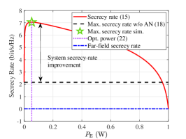
By means of Lemmas 2 and 3, we show the necessity of AN not only in the security provisioning but also in the secrecy rate enhancement. We in the following present a concrete example to show the effect of AN in detail. Specifically, we consider a near-field PLS system with , GHz, dBm, in which the legitimate user and eavesdropper are located in and represented by polar coordinates. We depict the achievable secrecy rate versus the power allocation to the eavesdropper in Fig. 2 to show the effect of AN on the achievable secrecy rate. Based on Lemmas 2 and 3, the effect of AN on the secrecy rate can be divided into three cases.
-
•
Case 1: When the system is insecure, i.e., , but the condition (19) is met, it is shown in Fig. 2(a) that the secrecy rate first increases and then decreases with , starting from the secrecy rate less than zero. Besides, it is observed that the insecure system regains its security using only a marginal amount of power, which is consistent with the required power derived in (20). Moreover, we observe that the maximum secrecy rate exists (marked by a pentagram), and the corresponding power allocation matches well with the derived optimal power allocation in (22).
-
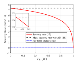
•
Case 2: For this case where the system is secure and the condition (21) holds, several important observations are made as follows. Interestingly, it is observed that the trend in the secrecy rate is similar to that in case 1, yet it is entirely distinct from the trend in the scenario without AN as described in Lemma 1. Besides, one can observe that even if the system is secure, allocating a moderate amount of power to the AN can significantly enhance the system secrecy rate. Additionally, it is worth noting that in most cases, the power allocation to AN is beneficial to the improvement of the secrecy rate. This is due to the fact that the AN can fully take advantage of the unique beam focusing characteristic, thereby significantly impairing the eavesdropper’s performance.
-
•
Case 3: For this case, the condition in (21) dose not hold, the secrecy rate monotonically decreases with the power allocated to the eavesdropper. In other words, the information leaked to the eavesdropper is very limited, and thus AN is no longer needed.
In what follows, we investigate the effects of angle and distance on the achievable secrecy rate. First, we present a useful lemma below.
Lemma 4.
The correlation of two near-field steering vectors can be approximated as
| (25) |
where and with and being the Fresnel integrals; and
| (26) |
Proof: The proof is similar to that in [Lemma 1,[28]] and hence is omitted for brevity.
Proposition 1.
The secrecy rate is monotonically decreasing with respect to the correlation between the legitimate user and eavesdropper. Moreover, combined with Lemma 4, we can draw the following insights:
-
•
The secrecy rate is symmetric in terms of the angle difference between the legitimate user and eavesdropper, i.e., . Besides, the secrecy rate reaches its minimum value when the angle difference is zero and, in general, decreases with the angle difference from both sides. This is because in (25) is symmetric regarding in (26), the maximum is obtained at .
-
•
The effect of distance on the secrecy rate is considerably complicated and thus difficult to analyze. Specifically, consider a typical case where . The envelope of is shown to decrease as in (26) increases [29] and thus decreases with the distance difference. However, the distance variation also affects the channel gains and the secrecy rate. The effect will be evaluated numerically later.
Proof: The proof is similar to that of Lemma 3, and thus is omitted here for brevity.
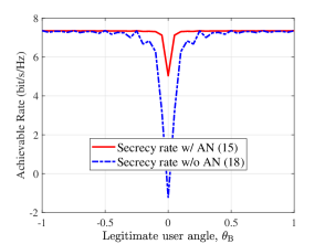
Example 2 (How do the angle and distance affect?).
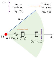
We provide a concrete example in Fig. 3 to demonstrate the effects of the spatial angle and distance of the legitimate user on the achievable secrecy rate. Specifically, the system setting is depicted in Fig. 3(a), and the secrecy rates versus the legitimate user angle and distance are plotted in Figs. 3(b) and 3(c), respectively, with the derived optimal power allocation in Lemma 3. First, it is observed from Fig. 3(b) that the secrecy rate is symmetric with respect to the angle difference. Specifically, the secrecy rate tends to degrade with the decrease of angle difference and reaches the minimum value when the angle difference is zero, which is in accordance with Proposition 1. An interesting observation is that the secrecy rate of the case aided by AN is smooth, while the secrecy rate of the case without AN appears to fluctuate. Moreover, as the angle difference increases, the fluctuations decrease. This is because the injection of AN can efficiently suppress the information leakage. In contrast, in the case without AN, the information is leaked to the eavesdropper to some extent due to the fluctuating correlation between them. Moreover, one can observe from Fig. 3(c) that AN is capable of guaranteeing the whole-distance secure transmission, while the scheme without AN fails to provide security gain. Additionally, it is observed that the secrecy rate first increases and then decreases with the legitimate user distance, rendering its non-linearity in the distance domain. This is consistent with the results in Proposition 1.
IV Low-Complexity Approach for Problem (P1)
The above analytical results are derived under the premise of analog beam focusing-based PLS with a single legitimate user. In the following, we investigate the more general case with multiple legitimate users. We shall first present the conventional approach and then propose a novel low-complexity approach for near-field secure transmission.
IV-A Conventional Approach
Problem (P1) is shown to be non-convex; thus it is hard to obtain the corresponding optimal solution. To this end, an efficient approach is proposed to obtain a high-quality solution, which is elaborated as follows. First, by defining , , , and , we can equivalently recast problem (P1) as follows
| (27a) | ||||
| s.t. | (27b) | |||
| (27c) | ||||
| (27d) | ||||
| (27e) | ||||
where
| (28) |
The main difficulties in solving the problem (P2) arise from the non-convex objective function (27a) and rank constraints (27d) and (27e), the solutions to which are described as follows. First, the rank-one constraints can be removed by invoking the SDR technique. While the non-convex objective function is replaced by the convex upper bound derived from the SCA method. More specifically, take as an example. Its global underestimators at any feasible point can be constructed by deriving the corresponding first-order Taylor approximation, given by
| (29) |
where the superscript denotes the iterative index of the associated optimization variable. As such, problem (P2) now becomes convex with respect to all optimization variables and thus can be efficiently solved by standard convex solvers, e.g., CVX. However, the conventional approach entails extremely high computational complexity, i.e., , especially in the considered XL-array systems, hence hindering its implementation in practice. To tackle the above issue, we propose a novel low-complexity approach in the next.
IV-B Low-Complexity Approach
Recall that the secrecy performance of the considered system is significantly affected by two aspects: information leakage and inter-user interference. These factors, however, are considered to be in conflict with each other due to the intrinsic trade-off between maximizing the sum-rate and minimizing the information leakage. In order to strike a good balance, the low-complexity approach should be properly designed to make the interference between legitimate users as small as possible, while at the same time reducing the information leakage as much as possible. To account for these effects, the proposed low-complexity approach is composed of three components: namely interference domain characterization, interference set construction, and beamformer determination, the detailed procedures of which are elucidated below.
IV-B1 Interference Domain Characterization
To characterize the interference domain, we first provide the following key propositions, namely beam width and beam depth.
Proposition 2 (-dB Beam width).
For a legitimate user , residing at , the -dB beam width characterizes the spatial angular width on the distance ring, i.e., [30], for which the normalized beam gain at an arbitrary observed angle-distance pair is above , i.e.,
| (30) |
where and .
Proof: The proof is similar to that of [31], and thus omitted for brevity.
Next, the -dB beam depth is characterized as follows.
Proposition 3 (-dB Beam depth).
For a legitimate user located at , the -dB beam depth characterizes the distance interval along the spatial angle , within which the normalized beam gain is larger than . Mathematically, is given by
| (31) |
where and denote the left and right boundaries of the beam-depth interval, respectively. and .
Proof: The proof is similar to that of [3], and thus omitted for brevity.
Remark 3 (What affects the beam depth?).
Proposition 3 indicates that the beam depth is considerably affected by the boundary , which is determined by the antenna size and the spatial angle. Note that is irrespective of the user distance, thus serving as a boundary when the spatial angle is fixed. Moreover, it can be verified that the beam depth is monotonically increasing as the user distance approaches the boundary, i.e., .
The -dB beam width and beam depth in Propositions 2 and 3 jointly characterize the surrounding area of a typical user within which the beam gain of this user is less than a predefined -dB threshold. However, in other words, if a beam steered towards another user falls into that user’s surrounding area, it will cause no less than -dB interference to that user. Therefore, the surrounding area can be regarded as the interference domain of a typical user, which is mathematically characterized as follows.
Proposition 4 (-dB Interference domain).
For a legitimate user , its -dB interference domain, denoted as , is approximated as a rectangular region formed by the corresponding beam width and beam depth, i.e., and , given by
| (32) |
IV-B2 Interference Set Construction
Based on the characterized interference domain, we can construct the interference set for each user accordingly. Specifically, we first make the following key definition.
Definition 2 (Interference set).
For a legitimate user , its interference set, defined as , consists of the legitimate users that are located within its -dB interference domain.
In the following, we present two useful propositions for facilitating the interference set construction. The first one is conceived from Proposition 3, where we observe that the beam depth tends to be infinity when the distance exceeds the boundary . However, since we consider the near-field secure transmission, the beam-depth interval should also fall within the near-field region. To this end, we below establish a distance threshold, denoted by , whose right boundary of beam-depth interval exactly lies in the Rayleigh distance.
Proposition 5.
For a legitimate user , there exists a distance threshold in the distance domain, beyond which the right boundary of the beam-depth interval is greater than the Rayleigh distance, which is given by
| (33) |
Specifically, the distance threshold has a maximum value with respect to , which is attained when is equal to zero, given by
| (34) |
Proof: Please refer to Appendix C.
Next, we show another useful proposition below.
Proposition 6 (Interference reciprocity).
For any two legitimate users , if is in user ’s interference set, then user shall also be included in the interfering set of user , i.e.,
| (35) |
Proof: Please refer to Appendix D.
Remark 4 (How do Propositions 5 and 6 facilitate the interference set construction?).
Proposition 5 derives a distance threshold, beyond which the distinct beam-depth intervals tend to be overlapped heavily. Furthermore, by means of the results of Proposition 6, we can conclude that users whose distance is greater than the threshold will definitely interfere with each other, and therefore should be grouped into one interference set. The above conclusions have two benefits in promoting the interference set construction. First, the complexity of the interference set construction can be greatly reduced with a large portion of users being located beyond the distance threshold. While at the same time, the interference reciprocity makes it possible to find users contained in overlapping interference sets sequentially, thus avoiding repeated checks. More importantly, these two conclusions are naturally complementary, making the low-complexity approach concise and intuitive.
Subsequently, since the interference set construction is largely affected by the user distribution, for ease of exposition, we divide it into two cases, as described below.
Linear distribution: We commence with the challenging case, i.e., all users lie in the same spatial angle, to demonstrate the construction process of the interference set. Based on Proposition 5, taking as the boundary, the whole user set can be divided into two separate subsets, denoted as and , which are given by
| (36) |
Then, according to Remark 4, all users in are interfering with each other, thereby being grouped into one interference set, i.e.,
| (37) |
While for the remaining legitimate users whose distance is smaller than , say user , its interference set can be mathematically given as
| (38) |
Uniform distribution: While for the general scenario where users are uniformly distributed within the near-field region, the interference set construction follows a similar idea as that of the linear distribution. More specifically, for a legitimate user , an additional step is to first find out which users are in its beam width, followed by the distance-domain identification as in (37) and (38). It is important to highlight that the proposed beam determination is independent of the user distribution once the interference sets are constructed. Accordingly, to provide a clearer illustration of the beam determination procedures, we primarily focus on the case of linear distribution in the following. Notably, the beam determination procedures can be directly applied to the uniform distribution case.
IV-B3 Beamformer Determination
The two key factors that affect the system secrecy performance, namely inter-user interference and information leakage, can be measured by the cardinality of the interference sets and the minimum required power for security in Lemma 2, respectively. Ideally, for data transmission of a typical legitimate user, if the secure condition is met and its interference set is empty, it indicates that this user is secure and interference-limited. Under such circumstances, the MRT-based beamforming can be performed directly, i.e., making the beamformer aligned with its channel. Otherwise, the beamformer needs to be optimized using the conventional approach in Section IV-A. To this end, the procedures of the beamformer determination can be divided into the following three cases:
Case 1 (No overlapping): In this case, the interference sets of all legitimate users and are empty, indicating limited interference among users. As such, the beamformer determination of each legitimate user depends on the secure condition solely. In particular, the beamformers of legitimate users who require power (i.e., the corresponding ) for security provisioning need to be optimized, and those of the remaining users shall employ MRT-based analog beamforming.
Case 2 (Full overlapping): For this case, all legitimate users are contained in an interference set, resulting in strong inter-user interference. Accordingly, we select one legitimate user with the minimum required power for security provisioning to conduct beamformer optimization. The remaining users adopt MRT-based beamforming directly. Particularly, it is worth noting that in practice, cases 1 and 2 rarely occur, while the following case 3 is relatively common.
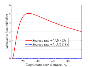
Case 3 (Partial overlapping): When there are multiple non-empty interference sets, the beamformer determination becomes much more involved. The key challenge in the case of partial overlapping is identifying where the overlapping is and how many users are included in the overlapping area. To conquer this issue, we propose a three-step identification framework for determining the beamformer optimization. Specifically, Fig. 4 shows an illustrative example of multiple non-empty interference sets, i.e., , , and , to demonstrate the detailed procedures.
-
1.
Identify the interference set of user : If it is empty, beamformer optimization is determined by the secure condition. Otherwise, identify the cardinality of the interference set of user and find the last user in the interference set , i.e., .
-
2.
Identify the interference set of user : Since the interference set of user is not empty, user ’s beamformer should be aligned. Meanwhile, user ’s beamformer optimization is determined by the secure condition.
-
3.
Identify the interference set of user : The interference set of user is also not empty. Thus, user ’s beamformer should be aligned with its channel. Last, identify the interference set of the last user in , i.e., , which is empty. Then, one legitimate user included in the interference set of , i.e., or , is selected according to the secure condition for beamformer optimization.
Remark 5 (How to design the beamformer of AN?).
In particular, it has been shown in Example 1 that by leveraging the beam focusing effect, AN can be deliberately adjusted to be focused on the eavesdropper to effectively suppress leaked signal power. At the same time, AN causes limited interference to legitimate users due to the worse channel conditions. Therefore, we can infer that for the design of near-field AN beamforming, the beamformer should be properly pointed towards the eavesdropper to achieve near-optimal secrecy performance. The corresponding performance will be evaluated by simulations in Section V.
IV-C Complexity Analysis
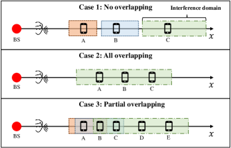
Next, we compare the computational complexity of the proposed low-complexity approach with that of the conventional approach in Section IV-A. To be more specific, consider the worst-case computational complexity of the low-complexity approach, assuming that the following extreme conditions are met. First, consider the scenario where users are located at the same spatial angle, and all users are distinguished by the defined boundary in Proposition 5, as shown in Fig. 5. Furthermore, it is assumed that users located on the left side of the boundary are sufficiently separable, i.e., no overlapping interference sets. Finally, we adopt the farthest boundary in (34) such that the separable region is large enough. In this way, the computational complexity is determined by the geometric distribution of legitimate users, which is derived as follows.
Proposition 7.
The distribution of the number of legitimate users that require beamformer optimization can be characterized as
| (39) | |||
Accordingly, the expectation of the number of legitimate users that the beamformer needs to be optimized is given by
| (40) |
where denotes the probability that the user is positioned in the separable region.
As such, the worst-case complexity of the proposed low-complexity approach can be characterized as [32]. While for the conventional approach, it entails a computational complexity of . For instance, when there are uniformly distributed legitimate users along one specific angle, the average number for beamforming optimization is . This indicates that the computational complexity of the proposed low-complexity approach is about at most of that of the conventional approach, rendering its great advantages in practical implementation.
V Simulation Results
In this section, we present numerical results to demonstrate the performance gains of the near-field PLS over its far-field counterpart, as well as the effectiveness of the proposed low-complexity beamforming scheme. The system parameters are set as follows. The BS equipped with antennas operates at a frequency of GHz to serve legitimate users. We consider the most representative and challenging scenario where the eavesdropper is positioned at , and three legitimate users are located at , , and , expressed in polar coordinates. Unless specified otherwise, the system parameters are described below. The reference path loss is dB, the maximum transmit power is dBm and the noise power is set as dBm, , and . Moreover, the number of NLoS paths from the BS to legitimate user/eavesdropper is set to and . The channel gains and are modeled as and , respectively, where , , and dB [9]. Specifically, we consider the following benchmark schemes for performance comparison.
-
•
Conventional scheme: This scheme performs the conventional approach to obtain the joint beamforming design with AN, thus serving as an upper bound for performance comparison.
-
•
Baseline scheme 1: The joint transmit beamforming with AN is configured to point towards their respective users, while only power allocations are optimized.
-
•
Baseline scheme 2: for which the transmit beamforming is optimized while the AN is directly aligned with the eavesdropper’s channel according to Remark 5.
-
•
Baseline scheme 3: for which the transmit beamforming of all legitimate users is aligned with the associated channel while optimizing the AN only.
V-A Effect of the Maximum Transmit Power
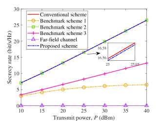
In Fig. 6, we study the effect of maximum transmit power on the achievable secrecy rate by different schemes. First, we observe that all involved schemes can guarantee secure transmission in the considered scenario, demonstrating the superiority of beam focusing in PLS improvement compared to the far-field counterpart. Besides, the secrecy rates by all schemes monotonically increase with the transmit power. Second, it is observed that baseline scheme 1 and the proposed scheme achieve a very close secrecy rate to that of the conventional scheme, which is consistent with Remark 5. It is worth noting that the conventional scheme is with prohibitively high computational complexity, whereas the proposed scheme achieves significantly lower computational complexity, rending its substantially higher efficiency. Next, the proposed scheme attains substantial performance gain over other benchmark schemes, e.g., around twice the secrecy rate by the baseline scheme 3. Last, it is observed that the secrecy rate of baseline scheme 3 tends to be saturated in the high transmit power regime. This is because the adopted MRT beamforming cannot exploit the spatial-domain DoFs, hence being unable to mitigate the multi-user interference effectively.
V-B Effect of the Number of Legitimate Users
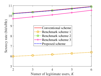
In Fig. 7, we evaluate the secrecy rate of the proposed scheme under various numbers of legitimate users. Specifically, legitimate users are sequentially selected from the distance interval in descending order, while all of them are positioned at the same angle . First, it is observed that the secrecy rates of all schemes increase with the number of legitimate users. This is because the newly added legitimate user with more favorable channel conditions is selected for data transmission, resulting in a higher secrecy rate. Second, we can observe that under different numbers of legitimate users, the proposed scheme is significantly superior to benchmark schemes 1 and 3, with a very marginal performance loss compared to the conventional scheme.
V-C Effect of the Spatial Angle
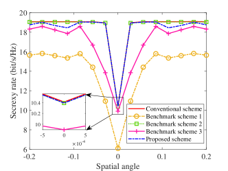
Next, we show the effect of the spatial angle on the secrecy rate by different schemes in Fig. 8. For clarity, we consider the scenario with one eavesdropper located at and two legitimate users. One of them is situated at , while the other one is placed at a distance of , with the spatial angle varying between . First, it is observed that the secrecy rates by all schemes experience severe performance degradation when the two legitimate users overlap with each other. This is because in this case, the inter-user interference is the most intense, and the information leakage is the strongest, thus resulting in the lowest secrecy rate. Moreover, an intriguing observation is that the secrecy performance of baseline schemes 1 and 3 experiences fluctuations across the entire spatial angle interval, In contrast, the proposed scheme only exhibits fluctuations within the large-angle regime, e.g., , but with a moderate amplitude. This is because baseline schemes 1 and 3 adopt the MRT-based analog beamforming without utilizing the abundant spatial DoFs, rendering them ineffective in mitigating the inter-user interference. While for the proposed scheme, the MRT beamforming is employed only when the angular separation between two legitimate users exceeds the beam width and the user with a changing angle is secure.
V-D Effect of the Distance
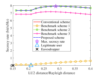
In Fig. 9, we illustrate the effect of legitimate user distance on the secrecy rate. Particularly, we consider a scenario consisting of one fixed eavesdropper (marked with a ), one fixed legitimate user, LU1 (marked with a triangle), and one position-changing legitimate user LU2. First, we can observe that the secrecy rates of all schemes remain unchanged when the LU2 distance is smaller than that of LU1, indicating that all power allocated to LU1. However, when the LU2 distance is greater than the LU1 distance, the secrecy rate of benchmark scheme 1 shows a monotonous increase. While the secrecy performance of other schemes tends to be increased first and then decreased, reaching a maximum marked with a purple pentagram. This is attributed to the non-linearity coupled effects of the channel gain and the correlation in terms of the LU2 distance, as stated in Proposition 1.
V-E Complexity Comparison
Last, we compare the runtime of the proposed scheme with that of the conventional scheme under different numbers of the legitimate users. Specifically, the simulation is conducted using Matlab on a computer equipped with Intel Core i- and GHz processor. It is clearly observed that the runtime of the proposed scheme is much shorter than the conventional scheme under different values of . Additionally, the runtime reduction achieved by the proposed scheme becomes more significant as increases. This is because the number of users requiring beamforming optimization tends to saturate in the large- regime, which aligns with the result in Section IV-C.
| Runtime (s) | |||
|---|---|---|---|
| Conventional scheme | |||
| Proposed scheme | |||
VI Conclusions
In this paper, we studied near-field secure communication in a multi-user MISO system, wherein multiple legitimate users and one eavesdropper are assumed to be located in the near-field region. To shed useful insights into the design of beam focusing-based near-field PLS, we first considered a special case with one legitimate user and one eavesdropper. In particular, it was unveiled that 1) AN is of great importance to the system security provisioning, making insecure systems secure again; 2) AN can bring pronounced performance gains using a moderate portion of power. Moreover, for the general case, we first introduced a suboptimal solution by invoking the SCA and SDR techniques. Subsequently, an implementation-friendly low-complexity approach tailored for beamforming design was proposed based on the introduced interference domain and the three-step identification framework. Numerical results are presented to illustrate the performance gains achieved by near-field PLS compared to the far-field counterpart, as well as the effectiveness of the proposed low-complexity approach. In the future, it is interesting to study more computationally-efficient near-field beamforming design to further improve the near-field PLS.
Appendix A Proof of Lemma 2
To verify Lemma 2, we first state a fact that all transmit power should be utilized for maximizing the secrecy rate [33]. Then, the secrecy rate in (1) can be expressed as
| (41) |
where
| (42) |
For ease of analysis, the secrecy rate in (41) can be further rewritten as the following form:
| (43) |
Next, we only need to find the condition, under which holds. Therefore, we define the following function
| (44) |
It is clearly observed that function in (A) is a quadratic function with respect to , whose discriminant can be expressed as
| (45) |
Due to the non-negativity of , that is, , the zeros of function always exist. Then, in order to obtain the zeros analytically, defined as and , the following two cases need to be considered:
-
1)
Same Zeros: In this case, by letting , we have
(46) Accordingly, function has two identical zeros, which are given by
(47) -
2)
Different Zeros: For this case, we have , then the two distinct zeros of function are given by
(48) Since is always smaller than , we only consider the case , i.e., . Notice that in this case, is either greater than zero or less than zero. Accordingly, when , we can obtain , hence indicating that the system security can be guaranteed at will. This fact is consistent with Proposition 1. Next, for the case , i.e., , we can infer that the value of is between zero and , thus unveiling the minimum power required to achieve system security.
Combining the above, we can derive the secure condition, i.e., , which thus completes the proof.
Appendix B Proof of Lemma 3
First, we rewrite the secrecy rate as , where . Then, obtaining the maximum secrecy rate is equivalent to finding the maximum value of function . To this end, we first obtain the first-order derivative of , which is given by . Notice that the monotonicity of the first derivative function above relies only on its numerator, so we study its numerator instead, which is given by,
| (49) |
First, it is shown that function is a quadratic function with respect to . Then, it can be easily verified that the correlation is smaller than one, i.e., , based on which we can easily obtain that and are always smaller than zero for various system settings, i.e. and . Accordingly, the property of function is determined by the sign of , where both the first and second terms appear to be positive under the settings considered. While for the last term, its sign can be divided into two cases. First, when , i.e., , then it is shown that the function is first greater than zero and then smaller than zero, thereby resulting in the secrecy rate first increasing and then decreasing. Therefore, the maximum secrecy rate does exist and is obtained at the zero of function , which is given by
| (50) |
However, on the other hand, when is satisfied, the function is always smaller than zero, resulting in a monotonically decreasing secrecy rate.
Appendix C Proof of Proposition 5
To prove Proposition 5, We only need to find the distance whose right boundary of the beam-depth interval is equal to the Rayleigh distance. As such, we have
| (51) |
Moreover, it can be easily verified that the maximum value is obtained at . Combining the above leads to the desired result.
Appendix D Proof of Prosition 6.
For ease of exposition, we assume , and then we prove Proposition 6 from both aspects of beam width and beam depth. First, from the beam-width perspective, if user is located within the beam width of user , user is definitely located within the beam width of user as well. This is because the beam width is monotonically increasing with the distance, thus resulting in . Next, from the beam-depth perspective, assume users and are located at the same angle, i.e., . In this case, if user locates within the beam depth of user , i.e., , we have
| (52) |
Notice that the right hand of (52) is exactly equal to . Therefore, user is located within the beam depth of user as well, thus completing the proof.
References
- [1] W. Saad, M. Bennis, and M. Chen, “A vision of 6G wireless systems: Applications, trends, technologies, and open research problems,” IEEE Network, vol. 34, no. 3, pp. 134–142, May 2020.
- [2] C. You, Y. Cai, Y. Liu, M. Di Renzo, T. M. Duman, A. Yener, and A. L. Swindlehurst, “Next generation advanced transceiver technologies for 6G,” arXiv preprint arXiv:2403.16458, 2024.
- [3] Y. Liu, Z. Wang, J. Xu, C. Ouyang, X. Mu, and R. Schober, “Near-field communications: A tutorial review,” IEEE Open J. Commun. Soc., vol. 4, pp. 1999–2049, Aug. 2023.
- [4] M. Cui, Z. Wu, Y. Lu, X. Wei, and L. Dai, “Near-field communications for 6G: Fundamentals, challenges, potentials, and future directions,” IEEE Commun. Mag., vol. 61, no. 1, pp. 40–46, Jan. 2023.
- [5] C. You, Y. Zhang, C. Wu, Y. Zeng, B. Zheng, L. Chen, L. Dai, and A. L. Swindlehurst, “Near-field beam management for extremely large-scale array communications,” arXiv preprint arXiv:2306.16206, 2023.
- [6] H. Zhang, N. Shlezinger, F. Guidi, D. Dardari, M. F. Imani, and Y. C. Eldar, “Beam focusing for near-field multiuser MIMO communications,” IEEE Trans. Wireless Commun., vol. 21, no. 9, pp. 7476–7490, Sep. 2022.
- [7] A. Kosasih and E. Björnson, “Finite beam depth analysis for large arrays,” IEEE Trans. Wireless Commun., early access, 2024.
- [8] H. Lu and Y. Zeng, “Communicating with extremely large-scale array/surface: Unified modeling and performance analysis,” IEEE Trans. Wireless Commun., vol. 21, no. 6, pp. 4039–4053, Jun. 2022.
- [9] Z. Wang, X. Mu, and Y. Liu, “Beamfocusing optimization for near-field wideband multi-user communications,” arXiv preprint arXiv:2306.16861, 2023.
- [10] Z. Wu and L. Dai, “Multiple access for near-field communications: SDMA or LDMA?” IEEE J. Sel. Areas Commun., vol. 41, no. 6, pp. 1918–1935, Jun. 2023.
- [11] Y. Zhang and C. You, “SWIPT in mixed near- and far-field channels: Joint beam scheduling and power allocation,” IEEE J. Sel. Areas Commun., vol. 42, no. 6, pp. 1583–1597, Jun. 2024.
- [12] A. Guerra, F. Guidi, D. Dardari, and P. M. Djurić, “Near-field tracking with large antenna arrays: Fundamental limits and practical algorithms,” IEEE Trans. Signal Process, vol. 69, pp. 5723–5738, 2021.
- [13] D. Galappaththige, S. Zargari, C. Tellambura, and G. Y. Li, “Near-field ISAC: Beamforming for multi-target detection,” IEEE Wireless Commun. Lett., early access, 2024.
- [14] Y.-S. Shiu, S. Y. Chang, H.-C. Wu, S. C.-H. Huang, and H.-H. Chen, “Physical layer security in wireless networks: A tutorial,” IEEE Wireless Commun., vol. 18, no. 2, pp. 66–74, Apr. 2011.
- [15] Y. Zhang, H. Zhang, S. Xiao, W. Tang, and Y. C. Eldar, “Near-field wideband secure communications: An analog beamfocusing approach,” IEEE Trans. Signal Process, vol. 72, pp. 2173–2187, 2024.
- [16] J. Chen, Y. Xiao, K. Liu, Y. Zhong, X. Lei, and M. Xiao, “Physical layer security for near-field communications via directional modulation,” IEEE Trans. Veh. Technol., early access, 2024.
- [17] J. Ferreira, J. Guerreiro, and R. Dinis, “Physical layer security with near-field beamforming,” IEEE Access, vol. 12, pp. 4801–4811, 2024.
- [18] G. J. Anaya-López, J. P. González-Coma, and F. J. López-Martínez, “Spatial degrees of freedom for physical layer security in XL-MIMO,” in Proc. IEEE 95th Veh. Technol. Conf. (VTC-Spring), Helsinki, Finland, Jun. 2022, pp. 1–5.
- [19] D. Yu, L. Yang, X. Gao, Y. Wu, and G. Yue, “Physical layer security in spherical-wave channel using massive MIMO,” in Proc. IEEE 31st Annu. Int. Symp. Pers., Indoor Mobile Radio Commun., Aug. 2022, pp. 1–6.
- [20] Z. Zhang, Y. Liu, Z. Wang, X. Mu, and J. Chen, “Physical layer security in near-field communications,” IEEE Trans. Veh. Technol., early access, 2024.
- [21] X. Yu, D. Xu, Y. Sun, D. W. K. Ng, and R. Schober, “Robust and secure wireless communications via intelligent reflecting surfaces,” IEEE J. Sel. Areas Commun., vol. 38, no. 11, pp. 2637–2652, Nov. 2020.
- [22] D. Xu, X. Yu, Y. Sun, D. W. K. Ng, and R. Schober, “Resource allocation for secure IRS-assisted multiuser MISO systems,” in Proc. IEEE Globecom Workshops (GC Wkshps), Waikoloa, HI, USA, Dec. 2019, pp. 1–6.
- [23] S. Liu, X. Yu, Z. Gao, J. Xu, D. W. K. Ng, and S. Cui, “Sensing-enhanced channel estimation for near-field XL-MIMO systems,” arXiv preprint arXiv:2403.11809, 2024.
- [24] Y. Zhang, X. Wu, and C. You, “Fast near-field beam training for extremely large-scale array,” IEEE Wireless Commun. Lett., vol. 11, no. 12, pp. 2625–2629, 2022.
- [25] C. Wu, C. You, Y. Liu, L. Chen, and S. Shi, “Two-stage hierarchical beam training for near-field communications,” IEEE Trans. Veh. Technol., Feb. 2024.
- [26] X. Wu, C. You, J. Li, and Y. Zhang, “Near-field beam training: Joint angle and range estimation with DFT codebook,” IEEE Trans. Wireless Commun., early access, 2024.
- [27] W. Liu, C. Pan, H. Ren, F. Shu, S. Jin, and J. Wang, “Low-overhead beam training scheme for extremely large-scale RIS in near field,” IEEE Trans. Commun., vol. 71, no. 8, pp. 4924–4940, Aug. 2023.
- [28] J. Chen, F. Gao, M. Jian, and W. Yuan, “Hierarchical codebook design for near-field mmwave MIMO communications systems,” IEEE Wireless Commun. Lett., vol. 12, no. 11, pp. 1926–1930, Nov. 2023.
- [29] Y. Zhang, C. You, L. Chen, and B. Zheng, “Mixed near- and far-field communications for extremely large-scale array: An interference perspective,” IEEE Commun. Lett., vol. 27, no. 9, pp. 2496–2500, Sep. 2023.
- [30] M. Cui and L. Dai, “Channel estimation for extremely large-scale MIMO: Far-field or near-field?” IEEE Trans. Commun., vol. 70, no. 4, pp. 2663–2677, Apr. 2022.
- [31] P. Ramezani, A. Kosasih, A. Irshad, and E. Björnson, “Exploiting the depth and angular domains for massive near-field spatial multiplexing,” IEEE BITS the Informa. Theory Mag., vol. 3, no. 1, pp. 14–26, Mar. 2023.
- [32] I. Pólik and T. Terlaky, “Interior point methods for nonlinear optimization,” Nonlinear Optimization, Springer, Berlin, Heidelberg, pp. 215–276, 2010.
- [33] X. Zhao, S. Lu, Q. Shi, and Z.-Q. Luo, “Rethinking WMMSE: Can its complexity scale linearly with the number of BS antennas?” IEEE Trans. Signal Process, vol. 71, pp. 433–446, Feb. 2023.