The Construction of a Soft Gripper
Based on Magnetorheological Elastomer with Permanent Magnet
Abstract
Recently, magnetorheological elastomers have become an interesting smart material with many new designs for robotics. A variety of applications have been built with magnetorheological elastomers, such as vibration absorbers, actuators, or grippers, showing that this material is promising for soft robotics. In this work, the novel concept of a gripper is proposed, exploring the features of a magnetorheological elastomer and permanent magnet. The gripper uses the energy of a permanent magnet to provide a self-closing gripping mechanism. The usage of flexible material enables one to hold delicate objects of various shapes. This paper presents the rolling effect of magnetorheological elastomer and permanent magnet, the design process, and the features of the soft gripper. The effectiveness of the soft gripper was validated in a series of experiments that involved lifting different objects.
Keywords magnetorheological elastomer gripper permanent magnet rolling effect
1 Introduction
In recent times, soft magnetic materials have become more important in robotics and control systems applications Rateni et al. (2015); Erb et al. (2016); Ren et al. (2019); Eshaghi et al. (2021). The classic usage of soft magnetic materials is mainly related to vibration control Li et al. (2014); Lin et al. (2023). Its flexibility and ability to change the mechanical properties under the control of a magnetic field allow the construction of vibration isolators and absorbers in commercial applications. However, recently, these materials became more interesting for robotic applications Erb et al. (2016); Bira et al. (2020); Böse et al. (2021), including the construction of haptic devices, soft grippers, and remote control of the robot by an external magnetic fieldMahoney and Abbott (2014); Popek et al. (2017); Culha et al. (2020).
In the literature, two kinds of magnetoactive material have been described. The first is a magnetorheological elastomer (MRE), an elastomer mixed with ferromagnetic particles. These materials’ preparation process and properties can be found in detail in the work Li et al. (2014); Bira et al. (2020); Böse et al. (2021); Bernat et al. (2022). The main properties of MRE are flexibility and reaction to the magnetic field due to a relative permeability of about 2-5. The cost of MRE material flexibility is lower permeability in comparison to rigid materials such as steel. The second magnetoactive material is an elastomer mixed with a hard magnetic material. It is also flexible, but it has a magnetic field. The fabrication process of this material can be seen in the work Erb et al. (2016). In this work, we focus on the first type of magnetorheological elastomer in robotics applications. The main problem with MRE material in robotic applications is its low permeability, which limits the design possibilities. As previous studies show, MRE requires strong magnetic fields Böse et al. (2021); Cramer et al. (2018) to be controlled or to produce large deformations. In the work Cramer et al. (2018) it is suggested that MRE requires further improvement of material parameters before being used in robotic applications. However, in our work, we show that MRE is already applicable to creating soft grippers.
In this work, we are particularly interested in the construction of the soft gripper, which in recent times has been strongly developed by researchers Rus and Tolley (2015); Rateni et al. (2015); Navas et al. (2021); Shintake et al. (2018); Pagoli et al. (2021). One of the applications in which soft grippers can be used in the food industry Pettersson et al. (2010); Dinakaran et al. (2023), because of the possibility to grasp and transport delicate products such as fruits or candies without damaging them. In general, soft grippers can be divided by the actuation principle. The most popular soft grippers are pneumatic and mechanical actuation. The primary role of soft pneumatic grippers represents PneuNet Mosadegh et al. (2014) or particle jamming Rus and Tolley (2015); Washio et al. (2022). They are controlled by variable pressure and therefore must be supplied with compressed air. On the other hand, the soft gripper’s fingers are moved by a cable-based mechanism Rateni et al. (2015), which represents a mechanical type. The soft gripper with pneumatic and mechanics actuation has good properties, however, they require a completed control system like an air compressor. Therefore, grippers based on actuation principles different from pneumatic or mechanical ones also play an important role. For example, in works Araromi et al. (2015); Shintake et al. (2015) the dielectric electroactive polymers are applied to build grippers.
An interesting alternative to building soft grippers is the application of magnetoactive materials with soft or hard magnetic particles. In the literature Zhang et al. (2021); Skfivan et al. (2019); Choi et al. (2020); Bernat et al. (2022); Guan et al. (2022), there exist some preliminary studies on how to build a gripper using MRE material (with soft magnetic particles). In the work Skfivan et al. (2019) the MRE fingers, which are based on a rigid skeleton, are controlled by varying magnetic fields. The gripper can hold varying objects and requires energy in the closed state. In work Zhang et al. (2021), the soft gripper is performed on an electromagnet and MRE membrane to create a suction cup. The studies Choi et al. (2020) show a mechanical gripper where the adaptive sking is built with MRE material. The gripper can adapt to different object shapes hence it can hold objects more delicate and precise. In the work Bernat et al. (2022); Guan et al. (2022) the initial concept of the MRE gripper with fingers was designed using a magnetorheological material controlled by an electromagnet. This gripper holds only lightweight objects and its gripping force is created only by stress caused by deformation from the held object. Finally, MRE can also be an auxiliary material for building a gripper like in works Choi et al. (2018, 2023), where the MRE creates a bladder for magnetorheological fluid. Another application of MRE to grippers as auxiliary material is its connection to shape memory alloy (SMA) presented in Yang et al. (2022). It is only responsible for improving the performance of SMA. As an alternative to MRE, the application of hard magnetic particles with flexible polymer is also used to build soft grippers, as shown in the work Ullrich et al. (2015); Pettersson et al. (2010); Ding et al. (2023); Gao et al. (2022). In this topic, the interesting review of magnetoactive materials with hard magnetic particles for the construction of microgrippers is presented in the work Eshaghi et al. (2021) where the most common configuration is to control the gripper by varying external fields. It is worth noticing that magnetoactive materials with hard magnetic particles are more difficult to fabricate than MRE.
The main goal of the presented work is to investigate a novel geometry concept for the MRE gripper. It is based on the interaction between the permanent magnet and the MRE stripe. We demonstrated that these elements can create a system like a mechanical rotational spring. Additionally, it is easy to control the gripper by pulling the electromagnet. Compared to the ideas presented in Zhang et al. (2021); Skfivan et al. (2019); Choi et al. (2020); Bernat et al. (2022); Guan et al. (2022); Böse et al. (2021); Cramer et al. (2018) a new effect of the rolling torque between the MRE and a permanent magnet is exploited to provide a self-closing state. To verify the proposed concept, the gripper prototype was built and tested in experiments.
2 The Gripper Concept
The gripper presented in this work is based on magnetorheological elastomer and the permanent magnet. The first is elastomer material with soft magnetic particles. Its main features are flexibility and reactive to the electromagnet field. The second is a permanent magnet that stores a lot of magnetic field energy. In our work, we used these elements to create a flexible magnetic spring.
2.1 The Magnetic Spring
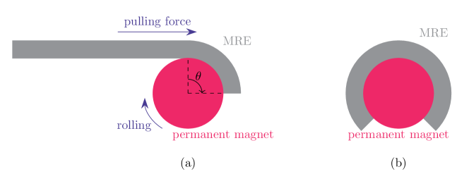
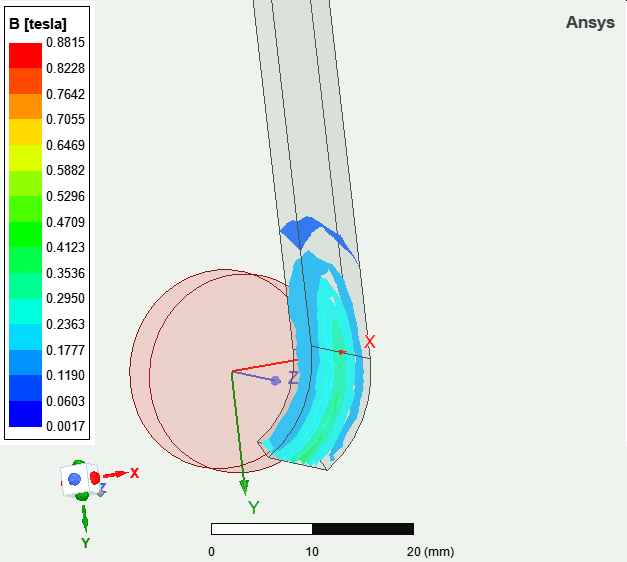
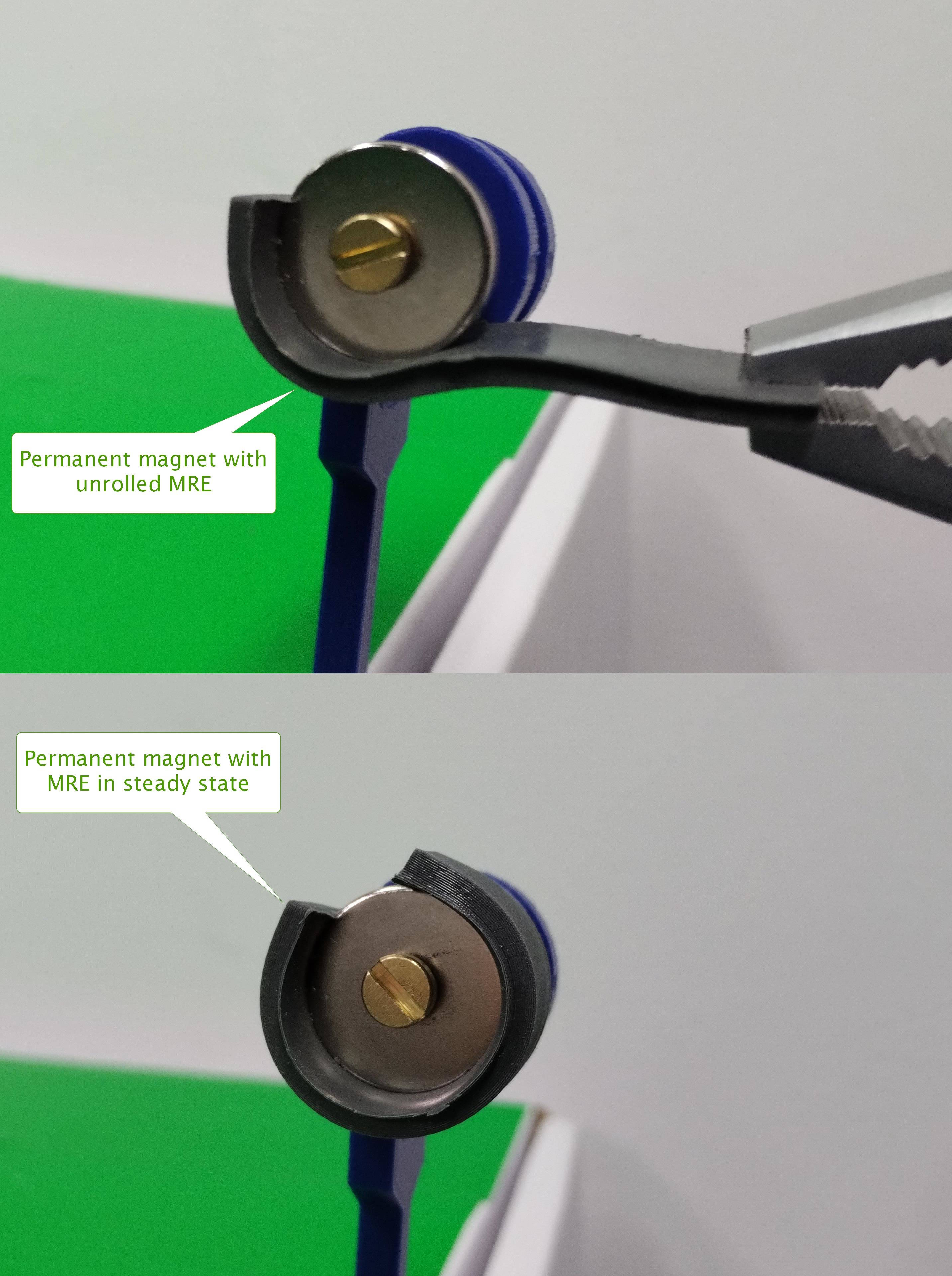
The main idea of the gripper is based on the magnetic spring created with a stripe built with MRE material and a cylindrical permanent magnet. Its behaviour can be illustrated in Fig. 1. The magnetic field of the permanent magnet causes MRE to be screwed onto the permanent magnet. To show that the connection of the MRE stripe with the permanent magnet produces the rolling torque, simulations were performed using ANSYS 2023 R1. The example of the field is shown in Fig. 2. It can be seen that the volume that contains the magnetic field is increasing with rolling MRE on the permanent magnet. Therefore, the torque is produced as long as MRE can be fully put on a permanent magnet.
The torque characteristic was calculated using the virtual work principle Ren and Razek (1992); Carpentier et al. (2014). The general expression for the coenergy is given as:
| (1) |
where describes the angle between MRE and permanent magnet (presented in Fig. 1), is the volume of the analyzed object, and , are the magnetizing field and magnetic field respectively found by solving Maxwell’s equation in the FEM software. The torque can be found by the derivative of the coenergy:
| (2) |
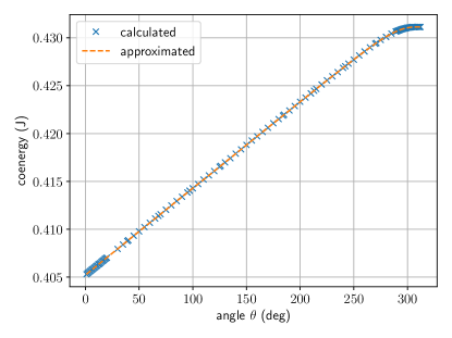
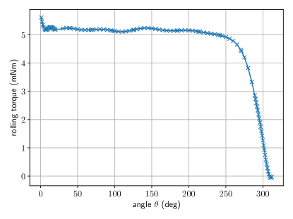
with respect to . In our work, in the first step, the coenergy of MRE stripe and the permanent magnet was found for a range of angle using ANSYS software. Then, to eliminate numerical errors in solving Maxwell’s equation, it was approximated by a spline function as shown in Fig. 3a. Finally, the torque was found by calculating the derivative. The results are visible in Fig. 3b. It is clear that the rolling torque for the angle between is almost constant. If the MRE stripe is almost all rolled on the permanent magnet, then the torque is going to . The behaviour can also be simply checked by experiment using the MRE stripe and a rolling permanent magnet, as shown in Fig. 4.
2.2 The Gripper Construction
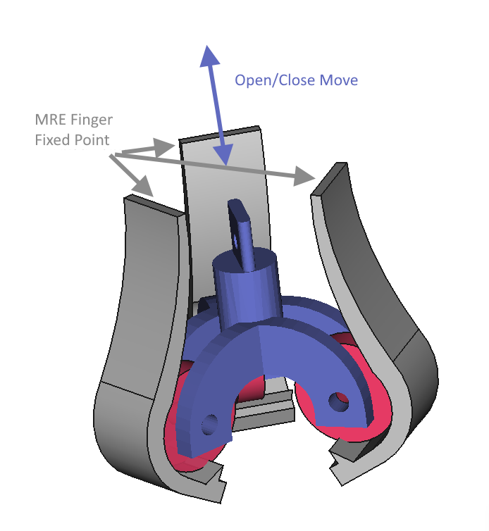
The gripper concept is to use three flexible springs as gripper fingers. The MRE stripes are fixed at the beginning and free to move on the permanent magnet. The field energy stored in a permanent magnet causes the MRE stripes to attempt to close. The MRE stripes have a small triangle near the handle object for a better grip. The concept is visualized in Fig. 5, where its open and closed states concept are presented. The beginning of the MRE stripes is fixed to some frame (not shown in the figure). In the open state, the extra force pulls the MRE stripes to make space for an object to be held. In the closed state, there is no extra force, and hence the permanent magnet and MRE elastomer (creating a flexible spring) are close to the element. The gripper shown in Fig. 5 works by moving the mounting frame with permanent magnets. The moving frame has been designed in such a way that there was free space for holding objects between permanent magnets. However, the force can also be attracted to the MRE stripe, and hence the permanent magnet mounting frame has a fixed position. The advantage of MRE is the possibility to easily mount MRE in the frame and it interacts with a permanent magnet, giving the self-closing state.
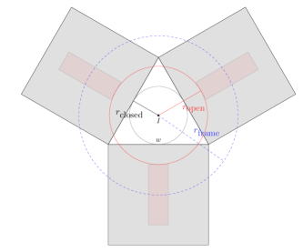
The size of the gripped objects depends on the position of permanent magnets and MRE fingers. In Fig. 6 two marked circles are showing the space for cylindrical objects in the open and closed state. In the open state, objects are bounded by permanent magnets, which are shown by a circle with radius . The following relationship describes the connections between radius in the open state, mounting frame radius (place for the center of permanent magnets) and permanent magnet diameter . In the closed state, objects are bounded by MRE fingers of minimal size given by a circle with radius . It is easy to calculate using equilateral triangle relationships that the width of the finger is related to the radius in the closed state as where is the width of the MRE finger.
2.3 Preparation of Magnetorheological Elastomers
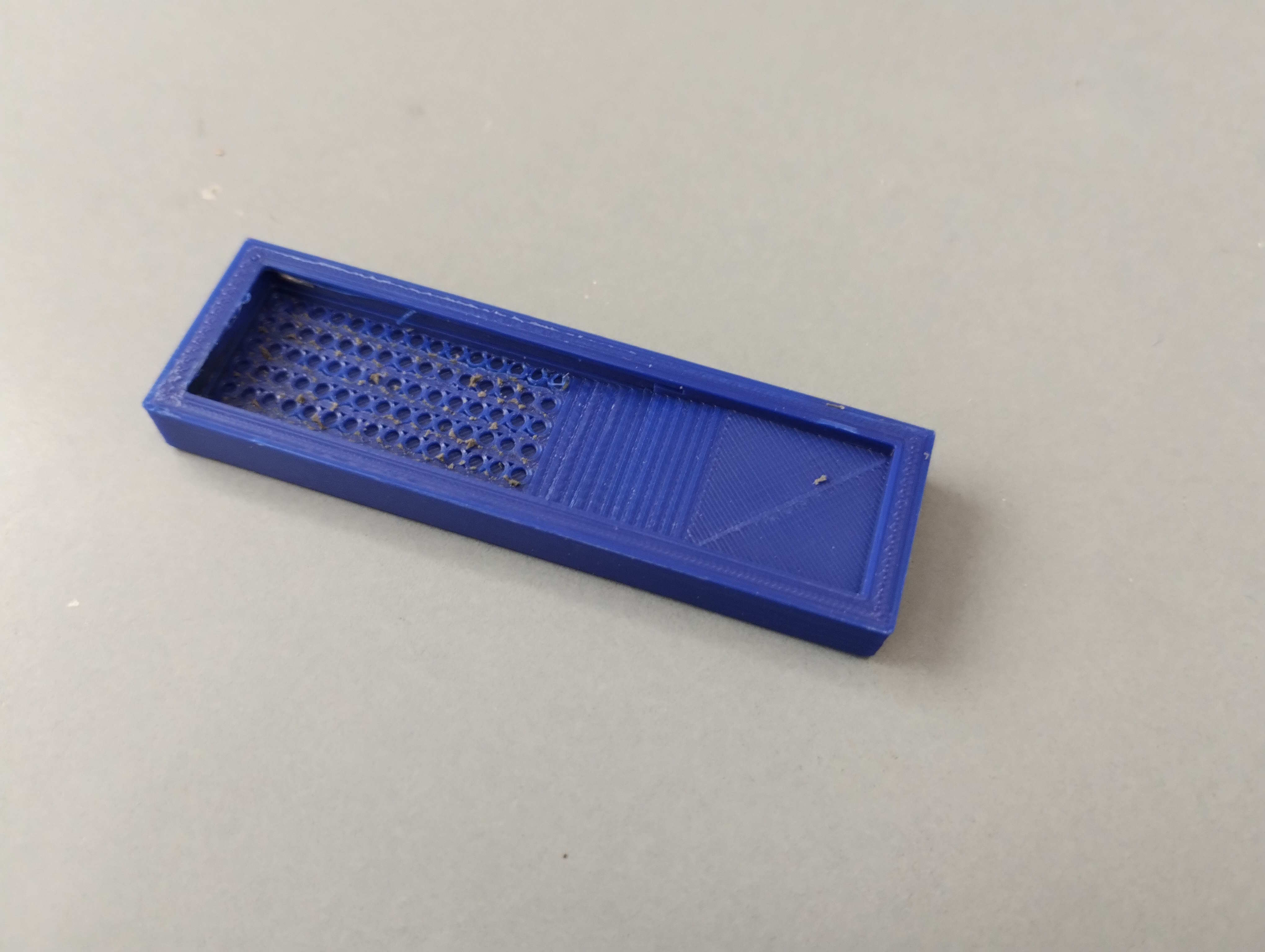
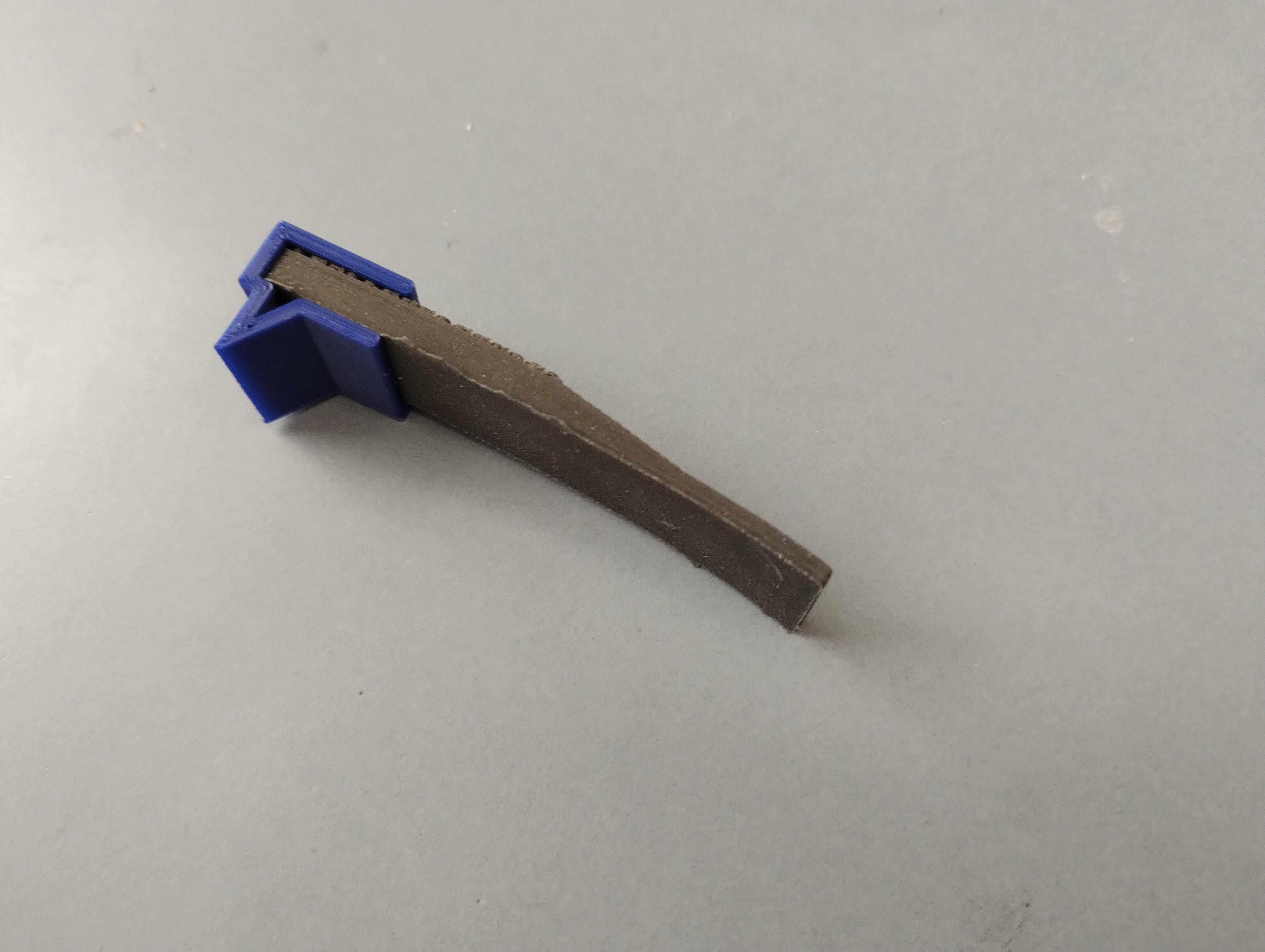
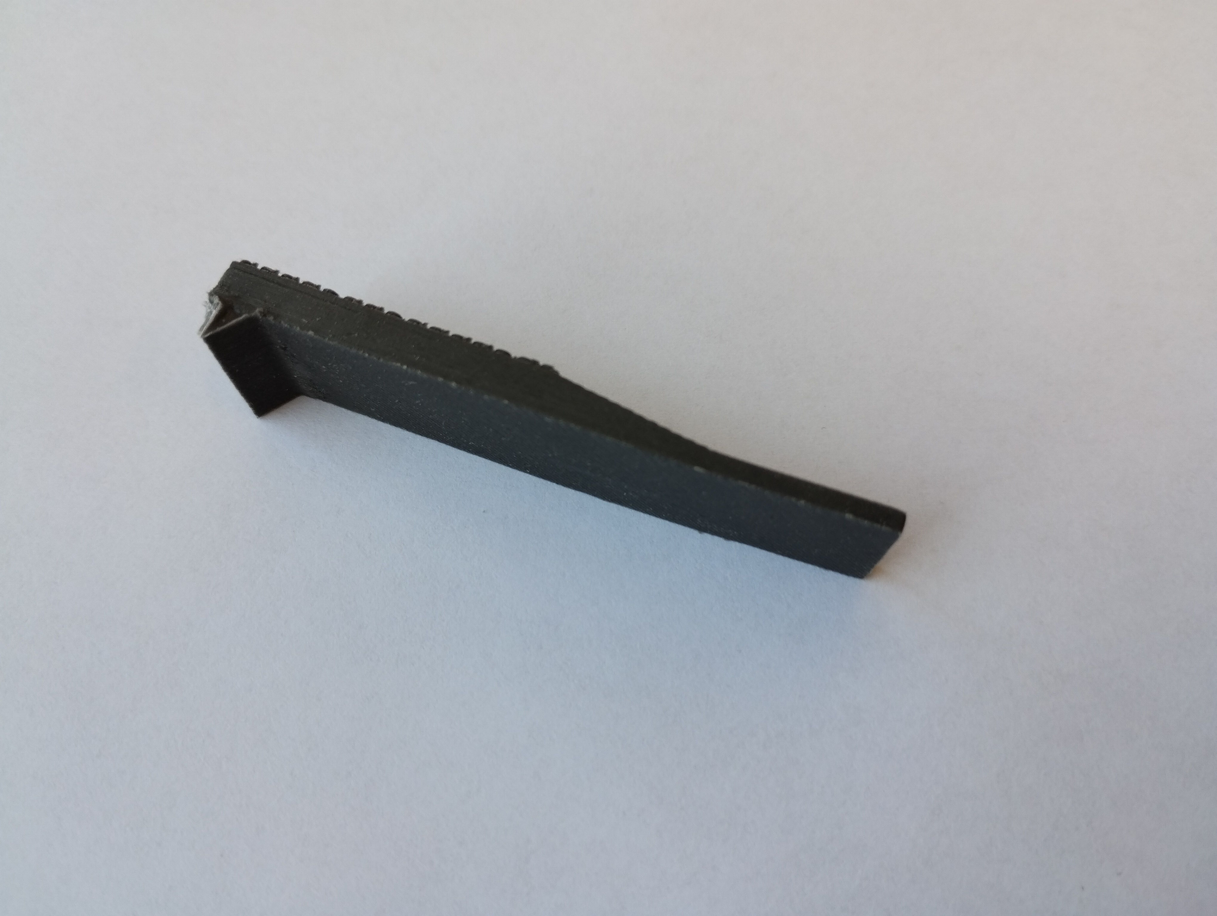
The MRE material was prepared according to the procedure described in Bernat et al. (2022). Three silicons with different properties were used to prepare MRE. These were Mold Star 15 (MS15) and Dragon Skin 10 (DS10) (both from Smooth-On) and RTV (OTT-S825 from OTTSilicone). The iron powder with an average particle size of was weighed in a glass container and thoroughly mixed with each silicone until a homogeneous mixture was obtained. The weight ratio of silicone to iron powder was equal to 1:1. Then, in the case of RTV silicone, the catalyst was added in an amount of 2% by weight relative to the amount of silicone. The MS15 and DS10 are two-component silicons in which one of the components already contains a catalyst. After thorough mixing, the resulting mixture was degassed by vacuum treatment. Finally, the mixture was poured into the mold presented in Fig. 7a. After 24 h, the MRE material was removed from the mold and carefully checked for bubbles in the structure. In the next step, the mixture of silicone with iron was prepared with the same procedure as before and the second part of the gripper was prepared (Fig. 7b). Both parts of the mold were made by 3D printing. The final gripper finger is presented in Fig. 7c.
2.4 Mechanical properties of silicons and MREs
The mechanical properties, i.e. tensile tests, of individual silicones and MREs made on their basis were examined to connect the properties of the obtained MREs with their action as actuators. Pure silicone samples (DS10, MS15, RTV) and MREs obtained from them were prepared as bars with dimensions of 50 mm length, 15 mm width, and 2 mm thickness. The tests were carried out at a traverse speed of 5 mm/min up to 30% of sample strain for Young’s modulus () determination, and 50 mm/min for the remaining part of the test in order to determine the stress value at 100% () and 300% () sample strain. The initial force was .
3 The Experiments
This section describes a series of experiments to verify the proposed concept. Firstly, the production of the gripper is discussed and then its validation is described.
3.1 Gripper Construction
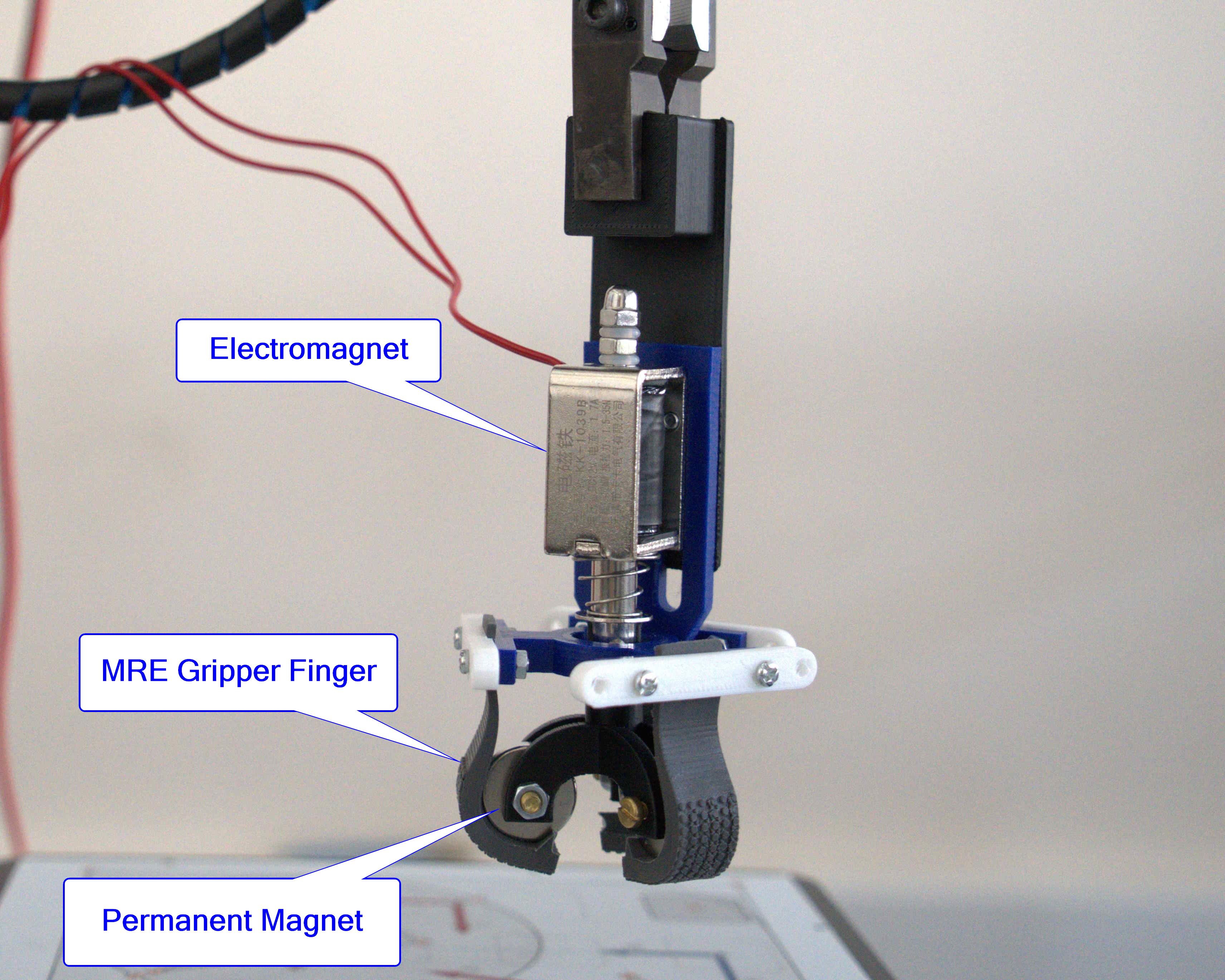
The gripper is constructed of three MRE stripes, three permanent magnets, a linear electromagnet, and a frame created by additive manufacturing. The parameters of the MRE finger, linear electromagnet, frame, and permanent magnet are provided in Table 1. Relying on them and the open/closed radius presented in Fig. 6 is equal to and . Movement of the frame with permanent magnets is ensured by a linear electromagnet with a spring defined in Table 1. In our gripper, the input signal is the voltage applied to the electromagnet. The turn on the gripper causes its opening and the turn off causes its closing. The concept of the gripper is presented in Fig. 8b, where the most important elements such as electromagnet (the element that allows controlling gripping process), permanent magnets (which allow rolling around them) and MREs (a crucial part of the gripper that allows gripping objects using its magnetic abilities and makes the gripper soft) are marked.
| Name (Symbol) | Value | Unit |
|---|---|---|
| MRE finger width () | 15 | |
| MRE finger length | 60 | |
| MRE finger thickness | 2-4 | |
| Mounting frame radius () | 18 | |
| EM move range | 12 | |
| EM rated current | 0.7 | |
| EM rated voltage | 12 | |
| EM max load | 3.5 | |
| PM inner diameter | 4.2 | |
| PM outer diameter () | 20 | |
| PM thickness | 5 | |
| PM remanence () | 1.21-1.25 | |
| PM coercivity () | 899 |
3.2 Validation
The aim of the validation process was to verify the basic principle of the gripper operation, its holding possibility of various objects, repeatedly holding process and measure the gripper finger pushing force.
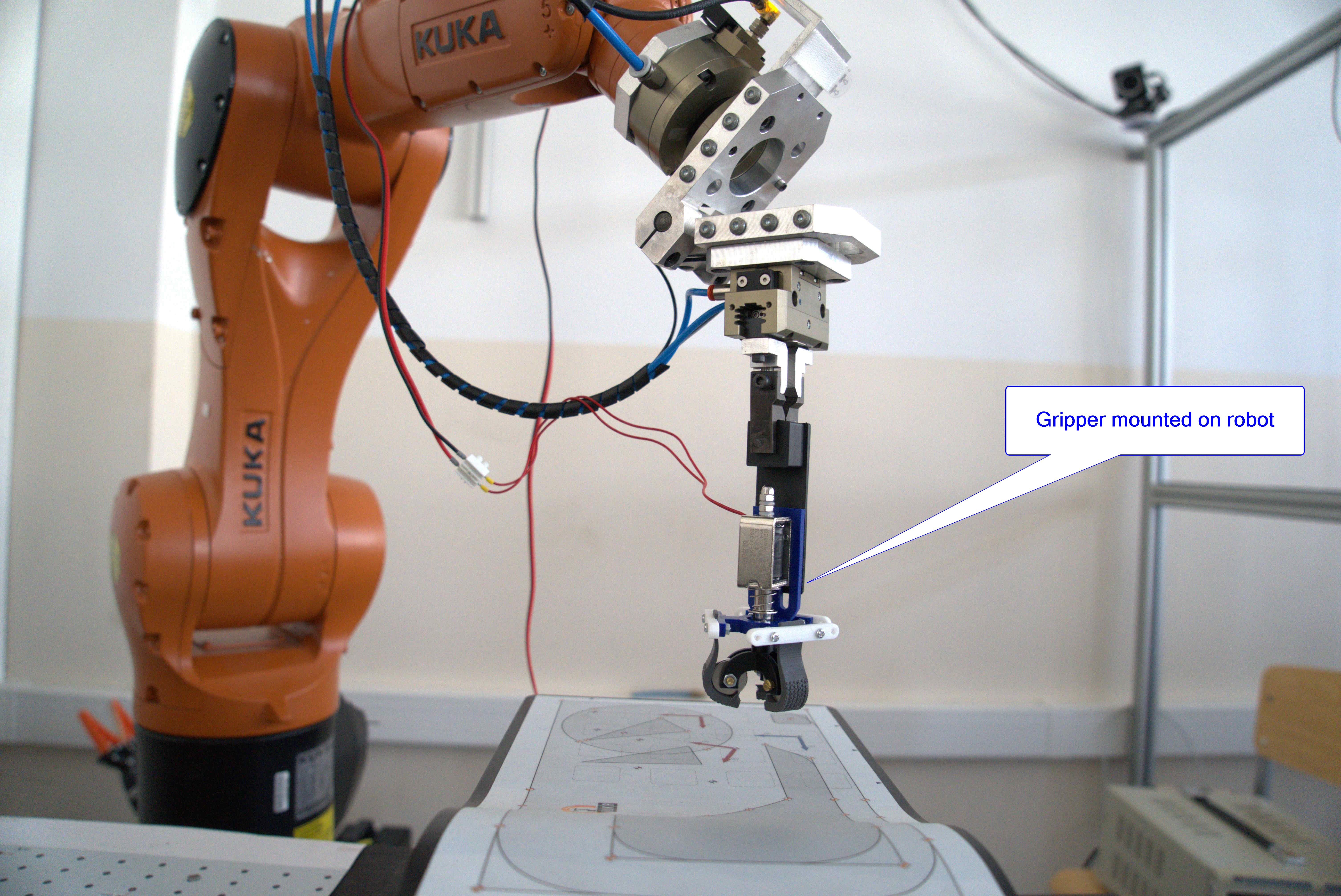
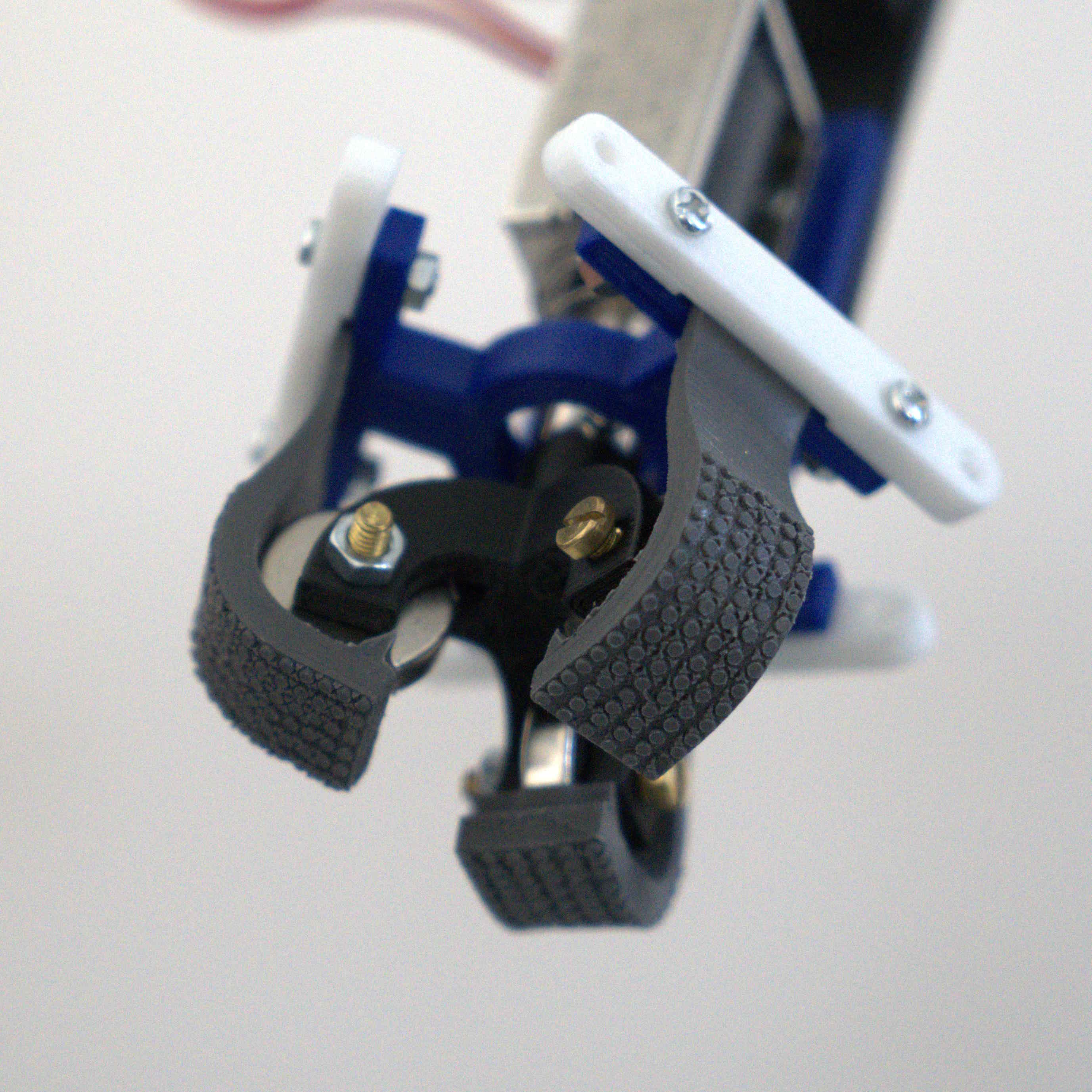
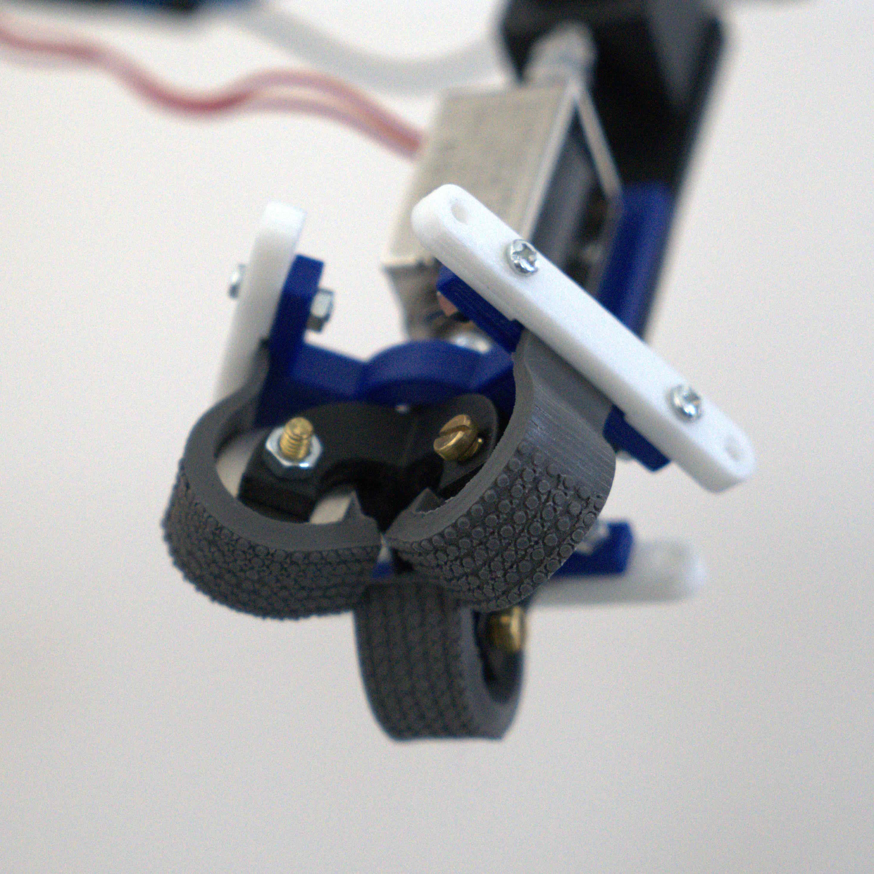
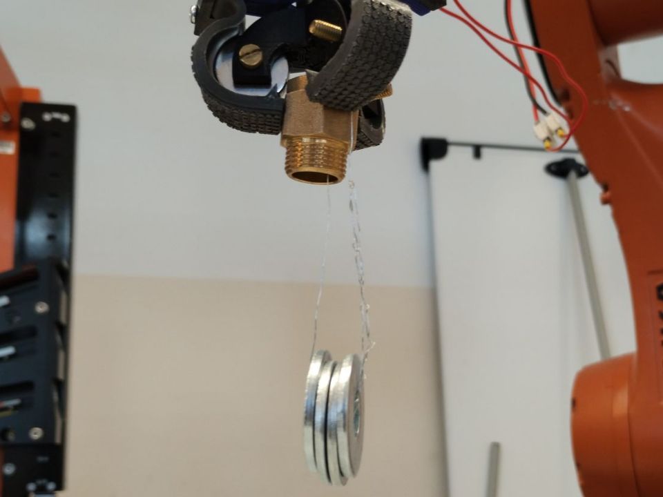
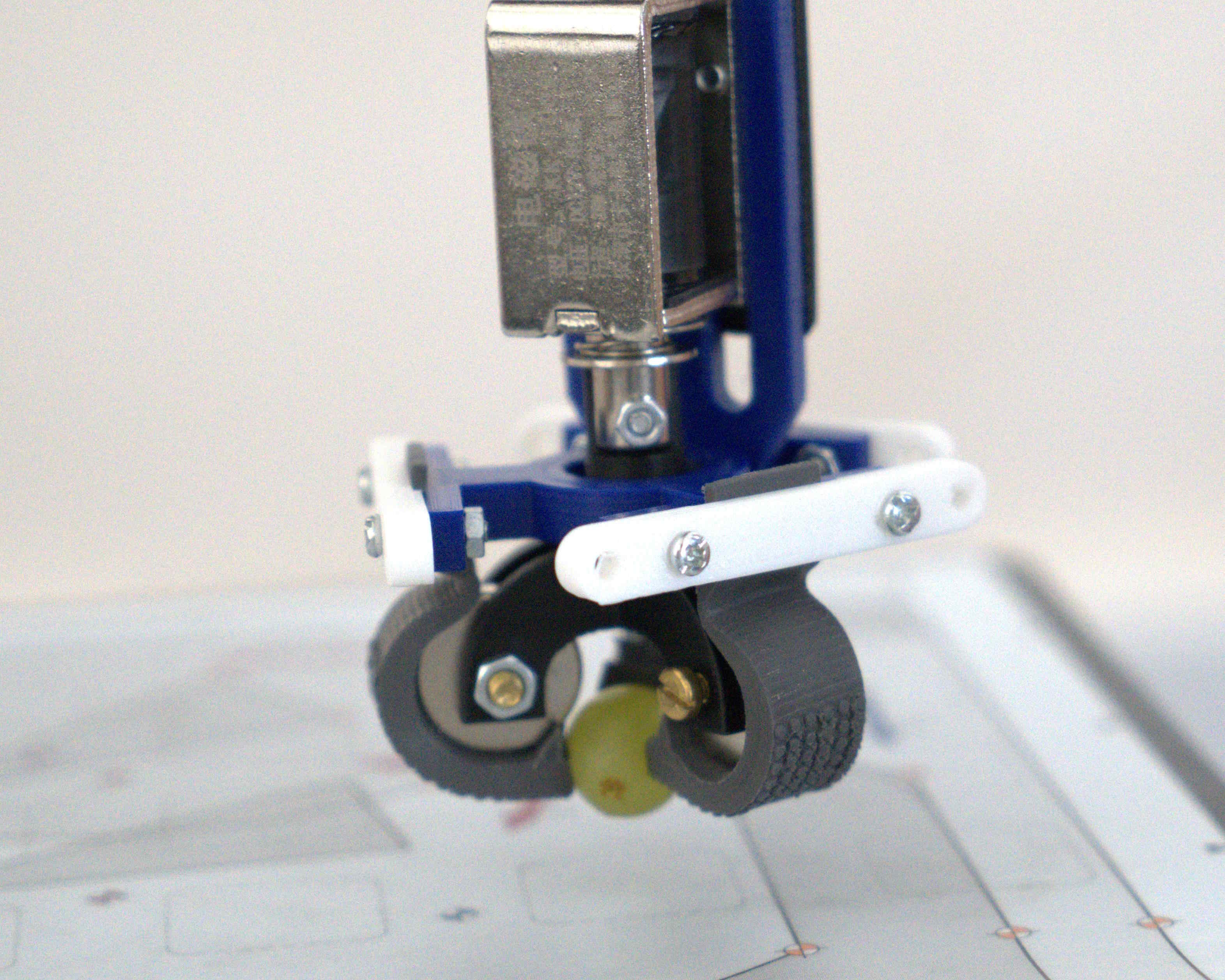
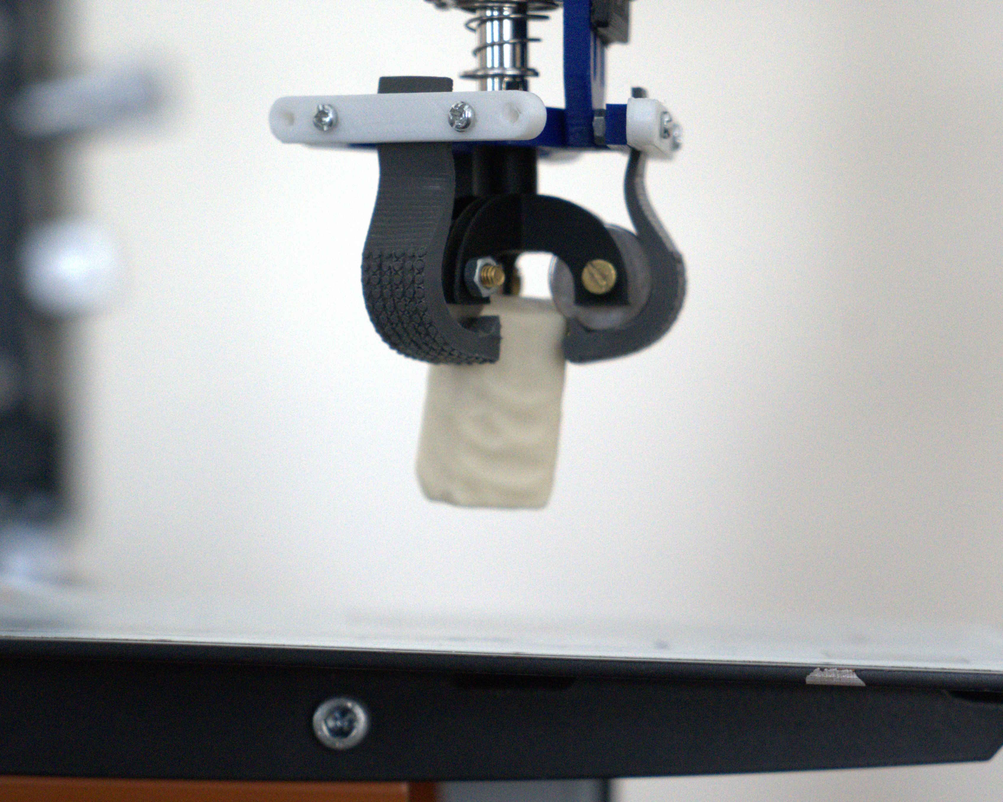
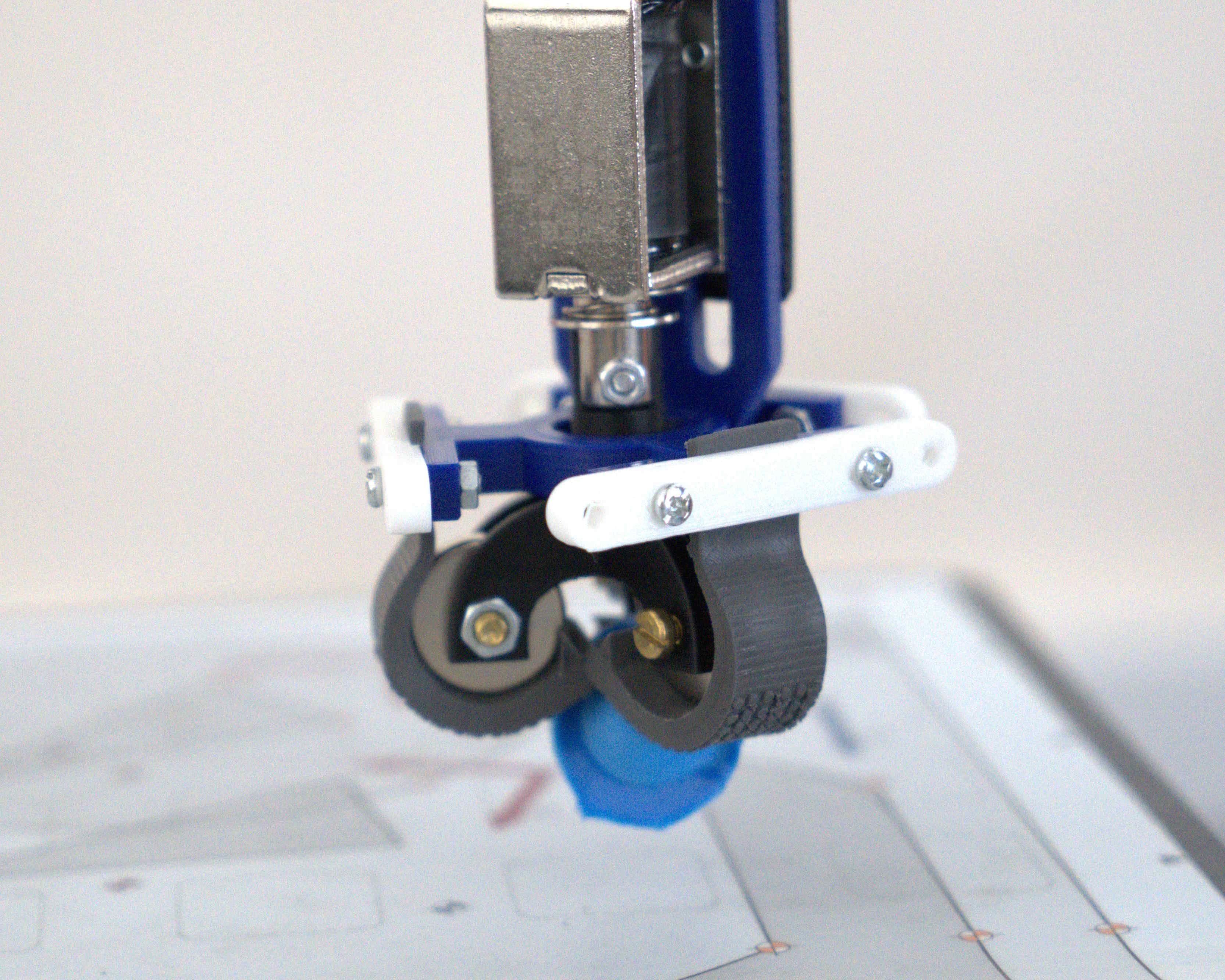
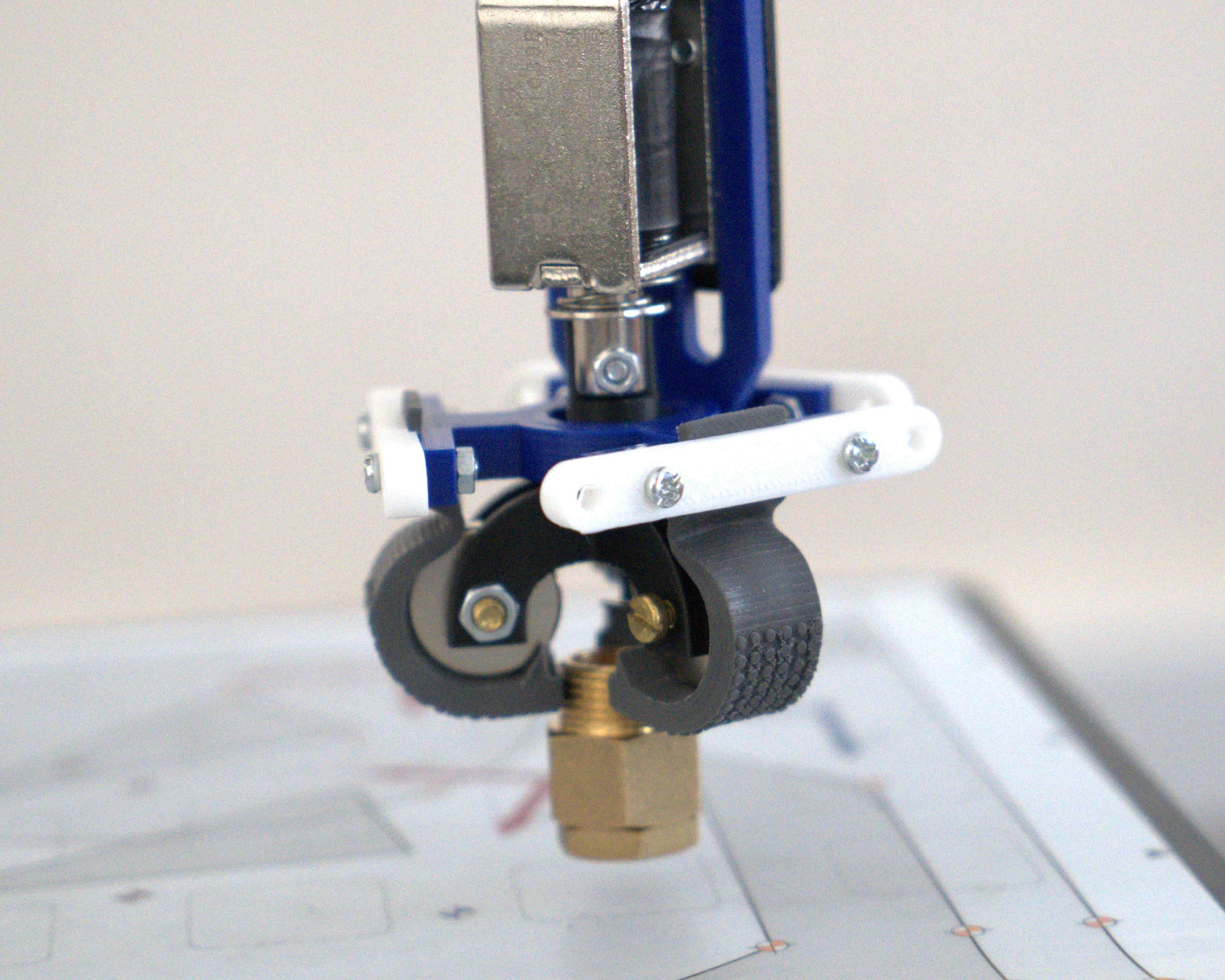
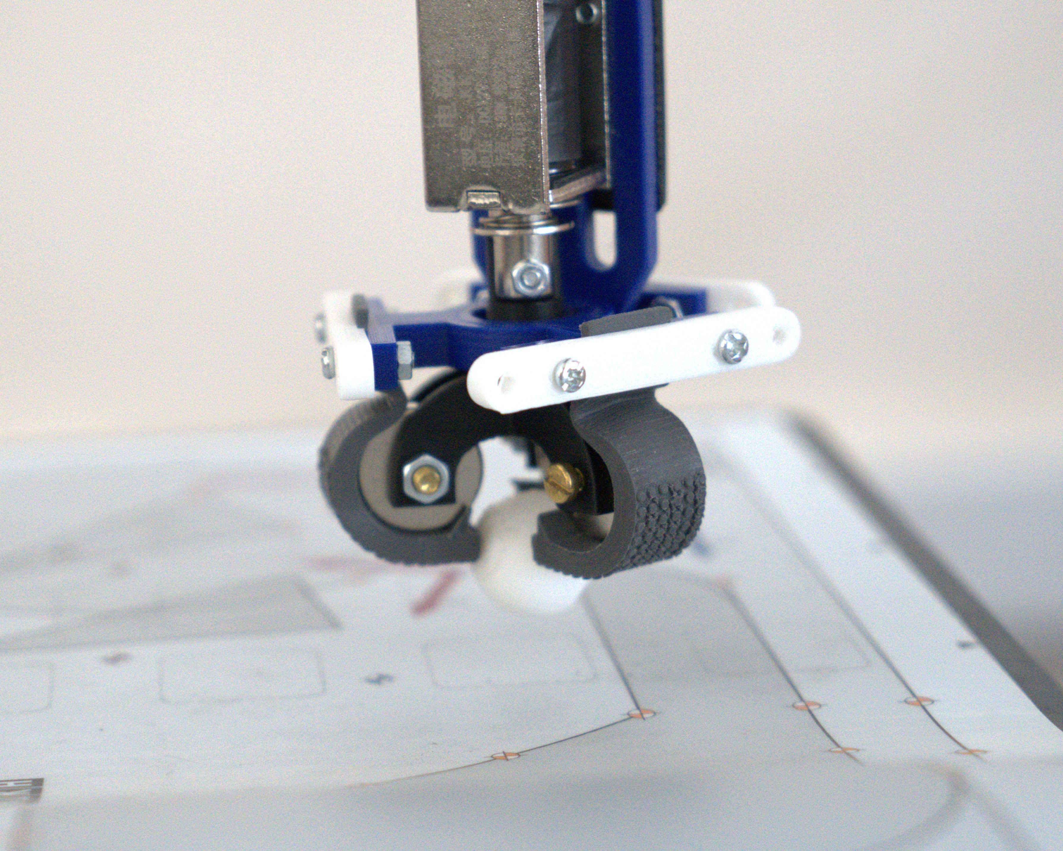
The validation of the gripper was conducted by a series of experiments with the gripper mounted on the KUKA manipulator (KR 6 R900). Fig. 9a and 9b show two states of this device: a) this is the first situation when the gripper is open, whereas b) shows what happens when the gripper is closed and the rolling effect around the permanent magnets is visible. In Fig. 9b it can be seen that the rolling around of the MRE stripes causes them to come closer to each other and at this point, the grip occurs. According to Fig. 6 the radius can be slightly lower due to the possibility of compressing MRE finger corners when touching.
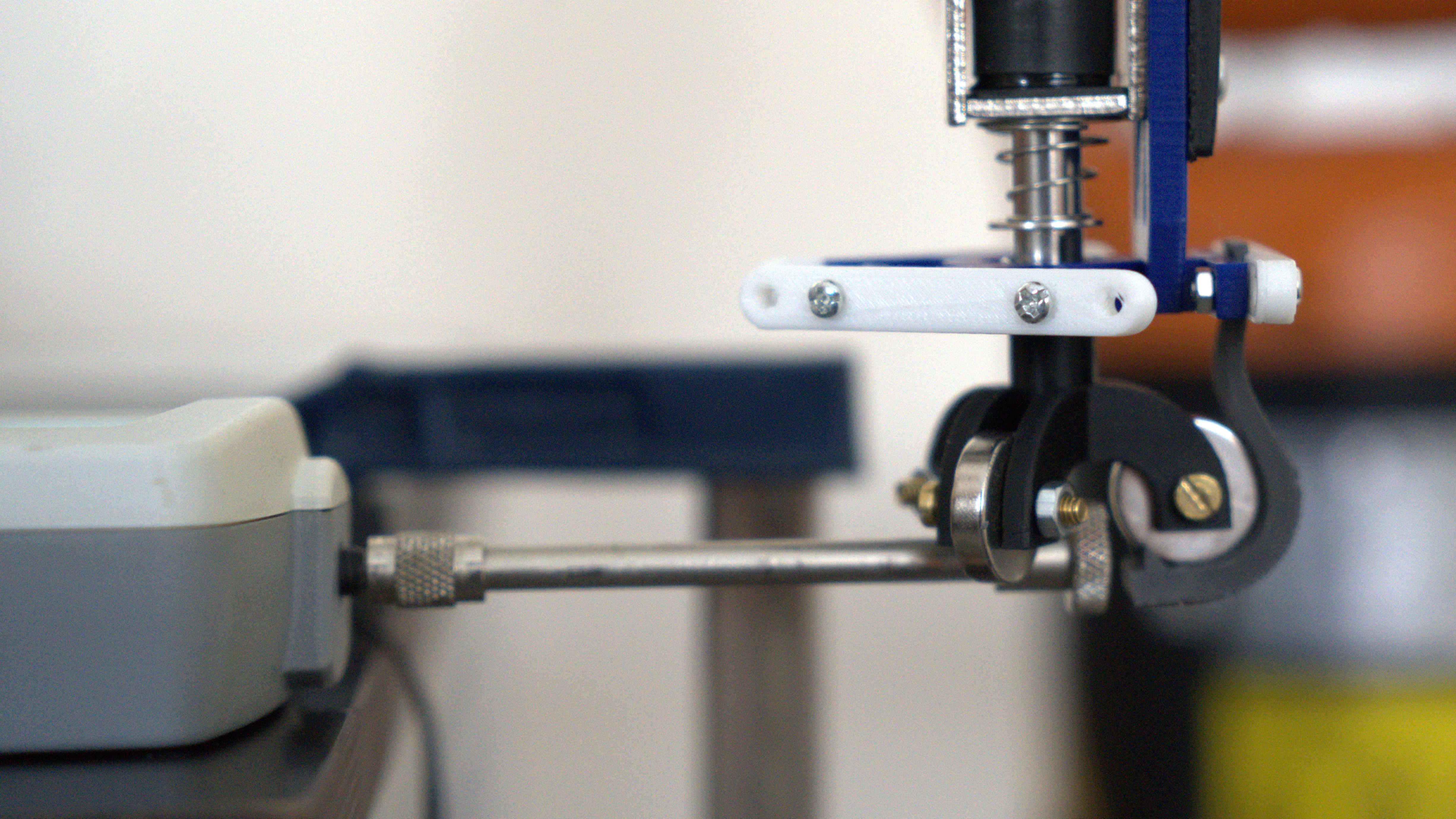
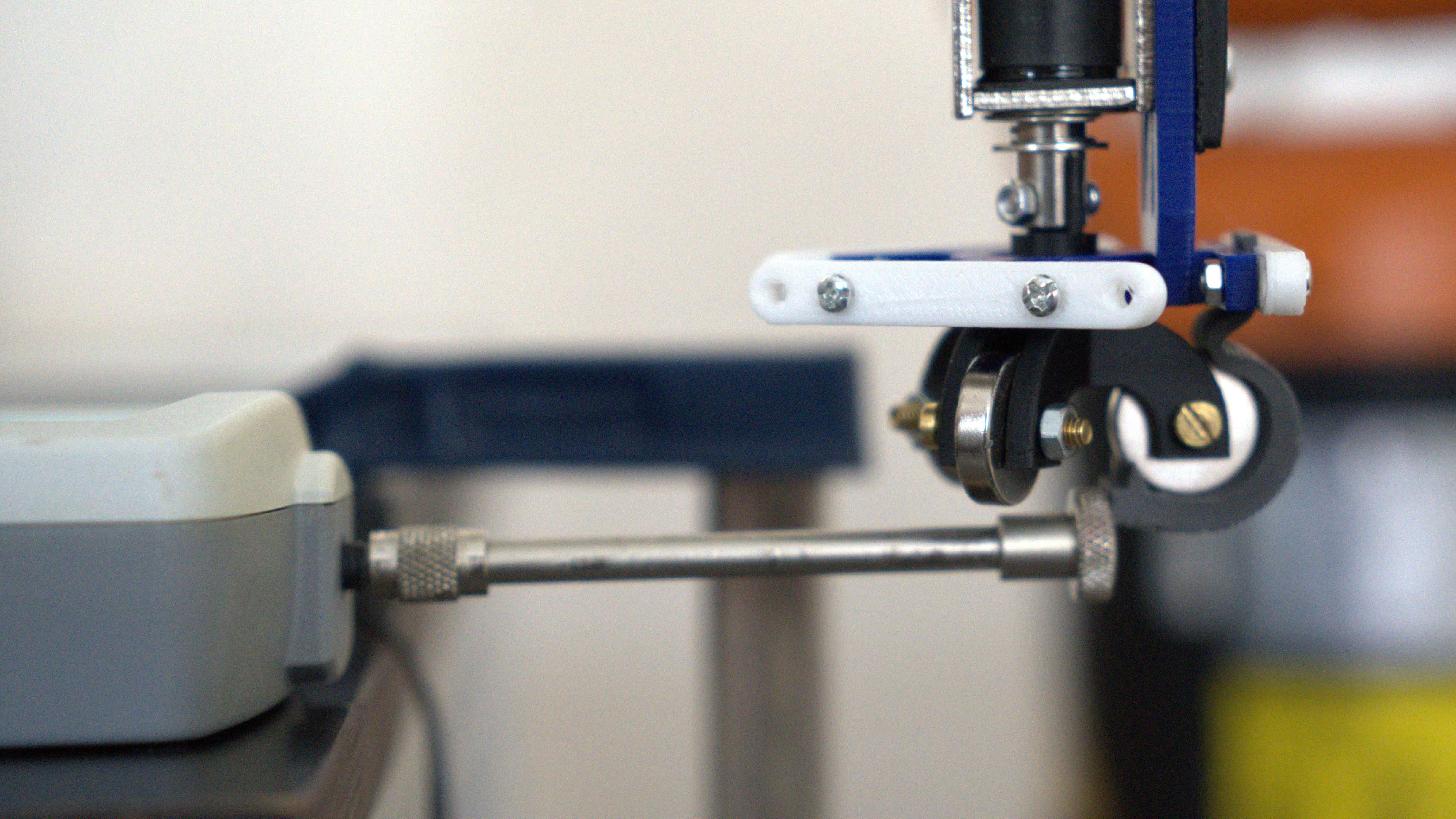
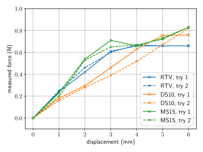
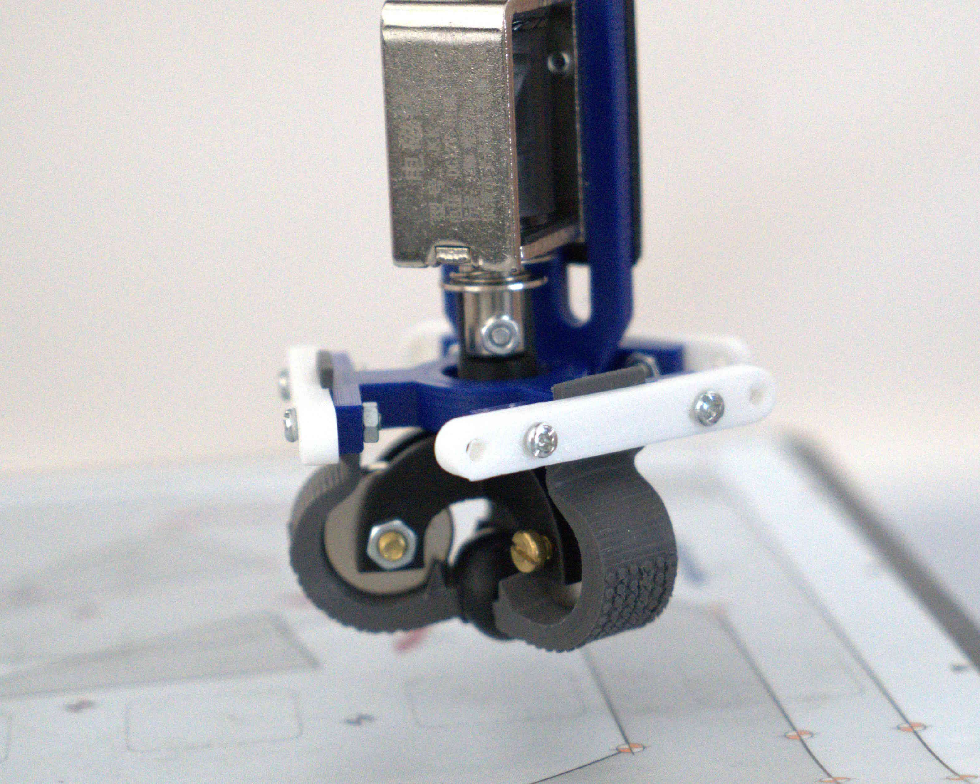
An additional experiment was conducted on the single gripper finger to get to know the force acting in the closed state. The gripper with removed two fingers was set up with the force sensor (Axis FB20) as presented in Fig. 10. The gripper was turned on/off five times. Each time, in the closed gripper state the force was read from the sensors. The average force is and it shows that gripper fingers produce force when they are rotated on permanent magnets. In the next experiment, the finger was in the closed state, and the force sensor was set up almost touching. Then, the robot was moved with step touching the force sensor. The resulting characteristics are visible in Fig. 11. It is visible that all materials have almost the same characteristics.
The experiment showing the operation of the gripper, its maximum range of grasp, and lifting capacity were carried out on 6 different objects. Tab. 2 presents the specification of lifting elements (in the case of irregular shape, diameter describes the outer outline). All elements were successfully gripped 10 times for 10 tries (only the bilberry has an 8/10 ratio). The overall success rate of gripping is equal to . The maximum mass of the lifted object was (brass element). The speed of closing or opening of the gripper was estimated based on the movie. The closing time is about and opening time is about .
| Name (Figure) | Mass | Dimension |
|---|---|---|
| Grape (13a) | 2.50g | H=18, D=15mm |
| Bilberry (13b) | 2.00g | H=13mm, D=16.5mm |
| Candy (13c) | 16.34g | H=40mm, W=25mm, L=17mm |
| Silicon hat (13d) | 2.75g | W=25mm, H=28 mm |
| Brass element (13e) | 28.00g | H=25mm, D=22mm |
| White ball (13f) | 2.07g | D=20mm |
What is very important all photos in Fig. 13 were taken in the same camera position and gravity acts vertically downwards. As presented, the orientation of the gripper does not affect gripping ability (so it is independent of gravity). The properties of MRE, its rough surface, and the strong magnetic force result in a firm gripping effect, which means that all types of elements used for validation did not slip out.
Finally, the test of all materials was performed to find the maximum mass that the gripper could hold. The tests were performed with brass elements with attached additional metal washers as it is visible in Fig. 12. Table 3 shows that the MRE prepared with RTV silicone can lift the largest mass, while the MRE prepared with DS15 silicone can lift the smallest mass, which is 2.4 times smaller than in the case of MRE with RTV silicone. The obtained results can be related to the mechanical properties, more precisely the tensile strength, of the obtained MREs. With the increase of stiffness (higher values) and strength of materials (higher values of and ), the maximum mass that can be lifted by the gripper made of MREs increases.
| Name | , | , | , | Maximum Mass, |
|---|---|---|---|---|
| pure RTV | 0.52 | 0.87 | - | - |
| pure MS10 | 0.45 | 0.72 | 4.54 | - |
| pure DS15 | 0.22 | 0.28 | 2.13 | - |
| MRE with RTV | 0.81 | 1.64 | - | 97.4 |
| MRE with MS10 | 0.78 | 0.93 | 4.04 | 86.5 |
| MRE with DS15 | 0.36 | 0.48 | 2.24 | 40.2 |
3.3 Discussion
In the presented gripper the object grasping is based on the interaction between permanent magnet and magnetorheological elastomer stripe. The combination of rolling magnetorheological elastomer on the permanent magnet for creating the gripper is a novel concept from the point of view of author knowledge in literatures Zhang et al. (2021); Skfivan et al. (2019); Choi et al. (2020); Bernat et al. (2022); Guan et al. (2022); Böse et al. (2021); Cramer et al. (2018).
In general, the comparison of soft grippers quantitative indicators like lifting mass is difficult due to its variety of geometry and size - all grippers presented in works Zhang et al. (2021); Skfivan et al. (2019); Choi et al. (2020); Bernat et al. (2022); Guan et al. (2022); Choi et al. (2018, 2023) have different properties. In most cases, the same gripper design can be scaled to be larger or to be smaller to obtain different indicators.
In this work, the presented construction can create a normally open or closed state and hence it does not require power to hold objects or to be opened. Furthermore, from the author’s point of view, the gripper is easy to produce with commonly accessible materials. The gripper is controlled by voltage excitation which is easily accessible and has fast response time. It has a much bigger maximum load capability (up to 10 times greater) in comparison to the finger based grippers defined in work Bernat et al. (2022); Guan et al. (2022). Alternatively, the soft gripper based on the suction cup Zhang et al. (2021) has a lifting ability of about with a current of about , but this kind of gripper cannot manipulate objects (has no fingers). In our case, we energised the electromagnet and , which makes our gripper more energy efficient.
Furthermore, in our solution, the behaviour of the gripper fingers does not depend on the direction of gravity. Relying on the experiments, it was visible that the gripper process is very stable. This means that the gripper catches the object on the first try in most of the experiments. Furthermore, the speed of the gripper is very fast in comparison to work Skfivan et al. (2019) (up to 4 times).
In further work, it is possible to independently control each gripper finger. This gives the ability to manipulate objects in a more sophisticated way than just grabbing. Furthermore, the authors believe that maximisation of the gripping force by providing anisotropy to MRE material with shape optimisation is possible because the study on the anisotropy in MRE materials shown improvement as summarised in work Böse et al. (2021).
4 Conclusion
In summary, the presented work introduces magnetorheological elastomer rolling on the permanent magnet, which is a novel mechanism in contrast to previous soft magnetic robots presented in the literature. The proposed mechanism is applied to construct a novel soft gripper. The main advantages of the proposed soft gripper are as follows. It is simply to build with readily available materials. As shown in the experiments, it can hold a variety of items, such as 3D-printed elements, a ball, a silicon cap, or brass elements. The overall success rate of gripping is almost . The gripper can hold an element weighing up to about 97 grams, which is enough to lift small everyday usage objects like fruits or candies. Furthermore, the usage of soft fingers enables one to apply to grasping delicate objects.
Acknowledge
This research was funded by the Ministry of Education and Science, grant number 0211/SBAD/0123. The authors would like to thank dr Paweł Szulczyński for help in conducting of experiments with a KUKA robot.
References
- Rateni et al. [2015] Giovanni Rateni, Matteo Cianchetti, Gastone Ciuti, Arianna Menciassi, and Cecilia Laschi. Design and development of a soft robotic gripper for manipulation in minimally invasive surgery: a proof of concept. Meccanica, 50:2855–2863, 2015. doi:10.1007/s11012-015-0261-6.
- Erb et al. [2016] Randall M. Erb, Joshua J. Martin, Rasam Soheilian, Chunzhou Pan, and Jabulani R. Barber. Actuating soft matter with magnetic torque. Advanced Functional Materials, 26(22):3859–3880, 2016. doi:10.1002/adfm.201504699.
- Ren et al. [2019] Ziyu Ren, Tianlu Wang, Wenqi Hu, and Metin Sitti. A magnetically-actuated untethered jellyfish-inspired soft milliswimmer. In Proceedings of Robotics: Science and Systems, FreiburgimBreisgau, Germany, June 2019. doi:10.15607/RSS.2019.XV.013.
- Eshaghi et al. [2021] Mehdi Eshaghi, Mohsen Ghasemi, and Korosh Khorshidi. Design, manufacturing and applications of small-scale magnetic soft robots. Extreme Mechanics Letters, 44:101268, 2021. ISSN 2352-4316. doi:10.1016/j.eml.2021.101268.
- Li et al. [2014] Yancheng Li, Jianchun Li, Weihua Li, and Haiping Du. A state-of-the-art review on magnetorheological elastomer devices. Smart materials and structures, 23(12):123001, 2014. doi:10.1088/0964-1726/23/12/123001.
- Lin et al. [2023] Dezhao Lin, Fan Yang, Di Gong, and Ruihong Li. A new vibration isolator integrating tunable stiffness-damping and active driving properties based on radial-chains magnetorheological elastomer. Mechanical Systems and Signal Processing, 183:109633, 2023. ISSN 0888-3270. doi:10.1016/j.ymssp.2022.109633.
- Bira et al. [2020] Nicholas Bira, Pallavi Dhagat, and Joseph R Davidson. A review of magnetic elastomers and their role in soft robotics. Frontiers in Robotics and AI, 7:588391, 2020. doi:10.3389/frobt.2020.588391.
- Böse et al. [2021] Holger Böse, Thomas Gerlach, and Johannes Ehrlich. Magnetorheological elastomers—an underestimated class of soft actuator materials. Journal of Intelligent Material Systems and Structures, 32(14):1550–1564, 2021. doi:10.1177/1045389X21990888.
- Mahoney and Abbott [2014] Arthur W. Mahoney and Jake J. Abbott. 5-dof manipulation of an untethered magnetic device in fluid using a single permanent magnet. In Proceedings of Robotics: Science and Systems, 2014. doi:10.15607/RSS.2014.X.037.
- Popek et al. [2017] Katie M. Popek, Tucker Hermans, and Jake J. Abbott. First demonstration of simultaneous localization and propulsion of a magnetic capsule in a lumen using a single rotating magnet. In 2017 IEEE International Conference on Robotics and Automation (ICRA), pages 1154–1160, 2017. doi:10.1109/ICRA.2017.7989138.
- Culha et al. [2020] Utku Culha, Sinan O. Demir, Sebastian Trimpe, and Metin Sitti. Learning of sub-optimal gait controllers for magnetic walking soft millirobots. In Proceedings of Robotics: Science and Systems, 2020. doi:10.15607/RSS.2020.XVI.070.
- Bernat et al. [2022] Jakub Bernat, Piotr Gajewski, Rafał Kapela, Agnieszka Marcinkowska, and Paulina Superczyńska. Design, fabrication and analysis of magnetorheological soft gripper. Sensors, 22(7), 2022. ISSN 1424-8220. doi:10.3390/s22072757.
- Cramer et al. [2018] Jeroen Cramer, Martijn Cramer, Eric Demeester, and Karel Kellens. Exploring the potential of magnetorheology in robotic grippers. In Procedia CIRP, volume 76, page 127 – 132, 2018. doi:10.1016/j.procir.2018.01.038.
- Rus and Tolley [2015] Daniela Rus and Michael T. Tolley. Design, fabrication and control of soft robots. Nature, 521(7553):467–475, May 2015. ISSN 1476-4687. doi:10.1038/nature14543.
- Navas et al. [2021] Eduardo Navas, Roemi Fernandez, Delia Sepúlveda, Manuel Armada, and Pablo Gonzalez-de Santos. Soft grippers for automatic crop harvesting: A review. Sensors, 21(8):2689, 2021. doi:10.3390/s21082689.
- Shintake et al. [2018] Jun Shintake, Vito Cacucciolo, Dario Floreano, and Herbert Shea. Soft robotic grippers. Advanced materials, 30(29):1707035, 2018. doi:10.1002/adma.201707035.
- Pagoli et al. [2021] Amir Pagoli, Frédéric Chapelle, Juan-Antonio Corrales-Ramon, Youcef Mezouar, and Yuri Lapusta. Review of soft fluidic actuators: classification and materials modeling analysis. Smart Materials and Structures, 31(1):013001, dec 2021. doi:10.1088/1361-665X/ac383a.
- Pettersson et al. [2010] Anders Pettersson, Steve Davis, John O Gray, Tony J Dodd, and Tomas Ohlsson. Design of a magnetorheological robot gripper for handling of delicate food products with varying shapes. Journal of Food Engineering, 98(3):332–338, 2010. doi:10.1016/j.jfoodeng.2009.11.020.
- Dinakaran et al. [2023] Venkatesa Prabu Dinakaran, Meenakshi Priya Balasubramaniyan, Suresh Muthusamy, and Hitesh Panchal. Performa of scara based intelligent 3 axis robotic soft gripper for enhanced material handling. Advances in Engineering Software, 176:103366, 2023. ISSN 0965-9978. doi:10.1016/j.advengsoft.2022.103366.
- Mosadegh et al. [2014] Bobak Mosadegh, Panagiotis Polygerinos, Christoph Keplinger, Sophia Wennstedt, Robert F Shepherd, Unmukt Gupta, Jongmin Shim, Katia Bertoldi, Conor J Walsh, and George M Whitesides. Pneumatic networks for soft robotics that actuate rapidly. Advanced functional materials, 24(15):2163–2170, 2014. doi:10.1002/adfm.201303288.
- Washio et al. [2022] Shogo Washio, Kieran Gilday, and Fumiya Iida. Design and control of a multi-modal soft gripper inspired by elephant fingers. In 2022 IEEE/RSJ International Conference on Intelligent Robots and Systems (IROS), pages 4228–4235, 2022. doi:10.1109/IROS47612.2022.9982126.
- Araromi et al. [2015] Oluwaseun A. Araromi, Irina Gavrilovich, Jun Shintake, Samuel Rosset, Muriel Richard, Volker Gass, and Herbert R. Shea. Rollable multisegment dielectric elastomer minimum energy structures for a deployable microsatellite gripper. IEEE/ASME Transactions on Mechatronics, 20(1):438–446, 2015. doi:10.1109/TMECH.2014.2329367.
- Shintake et al. [2015] Jun Shintake, Bryan Schubert, Samuel Rosset, Herbert Shea, and Dario Floreano. Variable stiffness actuator for soft robotics using dielectric elastomer and low-melting-point alloy. In 2015 IEEE/RSJ International Conference on Intelligent Robots and Systems (IROS), pages 1097–1102, 2015. doi:10.1109/IROS.2015.7353507.
- Zhang et al. [2021] Peizhi Zhang, Mitsuhiro Kamezaki, Zhuoyi He, Hiroyuki Sakamoto, and Shigeki Sugano. Epm–mre: Electropermanent magnet–magnetorheological elastomer for soft actuation system and its application to robotic grasping. IEEE Robotics and Automation Letters, 6(4):8181 – 8188, 2021. doi:10.1109/LRA.2021.3100939.
- Skfivan et al. [2019] Vojtěch Skfivan, Ondřej Sodomka, and František Mach. Magnetically guided soft robotic grippers. In 2019 2nd IEEE International Conference on Soft Robotics (RoboSoft), pages 126–130, 2019. doi:10.1109/ROBOSOFT.2019.8722762.
- Choi et al. [2020] Dong-Soo Choi, Tae-Hoon Kim, Seok-Han Lee, Changhyun Pang, Jin Woo Bae, and Sang-Youn Kim. Beyond human hand: Shape-adaptive and reversible magnetorheological elastomer-based robot gripper skin. ACS Applied Materials and Interfaces, 12(39):44147 – 44155, 2020. doi:10.1021/acsami.0c11783.
- Guan et al. [2022] Ruihua Guan, Hengyu Zheng, Qingxiao Liu, KangTai Ou, Dian-sen Li, Jiang Fan, Qiang Fu, and Youyi Sun. Diw 3d printing of hybrid magnetorheological materials for application in soft robotic grippers. Composites Science and Technology, 223, 2022. doi:10.1016/j.compscitech.2022.109409.
- Choi et al. [2018] Young T. Choi, Christine M. Hartzell, Thomas Leps, and Norman M. Wereley. Gripping characteristics of an electromagnetically activated magnetorheological fluid-based gripper. AIP Advances, 8(5), 2018. doi:10.1063/1.5006094.
- Choi et al. [2023] Young T. Choi, Christine M. Hartzell, and Norman M. Wereley. Holding performance of an adaptive magnetorheological fluid-based robotic claw. IEEE Transactions on Magnetics, 59(11), 2023. doi:10.1109/TMAG.2023.3299702.
- Yang et al. [2022] Jian Yang, Shuaishuai Sun, Xiaoyan Yang, Yufan Ma, Guolin Yun, Ruizhe Chang, Shi-Yang Tang, Masami Nakano, Zhixiong Li, Haiping Du, Shiwu Zhang, and Weihua Li. Equipping new sma artificial muscles with controllable mrf exoskeletons for robotic manipulators and grippers. IEEE/ASME Transactions on Mechatronics, 27(6):4585 – 4596, 2022. doi:10.1109/TMECH.2022.3157329.
- Ullrich et al. [2015] Franziska Ullrich, Kanika S Dheman, Simone Schuerle, and Bradley J Nelson. Magnetically actuated and guided milli-gripper for medical applications. In 2015 IEEE International Conference on Robotics and Automation (ICRA), pages 1751–1756. IEEE, 2015. doi:10.1109/ICRA.2015.7139424.
- Ding et al. [2023] Wenjie Ding, Yisong Zhou, Min Sun, Haonan Fu, Yiji Chen, Zheng Zhang, Zhi Pei, and Hao Chai. Magnetorheological elastomer actuated multi-stable gripper reinforced stiffness with twisted and coiled polymer. Thin-Walled Structures, 193, 2023. doi:10.1016/j.tws.2023.111223.
- Gao et al. [2022] Yinduan Gao, Huaxia Deng, Jingyi Zhang, Quan Shu, Zhenbang Xu, Xufeng Cao, Bochao Wang, and Xinglong Gong. Magnetic actuator with programmable force distribution and self-sensing for bidirectional deformation control. Advanced Materials Technologies, 7(10), 2022. doi:10.1002/admt.202200047.
- Ren and Razek [1992] Z. Ren and A. Razek. Local force computation in deformable bodies using edge elements. IEEE Transactions on Magnetics, 28(2):1212 – 1215, 1992. doi:10.1109/20.123904.
- Carpentier et al. [2014] Anthony Carpentier, Nicolas Galopin, Olivier Chadebec, and Grard Meunier. Modeling of magneto-mechanical coupling using magnetic volume integral and mechanical finite-element methods. IEEE Transactions on Magnetics, 50(2):233 – 236, 2014. doi:10.1109/TMAG.2013.2283600.